Levitronix PuraLev LCO-i100 User manual

User Manual for LCO-i100 Console
www.levitronix.com
PL-4066-00, Rev03, DCO# 21-230
First Release: 09-Feb-2017
Last Update: 07-Oct-2021
PuraLev®Console
LCO-i100
PuraLev®i30SU/MU, PuraLev®i100SU/MU
PuraLev®i600SU
USER MANUAL
This manual contains information necessary for the safe and proper use of the PuraLev®LCO-i100
Console. Included are specifications for the standard configurations and instructions regarding its use,
installation, operation, adjustment, inspection and maintenance. For detailed description of the menu
structure and the configuration possibilities with the touch screen user interface the console software
manual PL-4067-00 can be consulted. For all in this manual revision described configurations and features
the console software V1.04 R16 or higher is needed. For special configurations of the system refer to
accompanying information. Please familiarize yourself with the contents of the manual to ensure the safe
and effective use of this product. After reading this manual, please store the manual where the personnel
responsible for operating the pump system can readily refer to it at any time.

User Manual for LCO-i100 Console
www.levitronix.com
PL-4066-00, Rev03, DCO# 21-230
2
Table of Contents
1SAFETY PRECAUTIONS........................................................................................................................................................................3
2SPECIFICATIONS...................................................................................................................................................................................4
2.1 Specification of Console Components ..........................................................................................................................................4
2.2 System Overview and General Specification................................................................................................................................7
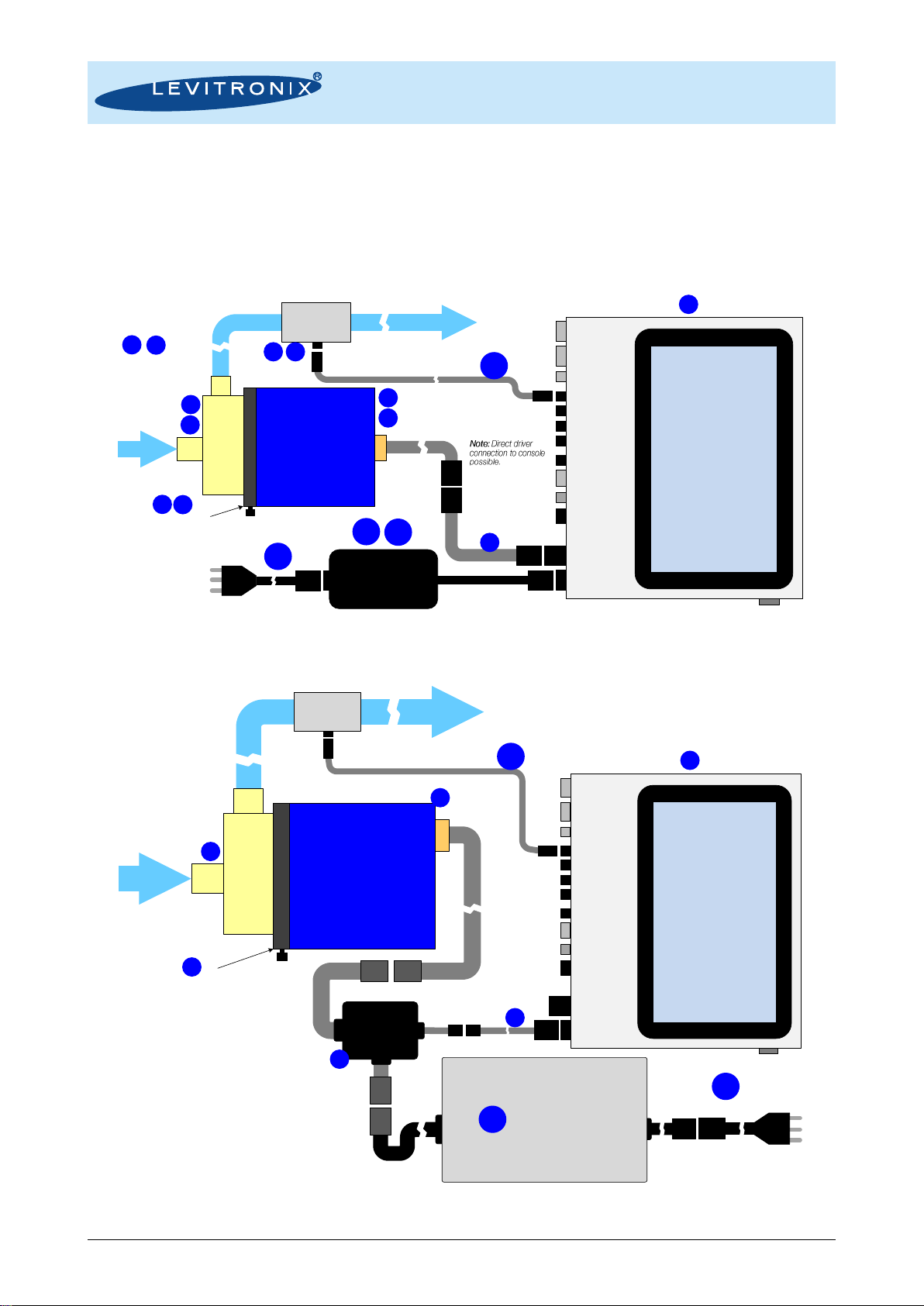
2.2.1 Basic Stand-Alone System Configuration..........................................................................................................................................................7
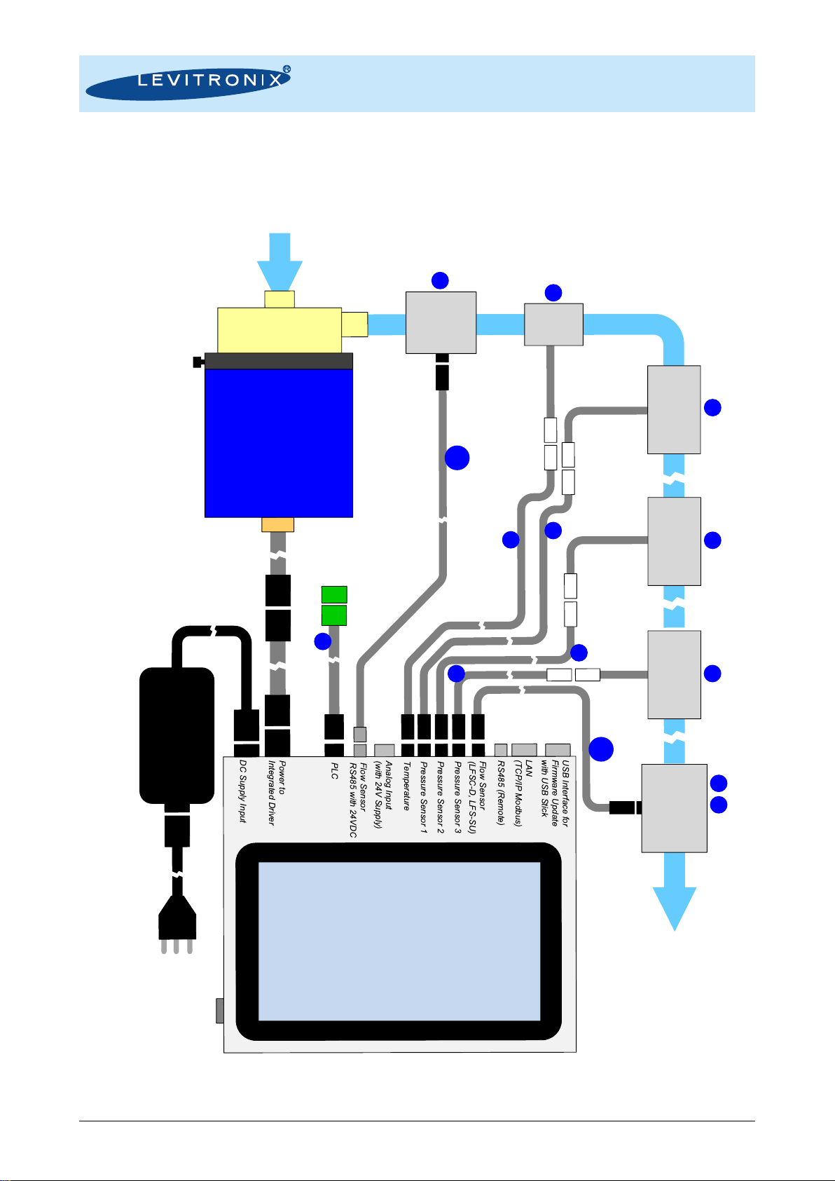
2.2.2 Extended System Configuration ........................................................................................................................................................................8
2.3 General Environmental Conditions................................................................................................................................................9
2.4 Basic Dimensions of Console........................................................................................................................................................9
3ENGINEERING INFORMATION ...........................................................................................................................................................10
3.1 IP Rating.......................................................................................................................................................................................10
3.2 Temperature Monitoring ..............................................................................................................................................................10
4INSTALLATION.....................................................................................................................................................................................10
4.1 Mechanical Installation.................................................................................................................................................................10
4.2 Electrical Installation ....................................................................................................................................................................11
4.2.1 Connection Overview.......................................................................................................................................................................................11
4.2.2 PLC Interface...................................................................................................................................................................................................12
4.2.3 Analog Input with 24VDC Supply.....................................................................................................................................................................13
4.2.4 General Installation Instructions ......................................................................................................................................................................14
5OPERATION..........................................................................................................................................................................................15
5.1 Basic System Operation ..............................................................................................................................................................15
5.1.1 Start-Up............................................................................................................................................................................................................15
5.1.2 Power-Down.....................................................................................................................................................................................................15
5.1.3 Auto-Resume Feature......................................................................................................................................................................................16
5.1.4 Software Update ..............................................................................................................................................................................................16
6MAINTENANCE.....................................................................................................................................................................................17
6.1 Cleaning .......................................................................................................................................................................................17
7TROUBLESHOOTING ..........................................................................................................................................................................17
8TECHNICAL SUPPORT........................................................................................................................................................................17
9APPENDIX .............................................................................................................................................................................................18
9.1 Regulatory Status.........................................................................................................................................................................18
9.1.1 CE Marking ......................................................................................................................................................................................................18
9.1.2 IECEE CB Safety Certification.........................................................................................................................................................................18
9.1.3 NRTL/ETL Safety Certification and Marking....................................................................................................................................................18
9.1.4 Disposal of Equipment –WEEE Directive 2012/19/EU...................................................................................................................................18
9.2 Symbols and Signal Words..........................................................................................................................................................19

User Manual for LCO-i100 Console
www.levitronix.com
PL-4066-00, Rev03, DCO# 21-230
3
1 Safety Precautions
The PuraLev®Console LCO-i100 is designed to be used in research laboratories and industrial production
environments in life science markets like biotech and pharmaceuticals. Installation shall be done by qualified
personnel only. Safety precautions and all “CAUTION”, “WARNING” and “DANGER” indications in the relevant
sections shall be followed.
Concerning safety precautions for motor, pump and sensors refer to the corresponding manuals.
CAUTION
Do not under any circumstances open the console enclosure. Levitronix®does
not assume responsibility for any damage, which occurs under such
circumstances.
!
WARNING
Hazardous voltage may be present.
Always isolate the console from the mains power supply before performing any
changes to the connections, the positioningand before doing other maintenance
activities.
Use the standard specified AC/DC supplies. A mains protection with residual or
leakage current circuit breaker is recommended.

User Manual for LCO-i100 Console
www.levitronix.com
PL-4066-00, Rev03, DCO# 21-230
4
2 Specifications
2.1 Specification of Console Components
Pos.
Component
Article Name
Article #
Characteristics
Value / Feature
1
PuraLev®Console
LCO-i100.1-01
100-30501
Supply Voltage / Power
24 VDC with 50 W or 160 W supply (see Table 6)
Housing Rating /
Weight
IP65 2/ 1.6 kg
Interfaces
Multi-touch screen 7”, 3 pressure sensors, 2 flow sensors, 1 temp. sensor
PLC (2 digital in/outputs, 1 analog in/output), LAN, USB
Pump Motors
Certifications
CE, IECEE CB scheme, ETL (NRTL) listed. 2
Table 1: Basic specifications of standard LCO-i100 console.
Note 1: AC/DC power supply and AC mains cable for various countries to be ordered separately according to Table 6.Note 2: Tested and designed for IP66. Not available on units older than 2018/19.
Pos.
Component 2
Article Name
Article #
Characteristics
Value / Feature
2a
Single-Use
Pump Head
DCP-30.2 (Barb) 1 3
DCP-30.1 (Triclamp) 1
(Needs pump head socket.)
100-90968
100-90959
Wet Materials
Max. Flow / Max. Diff.-Press.
Sterilization Methods
PP (FDA, USP Class VI, ADI) / Barb or Triclamp 3/8”
7.7 liters/min (2 gallons/min) / 1.0 bar (14.5 psi)
Gamma radiation up to 40 kGy.
2b
Multi-Use Pump Head
LPP-30.7 (no drain port)
Wet Materials / Fittings
Max. Flow / Max. Diff.-
Pressure
Sterilization Methods
PEEK, PTFE and EPDM (FDA, USP Class VI,
BSE/TSE/animal-free) / Triclamp 3/8”)
3.9 liters/min (1 gallons/min) / 2.7 bar (39 psi)
CIP (clean in place), Autoclaving
2c
Driver
IPD-30.8-03-02 (SU)
IPD-30.8-03-xx (MU)
(MBP-i30.1 included)
100-10104
100-10212
Housing
Epoxy (anti-corrosive) coated alu., IP65 (tested for IP67)
Cable / Connectors
1 x 0.3m cable with PVC jacket / circular connector
2d
Pump Head Socket
PHS-i30.1
100-90947
Mounting Type / Material
Bayonet mount with locking pin made of anodized aluminum
3a
Single-Use Pump Head
DCP-200.2 (Triclamp) 1
DCP-200.3 (Barb) 1 3
(Needs pump head socket.)
100-90734
100-90792
Wet Materials
Max. Flow / Max. Diff.-Press.
Sterilization Methods
PP (FDA, USP Class VI, ADI) / Triclamp or Barb ½”
17.4 liters/min (4.6 gallons/min) / 2 bar (29 psi)
Gamma radiation up to 40 kGy.
3b
Multi-Use Pump Head
LPP-200.17 (with drain
port)
LPP-200.16 (no drain port)
100-90864
100-90863
Wet Materials / Fittings
PVDF, PFA, EPDM (FDA, USP Class VI, ADI) / Triclamp ½”
Max. Flow / Max. Diff.-Press.
17.4 liters/min (4.6 gallons/min) / 2.4 bar (35 psi)
Sterilization Methods
CIP (clean in place), Autoclaving
3c
Driver
IPD-100.3-03-02 (SU)
IPD-100.3-03-03 (MU)
100-10105
100-10137
Housing
Epoxy (anti-corrosive) coated alu., IP65 (tested for IP67)
Cable / Connectors
1x 0.3m cable with PVC jacket / circular connector
3d
Pump Head Socket
PHS-i100.1
100-91053
Mounting Type / Material
Bayonet mount with locking pin made of anodized aluminum
4a
Single-Use Pump Head
DCP-600.2 (Triclamp) 1
(Needs pump head socket.)
100-90784
Wet Materials
Max. Flow / Max. Diff.-Press.
Sterilization Methods
PP (FDA, USP Class VI, ADI) / Triclamp 1”
75 liters/min (20 gallons/min) / 3.1 bar (45 psi)
Gamma radiation up to 40 kGy.
4b
Driver
IPD-600.3-30-02
100-10197
Housing
Cable / Connectors
Epoxy (anti-corrosive) coated alu., IP65 (tested for IP67)
1x 3m cable with PVC jacket / circular connector
4c
Pump Head Socket
PHS-600.1
100-90696
Mounting Type / Material
Bayonet mount with locking pin made of anodized aluminum
Table 2: Specification of standard pump motors and single-use pump heads compatible with LCO-i100 console.
Note 1: Gamma irradiation option available. Note 2: See Levitronix®technical brochures of PuraLev®i30SU/i30MU/100SU/i100MU/600SU for detailed specifications. Note 3: Sterile fitting options available.
Figure 1: LCO-i100 console with compatible drivers and pump heads
1
3a
3d
3c
2a
2d
2c
3b
3c
4a
4b
4c
2b
2b

User Manual for LCO-i100 Console
www.levitronix.com
PL-4066-00, Rev03, DCO# 21-230
5
Pos.
Component
Article Name
Article #
Fitting
Wet Material
Note
5a
5b
5c
5d
5e
5f
5g
5h
5i
5j
LEVIFLOW®Single-Use
Flow Sensors
LFS-03SU-Z (0.8 lpm)
LFS-03SU-Z-SC1 (0.8 lpm) 1
LFS-06SU-Z (8 lpm)
LFS-06SU-Z-SC1 (8 lpm) 1
LFS-10SU-Z (20 lpm)
LFS-10SU-Z-SC1 (20 lpm) 1
LFS-15SU-Z (50 lpm)
LFS-15SU-Z-SC1 (50 lpm) 1
LFS-20SU.1-Z (80 lpm)
LFS-20SU-Z-SC1 (80 lpm) 1
100-30375
100-30418
100-30377
100-30394
100-30397
100-30408
100-30412
100-30431
100-30483
100-30464
Triclamp 3/8”
Triclamp 3/8”
Triclamp 3/8”
Triclamp 3/8”
Triclamp 1/2”
Triclamp 1/2”
Triclamp 1”
Triclamp 1”
Triclamp 1”
Triclamp 1”
Polypropylene (FDA, USP Class
VI, BSE/TSE/Animal free)
Gamma stable for up to 40 kGy.
See Levitronix®technical brochure
of LFS-SU single-use sensor series
for more detailed specifications and
for other configurations and sensor
sizes.
Table 3: Specification of LEVIFLOW®single-use high-precision (1% accuracy of reading) flow sensors compatible with LCO-i100 console.
Note 1: Extended calibration for wider 1% accuracy range. Note 2: All flow sensors available with gamma irradiation (see LEVIFLOW®product literature for more details).
Pos.
Component
Article Name
Article #
Calibrated Liquid
Tubing
Tube: IDxOD
Note
6a
6b
6c
6d
LEVIFLOW®Clamp-On
Flow Sensors LFSC-D
LFSC-05D-001 (1 lpm)
LFSC-08D-001 (4 lpm)
LFSC-12D-007 (20 lpm)
LFSC-22D-005
100-30407
100-30396
100-30390
100-30391
Water @
20°C/37°C
Silicone
CFlex® 1
1/8” x 1/4”
1/4” x 3/8”
3/8” x 9/16”
3/4" x 1”
See Levitronix®technical brochures
of LFSC-D and LFSC-iX of clamp-
on sensor series for more detailed
specifications and other sensor
sizes.
7a
7b
7c
7d
7e
LEVIFLOW®Clamp-On
Flow Sensors LFSC-iX
LFSC-i06X-002 (1 lpm)
LFSC-i10X-001 (4 lpm)
LFSC-i16X-001 (20 lpm)
LFSC-i19X-001 (50 lpm)
LFSC-i25X-001 (80 lpm)
100-30485
100-30477
100-30482
100-30479
100-30480
Water @
20°C/37°C
Silicone
CFlex®
TPE
1/8” x 1/4”
1/4” x 3/8”
3/8” x 5/8”
1/2" x 3/4"
3/4" x 1”
Table 4: Specification of LEVIFLOW®clamp-on flow sensors compatible with LCO-i100 console.
Note 1: C-Flex®is a registered trademark of Saint Gobain Performance Plastics, 2015. All rights reserved.
Pos.
Component
Article Name
Article #
Fittings
Specification
Wet Material
Note
8a
8b
8c
PendoTECH Single-
Use Pressure Sensors
PREPS-N-038
PREPS-N-5-5
PREPS-N-1-1
190-10375
190-10373
190-10374
3/8” Hose Barb
3/4" Sanitary Clamp
1" Sanitary Clamp
Pressure range:
-0.48 to 5.2 bar
Polysulfone
See PendoTECH literature
for more detailed
specifications.
9a
9b
9c
Single-Use
Temperature Sensor
TEMPS-N-038
TEMPS-N-050
TEMP-S-DP
190-10377
190-10376
190-10378
3/8” Hose Barb
1/2” Hose Barb
Dip Probe
Temp. range:
0 –70°C
Polysulfone
Stainless steel
See PendoTECH literature
for more detailed
specifications.
Table 5: Specification of single-use pressure and temperature sensors compatible with console LCO-i100.
6a
5a
5d
6c
5c
5b
5e
8a
8b
9c
9b
6b
5f
7a
7c
7b
5g
5h
H
5i
5j
6b
7d
7e
8c
9a

User Manual for LCO-i100 Console
www.levitronix.com
PL-4066-00, Rev03, DCO# 21-230
6
Pos.
Component
Article Name
Part #
Characteristics
Special Feature / Description
10a
LEVIFLOW®
Interconnect Cable
LFI-C.1-30 (3m)
190-10308
Cable Jacket Material
Main Purpose
PVC
Connection between LFSC-D and LFS-SU flow sensors and console.
10b
IP Cable Signal
4 Wires
ICS-3.1-30 (3m)
190-10447
Cable Jacket Material
Main Purpose
PUR
Connection between LFSC-iX flow sensors and console.
11
Pressure Sensor
Adaptor Cable
LPE-1.1-30 (3m)
190-10354
General Specifications
Main Purpose
Circular console connector, watertight on console side.
Connection of single-use pressure sensors to console.
12
Temperature Sensor
Adaptor Cable
LTE-1.1-30 (3m)
190-10353
General Specifications
Main Purpose
Circular console connector, watertight on console side.
Connect single-use temp. sensors to console. For barb sensors and dip
probe.
13
IP Adaptor Cable
Hybrid
ICH-1.2-30 (3m)
190-10329
General Specifications
Main Purpose
Circular console and driver side connector, watertight.
Extend cable of drivers.
14
IP Cable Signal
12 Wires
ICS-2.1-50 (5 m)
190-10347
Cable Material / Wires
Connection In / Out
Main Purpose
PVC jacket / 12x 0.14 mm2and shielding
Connector with screw type plug for open wire connection / Circular Hirose
type
General connection to PLC of console.
15a
Desktop AC/DC Power
Supply
VEC50US24 IC915
100-40019
Voltage Output / Input
Basic Dimensions
Certificat./ Standards
Note
24VDC, 50W / 90 –264 VAC, 47-63 Hz
116 x 52 x 31 mm
IEC60950-1, EN60950-1, UL/cUL60950-1
Connector for direct connection to supply of console withcable length 1.2 m.
15b
Desktop AC/DC Power
Supply
GST160A24-R7B IC915
100-40020
Voltage Output / Input
Basic Dimensions
Safety Approvals
Note
24VDC, 160W / 85 –264 VAC, 47-63 Hz
175 x 72 x 35 mm
UL60950-1, CSA C22.2, TUV EN60950-1
Connector for direct connection to supply of console with cable length 1.2 m.
15c
AC Mains Cables
(for Desktop power supply)
AMC-1.1 (2m) / AMC-1.2 (2.5m)
AMC-1.3 / AMC-1.4 (2.5m)
AMC-1.5 (2.5m)
190-10331 / 32
190-10333 / 34
190-10335
Country
Country
Country
US, Canada / Germ., Denm., Norw., Finl., Belg., Netherland, Sweden, Austria
Japan / Switzerland
United Kingdom
16a
AC/DC Power Supply
(for Stand-Alone configuration)
DDP-600-US48-SC
100-40026
Voltage Output / Input
Basic Dimensions
Certifications, Standards
48 VDC (600 W) / 100 –277 VAC
250 x 125 x 60 mm / 2 x 200 mm
CB, CSA/UL, IP65
16b
AC Mains Cables
(for power supply 15a)
AMC-2.1 / AMC-2.2
AMC-2.3 / AMC-2.4
AMC-2.5
190-10336 /37
190-10338 /39
190-10338 /40
Country
Country
Country
Cable Specifications
US, Canada / Germ., Denm., Norw., Finl., Belg., Netherl., Sweden, Austria
Japan / Switzerland
United Kingdom
Length = 3m, black color, watertight connector on console side
17
IP Y-Split Cable
ICY-4.1-02
190-10476
Specifications
Main Purpose
PVC cable jacket with PC split box, PUR sealing, circular type connectors.
Integrated DC/DC converter for 48 VDC to 24 VDC / 20 W.
Splits cable to connect power supply (3a) and console to driver IPD-600.
18
IP Cable Signal 4 Wires
ICS-1.5-30 (3 m)
190-10468
Specifications
Main Purpose
PVC jacket, connectors: circular type to circular type.
Fieldbus connection of driver from Y-split cable to console.
Table 6: Specification of standard cables and AC/DC desktop supplies for console.
11
12
15b
15c
15a
13
14
16a
16b
17
18
10a
10b

User Manual for LCO-i100 Console
www.levitronix.com
PL-4066-00, Rev03, DCO# 21-230
7
2.2 System Overview and General Specification
2.2.1 Basic Stand-Alone System Configuration
With the stand-alone pump system configuration, as illustrated in Figure 4 for the PuraLev®i30 and i100 and TBD for the
PuraLev®i600 pumpsystem, thespeedof the pump can besetmanually and theflow can bemonitored with a LEVIFLOW®
flow sensor. The mode of operation can be easily switched to a flow control setup, where the flow is set manually on the
7” multi-touch screen controlled by the integrated PC.
Figure 4: Stand-alone console configuration for PuraLev®i30/100 pump system
Figure 5: Stand-alone pump system configuration for PuraLev®i600 pump system
Integrated Pump
Driver OEM Model
(with Connector)
Fluid Out
Flow Sensor
LFSC-D
LFS-SU
Single-
Use
Pump
Head Multi-Touch
Screen 7"
Fluid In
AC Mains Cable
AC Supply
Input
On-Off Button
USB Interface for
Firmware Update
with USB Stick
DC Supply Input
Power to
Integrated
Driver
Flow Sensor
AC/DC Supply
PuraLev® Console
Pump Head Socket
(Necessary for DCP
single-use pump heads)
Integrated Pump Driver
OEM Model
(with Connector)
Fluid Out
Flow Sensor
LFSC-D
LFS-SU
Single-
Use
Pump
Head
Multi-Touch
Screen 7"
Fluid In
AC Mains Cable
AC Supply
Input
On-Off Button
USB Interface for
Firmware Update
with USB Stick
Power to
Driver
Flow Sensor
PuraLev® Console
DC Supply Input
(with RS485)
AC/DC Supply
(Sealed)
Y-Split Box
(Integrated DC/DC
Converter)
Pump Head Socket
(Necessary for DCP single-use
pump heads)
1
2b
5
2a
3a
3c
3d
2c
13
15a
15b
15c
3b
Multi-Use pump head
option for PuraLev-i30/100
6
10a
16a
16b
17
4c
4a
4b
1
18
10a
2b

User Manual for LCO-i100 Console
www.levitronix.com
PL-4066-00, Rev03, DCO# 21-230
8
2.2.2 Extended System Configuration
Figure 6 illustrates the extended capabilities of the console for advanced fluid handling applications. The
connection of up to 3 single-use pressure sensors enables pressure monitoring. A standard interface for a
temperature sensor facilitates temperature monitoring.
Figure 6: Extended system configuration of console for advanced fluid handling
Note 1: For PuraLev® i600 pump system the power supply and console connection concept shown in Error! Reference source not found. has to be used.
Single-Use
Pump Head
Fluid
Out
Pump Head Socket
Fluid
In
AC
Mains
Cable
AC Supply
Input
On-Off
Button
PuraLev®
Console
Flow
Sensor
LFSC-iX
Inline
Temp.
Sensor
Pressure
Sensor 1
Pressure
Sensor 2
Pressure
Sensor 3
Flow
Sensors
LFSC-D
LFS-SU
AC/DC
Supply
Integrated Pump
Driver OEM Model
(with Connector)
Multi-Touch
Screen 7"
External
PLC
11
11
8
12
7
14
9
5
6
8
8
11
10b
10a

User Manual for LCO-i100 Console
www.levitronix.com
PL-4066-00, Rev03, DCO# 21-230
9
2.3 General Environmental Conditions
Usage
Indoor (Laboratory, Industrial environments)
Altitude
Up to 2000 m
Operating ambient temperature
10 to 40 °C
Storage ambient temperature (Extremes for Transportation)
-20 to 70 °C
Operating humidity range (relative humidity)
15 –95% (non-condensing)
Storage humidity range (relative humidity) (Extremes for Transportation)
15 –95% (non-condensing)
Normal storage conditions
Ambient temp.: 20 to 30 °C
Relative humidity: 50% (non-condensing)
Mains supply fluctuations
See specifications of standard AC/DC supplies.
Transient over-voltages typically present on the mains supply
Surge immunity according to EN 61000-4-5
Pollution degree
2
IP rating
IP65
Table 7: Environmental conditions for LCO-i100 console
2.4 Basic Dimensions of Console
Figure 7: Basic dimensions (in mm) of console LCO-i100

User Manual for LCO-i100 Console
www.levitronix.com
PL-4066-00, Rev03, DCO# 21-230
10
3 Engineering Information
3.1 IP Rating
The console is tested to meet IP65.
Note: Units older than 2018/19 have IP40. These older units can be identified by having only 2 pressure
inputs (instead of 3 pressure inputs) on the connector back plane.
3.2 Temperature Monitoring
To avoid overheating of the system, the console’s motherboard processor reduces its clock frequency at 85°C
and stops the system at 100°C. However, under normal operating conditions the console is far below these
temperatures.
4 Installation
4.1 Mechanical Installation
The console LCO-i100 is made for desktop operation on a horizontal surface or can be wall-mounted to an
appropriate vertical surface. For wall-mounting the four pre-assembled rubber stands on the bottom have to
be removed. The underlying four M4 threads can be used for the wall-mounting according to the specifications
in Table 8.
Number of threads
4
Thread diameter
M4
Thread depth
8 mm
Maximum torque
0.6 Nm
Thread distance
170 mm x 114 mm
Console weight
1.6 kg (without cables)
Table 8: Specification for wall-mounting
Figure 8: Bottom view of the console housing
Note 1: Not available on units older than 2018/19.
For wall-mounting. Feet to be removed.
VESA 100 mounting interfaces. 1

User Manual for LCO-i100 Console
www.levitronix.com
PL-4066-00, Rev03, DCO# 21-230
11
4.2 Electrical Installation
4.2.1 Connection Overview
Figure 9 shows the various interfaces of the console. The corresponding designations are listed in Table 9.
Figure 9: Interfaces of console LCO-i100
Note 1: All connectors come delivered with a protective cap for a min. IP66 rated sealing if unused.
Note 2: When connected all connectors have a minimum rating of IP66.
#
Interface
Description
Specification/Purpose/Note
1
DC Supply Connector
Single-phase DC connection
24 VDC max. 6 A with external AC/DC supply
Software configurable Autoresume function. 1
RS485 for connecting PuraLev-i600SU with Y-split cable ICY-4.1. 2
2
Pump Driver
Power and signal connector for
IPD-30, IPD-100 drivers and IPD-600 drivers.
IPD-600 drivers can only be connected with a ICH-4.1 split cable. 2
3
Remote 1
RS485 for future purposes.
Not active. For internal usage.
4
PLC
Remote control.
Configurable designations.
2xdigital outputs (outputs software configurable to 24VDC 1),
2xdigital inputs, 1xanalog output (4-20 mA), 1xanalog input (4-20mA)
Note: All signals isolated. See detailed description in Section 4.2.2.
5
Flow Sensor
LEVIFLOW®
Connection of flow sensors from the LFS-SU
and LFSC-D series.
Circular 6 pin snap-in connector.
Purpose: Flow control or monitoring.
6a
6b
6c
Pressure Sensor 1
Pressure Sensor 2
Pressure Sensor 3 1
Connection for single-use pressure sensors 1,
2 and 3.
Needs adaptor cable.
Circular plastic snap-in connector (on console side).
Purpose: pressure monitoring and pressure control.
7
Temperature Sensor
Connection for 1 single-use temperature
sensors.
Needs adaptor cable.
Circular plastic snap-in connector (on console side).
Purpose: Temperature monitoring.
8
Analog Input with 24 VDC Supply
Multi-purpose sensor input.
Current input 4-20 mA, 24 VDC supply (max. 0.5 A)
9
RS485 24VDC Out 1
Sensor input for clamp-on flow sensor series
LFSC-iX.
RS485 bus with 24 VDC supply.
10
LAN Interface
TCP/IP Modbus
For connection to OPC devices or Levitronix®Service Software.
11
USB Interface
Connection for a USB stick.
USB access for data debugging and software update through a USB stick.
12
Power Button
Switch on/off
Press shortly for controlled (confirmation by the user necessary) power off.
Press 4 s for immediate power off.
13
Touchscreen
Display and user touch interface.
7” multi-touch screen.
14
15
16
Type label
Serial number label
Certification (NRTL) label
--
--
Table 9: Interface specifications of console LPC-i100.1
Note 1: Not available on units older than 2018/19.
Note 2: Not available on units older than 2020.
14
15
16

User Manual for LCO-i100 Console
www.levitronix.com
PL-4066-00, Rev03, DCO# 21-230
12
4.2.2 PLC Interface
Pin#
Pin
Name
Wire
Color 1
Description
Standard
Designation 2
Typical Levels
Note
1
Ain1p
white
Analog Input 1
High Pin
Speed
Setpoint
4..20 mA = 0..10000 rpm
Isolation with optocoupler. 350 Ω input resistance.
The designation can be changed in PLC Interface Settings
on the Console touch screen (see LCO Console Software
Manual PL-4067-00). Options are Flow Setpoint and
Pressure Setpoint.
2
Ain1n
brown
Analog Input 1
Low Pin
3
Din1p
yellow
Digital Input 1
High Pin
Speed Control
On/Off
24 V On
(rotating and levitating)
0 V Off
(not rotating and not levitating)
Isolation with optocoupler. Input resistance 2.2 kΩ.
Typical 24 V / 10 mA. Minimum for level detection is 5 V
(2 mA) and max. 30 V (13 mA).
The designation can be changed in the PLC Interface
Settings on the Console touch screen (see LCO Console
Software Manual PL-4067-00). Options are Flow Control
On/Off and Pressure Control On/Off. Furthermore, the
logic can be inverted.
4
Din1n
grey
Digital Input 1
Low Pin
5
Din2p
pink
Digital Input 2
High Pin
Reset
24 V (min. 5V) active
0 V not active
Isolation with optocoupler. Input resistance 2.2 kΩ.
Typical 24V / 16mA. Minimum for level detection is 5V
and max. 30V (20mA).
Is for example needed to clear an Error.
6
Din2n
blue
Digital Input 2
Low Pin
7
Dout1p
violet
Digital Output 1
High Pin
System State
Open pump disabled.
Closed pump enabled.
Isolated relay with max. 30 VDC / 1 A.
The designation can be changed in the PLC Interface
Settings on the Console touch screen (see LCO Console
Software Manual PL-4067-00). Options are to invert the
logic and to permanently open or close the relay.
Option: Can be switched by software to 24VDC output with
max load of 750 mA (PTC fuse non-isolated). 3
8
Dout1n
grey-
pink
Digital Output 1
Low Pin
9
Dout2p
blue-
red
Digital Output 2
High Pin
Error
Open no error.
Closed error of pump.
Isolated relay with max. 30 VDC / 1 A.
The display gives notifications with more details to the
background and potential mitigations (see LCO Console
Software Manual PL-4067-00 for more details).
Option: Can be switched by software to 24VDC output
with max load of 750 mA (PTC fuse non-isolated). 3
10
Dout2n
white-
green
Digital Output 2
Low Pin
shield
11
Aout1p
red
Analog Output 1
High Pin
Actual Speed
4..20 mA = 0..10000 rpm
Isolation with optocoupler. External 24 V source with load
shunt between 33-750 Ω is needed.
The designation can be changed in PLC Interface Settings
on the Console touch screen (see LCO Console Software
Manual PL-4067-00). Options are Actual Flow and Actual
Pressure.
12
Aout1n
black
Analog Output 1
Low Pin
Table 10: PLC connector of Console
1: Wires of compatible cables: ICS-2.1-xx 2: Designations are for standard firmware. Note 3: Not available on units older than 2018/19.
Figure 10: Connection example of PLC interface of Console to user interface
Levitronix Console
PLC Interface Circuit
11: Analog Out High Pin
12: Analog Out Low Pin
1: Analog In High Pin
2: Analog In Low Pin
3: Digital In 1 High Pin
4: Digital In 1 Low Pin
5: Digital In 2 High Pin
6: Digital In 2 Low Pin
4..20 mA
Relay
with max.
30VDC/1A
7: Digital Out 1 High Pin
8: Digital Out 1 Low Pin
9: Digital Out 2 High Pin
10: Digital Out 2 Low Pin
24 VDC
4..20 mA
Digital Input
Digital Output
33-750 Ω
equiv. 350 Ω
2.2 kΩ
24 VDC / 10 mA
2.2 kΩ
Example of User Interface
21
24 VDC
GND
2
1
DCOut
24 VDC
with max.
750mA
21
24 V
GND

User Manual for LCO-i100 Console
www.levitronix.com
PL-4066-00, Rev03, DCO# 21-230
13
4.2.3 Analog Input with 24VDC Supply
Pin#
Pin
Name
Wire
Color 1
Description 2
Standard
Designation
Typical Levels
Note
1
Supply+
--
24 VDC+
Supply
24 VDC
PTC fuse for protection.
Maximum load is 500 mA 3.
3
Supply-
--
Ground
2
Signal-
--
Signal -
Pressure AnIn
4..20 mA = 0..5 bar
No galvanic isolation. Shunt resistance is 120Ω.
Standard designation is for a pressure sensor. Can be
customized.
4
Signal+
--
Signal +
5
NC
--
--
--
--
Do not use.
Table 11: Analog Input with 24VDC Supply (M12 female socket, 5 pos.)
1: Depends on used cable. 2: Designations for standard firmware.
3: Models older than 2018/19 it is 350 mA. 4: Not available on models older than 2018/19.
Figure 11: Connection example of Analog Input with 24VDC supply of console to sensor
Levitronix Console
Analog In / 24 VDC
Interface
24 VDC
max. 500 mA
0..20 mA
1: Supply+
3: Supply-
4: Signal+
2: Signal-
5: Do not use.
120 Ω
Typical Sensor
(4-20mASignal Output
and 24 VDC Supply)
Sensor
Supply

User Manual for LCO-i100 Console
www.levitronix.com
PL-4066-00, Rev03, DCO# 21-230
14
4.2.4 General Installation Instructions
!
WARNING
Hazardous voltage may be present.
Always isolate the console from the mains power supply before performing any
changes to the connections, the positioningand before doing other maintenance
activities.
Use the standard specified AC/DC supplies. A mains protection with residual or
leakage current circuit breaker is recommended.
1. Connect the driver connector (“Power Output”) of a compatible PuraLev®i30 or PuraLev®i100 driver
to the console. For the PuraLev®i600 driver the ICY-4.1 split cable has to be used to connect the
driver to a 48VDC power supply and the console.
2. Connect the optional peripherals to be used with your specific system setup.
3. Connect the mains power supply. Place the console in a way that the mains connector is always easily
accessible.
4. To secure the connectors, tighten all turn-lock connectors and assure the push-pull connectors are
properly connected.
5. Assure that all unused connectors are properly sealed with the corresponding protection cap.

User Manual for LCO-i100 Console
www.levitronix.com
PL-4066-00, Rev03, DCO# 21-230
15
5 Operation
The console contains a self-explaining touch screen user interface with various menus to operate,
configure and troubleshoot the system. In this section only the basic functions for a safe usage are
explained. For more details consult the LCO Console Software Manual PL-4067-00.
5.1 Basic System Operation
5.1.1 Start-Up
Switch on the LCO-i100 console by pressing the power button on the console front panel. The blue illuminated
power button indicates that the console is switched on and after a while the following standard start-up menu
appears:
1. Start the pump by pressing the Start / Stop button and
entering a reference speed or flow. Choose between
Speed or Flow control mode.
2. For advanced operation, configuration and trouble-
shooting the menus Application, Info and Settings can be
used. For more details the LCO Console Software
Manual PL-4067-00 shall be consulted.
3. With the home button it is possible to return to the
standard start-up menufrom the sub menus.
4. When using a flow sensor, it is important to perform a
zero adjust before starting operation. Assure that the
hydraulic circuit is completely filled with fluid, air bubbles
are removed from the sensor path and zero flow is
applied. Then press the Zero Adjustment button and
follow the instructions on the console screen.
5.1.2 Power-Down
By momentarily pressing the power button on the console front panel the console software is going to the
shutdown mode:
1. A confirmation pop-up appears to shut down the
console. After pressing Yes, the console software
initiates the shutdown.
2. If the pump was enabled after confirming the
system shut down, a pop-up appears asking for
confirmation to properly run down the pump speed
to zero and disable the pump before the console is
completely shut down.
CAUTION
By pressing the power button for more than 4 s, the console is immediately
powered off, even in the case of a software failure.

User Manual for LCO-i100 Console
www.levitronix.com
PL-4066-00, Rev03, DCO# 21-230
16
5.1.3 Auto-Resume Feature
The auto-resume feature can be enabled/disabled in the general settings menu. This setting is only available
if the console hardware supports auto-resume feature (not for units older than 2018/19).
By enabling the auto-resume feature in the general settings the console stores its system state and setpoint.
After a power loss the console system recovers automatically. A notification shows that system has recovered
its last working point due to the auto-resume feature.
For details consult the LCO Console Software Manual PL-4067-00.
Figure 12: Auto-resume setting and notification
5.1.4 Software Update
The LCO-i100 console software offers the possibility to update itself as well as the underlying components
firmware versions. A new software/firmware package will be provided by Levitronix© as a single file withthe file
ending *.levi. Follow the procedure below for an update:
1. Put the *.levi file of a FAT32 formatted USB memory
and insert it into the front USB connection of the
LCO-i100 console.
Note: NTFS formatted USB memory doesn’t work.
2. Initiate the software update by pressing the button
sequence Settings -> System -> Software Update in
the start-up menu.
CAUTION
The update procedure can take several minutes. Do not power off the console!

User Manual for LCO-i100 Console
www.levitronix.com
PL-4066-00, Rev03, DCO# 21-230
17
6 Maintenance
6.1 Cleaning
!
WARNING
Hazardous voltage may be present.
Always isolate the console from the mains power supply before performing any
cleaning procedure. Furthermore, assure that all connections are sealed either
with an attached connector or a protective cover.
The console can be cleaned by wiping off the housing with a soft cloth using either Isopropanol or water. In
any casethe console must be isolatedfromthe mains power andall connections shall be sealed by an attached
connector or by the protective covers, which is assembled on all connectors.
7 Troubleshooting
In case of problems or failures the console provides various notifications with background information and
potential mitigation actions to the user, which should be self-explaining. More details to the notification concept
and its configuration can be found in the LCO Console Software Manual PL-4067-00.
If problems or failures can’t be solved with the help of the notification on the console screen, it is recommended
to capture a data log during operation, as described in LCO Console Software Manual PL-4067-00, until the
failure appears and then send the data log file to the Levitronix®Technical Service Department or the
appropriate key account manager.
8 Technical Support
For troubleshooting, support and detailed technical information contact Levitronix
Technical Service
Department:
Levitronix
Technical Service Department
Technoparkstr. 1
CH-8005 Zurich
Switzerland
Phone for US: 888-569 07 18
Phone for outside US: +1 888-569 07 18
E-Mail: TechSupport@levitronix.com

User Manual for LCO-i100 Console
www.levitronix.com
PL-4066-00, Rev03, DCO# 21-230
18
9 Appendix
9.1 Regulatory Status
9.1.1 CE Marking
We herewith declare that the PuraLev®Console LCO-i100, in its configurations as listed below is in conformity with the
below described European Directives. The console is thought to be used in laboratory and industrial production
environment of Life Sciencemarkets like Biotech and Pharmaceuticals.
Part Name
Description
LCO-100.x-yy
LCO-i100.x-yy with x = various hardware configuration options and yy = various firmware options.
Consoles with 24 VDC for up to 160W supply input.
Note: The standard specified AC/DC power supplies for 50 and 160W are commercially available NRTL certified components.
Drivers
Compatible CE certified IPD-30.x drivers (24 VDC) of the PuraLev®i30SU pump system.
Compatible CE certified IPD-100.x drivers (24 VDC) of the PuraLev®i100SU pump system.
Compatible CE certified IPD-600.x drivers (48 VDC) of the PuraLev®i600SU pump system.
Pump Heads
Single-Use DCP-30.x pump heads of the PuraLev®i30SU pump system.
Multi-Use LPP-300.x pump heads of the PuraLev®i130MUpump system.
Single-Use DCP-200.x pump heads of the PuraLev®i100SU pump system.
Multi-Use LPP-200.x pump heads of the PuraLev®i100SU pump system.
Single-Use DCP-600.x pump heads of the PuraLev®i600SU pump system.
Flow Sensors
Clamp-on flow sensors of the LEVIFLOW®LFSC-D and LFSC-iX Series.
Single-Use sensors of the LEVIFLOW®LFS-SU Series.
Accessories
Various signal adaptor cables for LEVIFLOW®flow sensors.
Machinery Directive 2006/42/EC:
The machinery directive essentially has been followed by a risk analysis, according mitigation actions and a user manual
for safe operation. For the design and testing the following standards are used as a guideline:
ISO 12100
Safety for machinery –principles for risk assessments: used for system risk analysis.
IEC/EN 60529
Degree of protection provided by enclosure (IP code).
Low Voltage Directive 2014/35/EC:
The low voltage directive essentially has been followed by a risk analysis, electrical safety testing and a user manual for
safe operation. For the design and testing the following standards are used as a guideline:
IEC/EN 61010-1
Safety requirements for electrical equipment: tested at certified 3rd party laboratory.
UL60950-1
Fulfilled by the specified standard commercially available AC/DC powers supplies.
ISO 12100
Safety for machinery –principles for risk assessments: used for system risk analysis.
EMC Directive 2014/30/EC:
The following standards of the EMC directive are tested and confirmed:
IEC 61326-1
Electrical equipment for measurement, control and laboratory use –EMC requirements
9.1.2 IECEE CB Safety Certification
The Levitronix®LCO-i100 Console is 3rd party tested and certified by Electrosuisse following the IECEE CB
Scheme according to the following safety standards:
IEC61010-1
Safety requirements for electrical equipment for measurement, control and laboratory use.
9.1.3 NRTL/ETL Safety Certification and Marking
The Levitronix®LCO-i100 Console is tested by the US national recognized laboratory (NRTL) Intertek according to the
following safety standards:
UL61010-1
Safety requirements for electrical equipment for measurement, control and laboratory (US Standard).
CSA-C22.2, No. 61010-1-12
Safety requirements for electrical equipment for measurement, control and laboratory use (Canadian Standard).
9.1.4 Disposal of Equipment –WEEE Directive 2012/19/EU
Follow local legislation for disposal of equipment. In the European Union (EU) marked ( ) devices are governed by the
European WEEE Directive 2012/19/EU. Do not dispose with normal waste.

User Manual for LCO-i100 Console
www.levitronix.com
PL-4066-00, Rev03, DCO# 21-230
19
9.2 Symbols and Signal Words
Symbol /
Signal Word
Description
Type
Source
DANGER
Indication of an imminently hazardous situation that, if not
avoided, will result in death or severe injury. Limited to the
most extreme situation
Signal word
SEMI S1-0701
WARNING
Indication of a potentially hazardous situation which, if not
avoided, could result in death or severe injury.
Signal word
SEMI S1-0701
CAUTION
Indication of potentially hazardous situations which, if not
avoided, could result in moderate or minor injury. Also alert
against unsafe practice.
Without safety alert indication of hazardous situation which,
if not avoided, could result in property damage.
Signal word
SEMI S1-0701
!
Safety alert for “Warning” and “Caution”
Safety alert
SEMI S1-0701
!
Safety alert for “Danger”
Safety alert
SEMI S1-0701
Caution (refer to accompanying documents)
(is used on article labels for reference to manual)
Refer to manual
ISO 3864
General warning
Hazard identification
ISO 3864
Toxic material, poison
Hazard identification
IEC 61310
Corrosive material, corrosion
Hazard identification
IEC 61310
Cut/sever hand, sharp object
Hazard identification
ANSI Z535.3
Strong magnetic field
Hazard identification
SEMI S1-0701
Danger: electricity, electrical hazard
Hazard identification
IEC 61310,
ISO 3864
Wear safety gloves
Hazard avoidance
Mandatory action
IEC 61310
Unplug power line
Hazard avoidance
Mandatory action
SEMI S1-0701
Do not touch
Hazard avoidance
Prohibition
ANSI Z535.4
ISO 3864
No pacemakers
Hazard avoidance
Prohibition
SEMI S1-0701
Table 12: Safety symbols and signal words
Other manuals for PuraLev LCO-i100
1
Table of contents