A-9
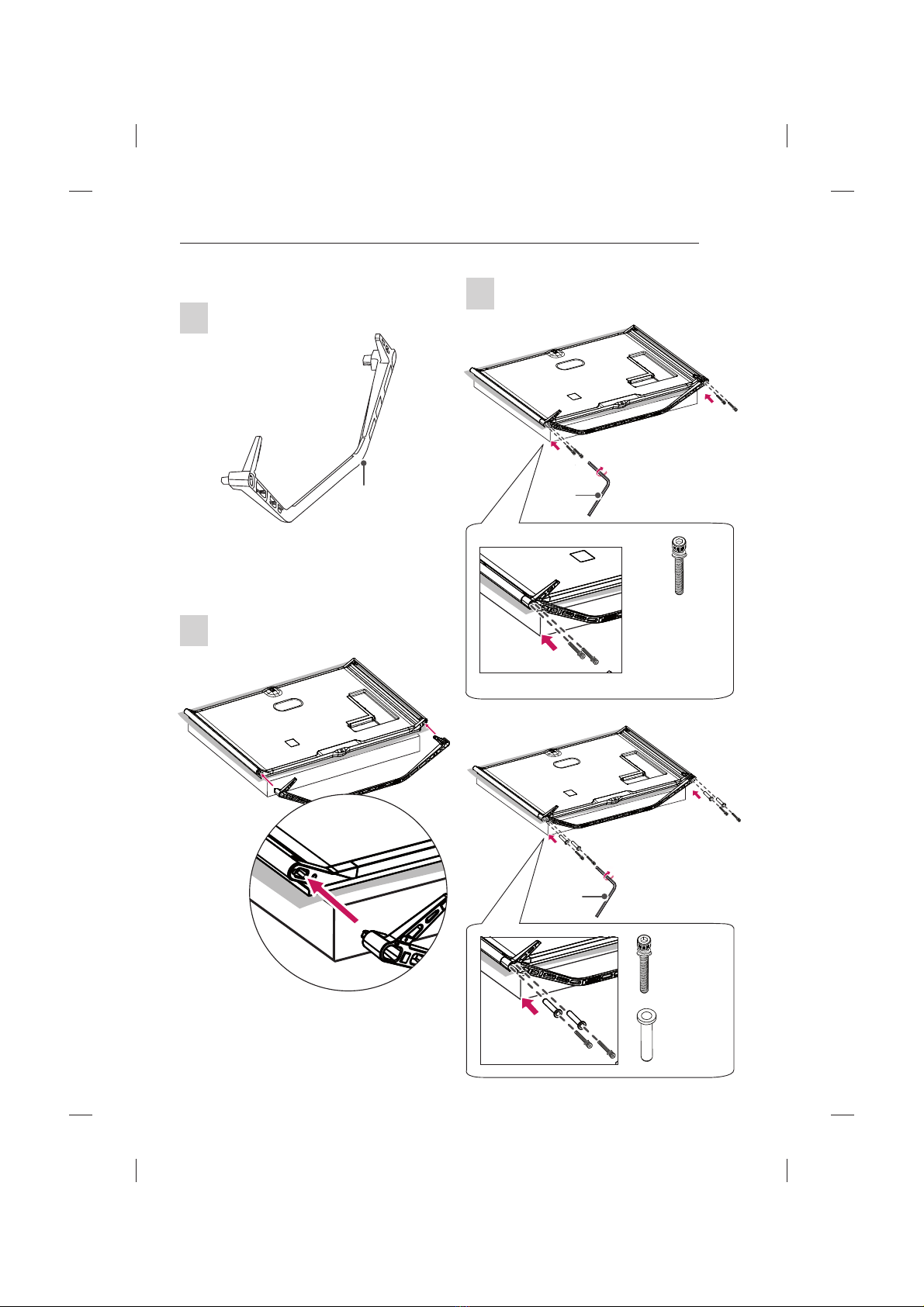
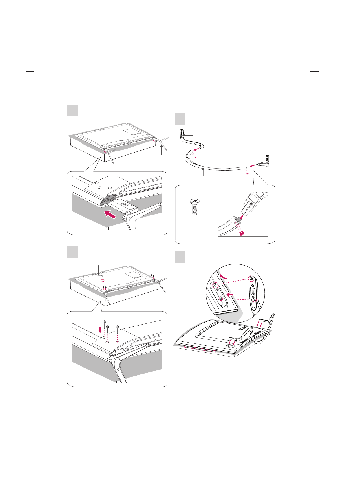
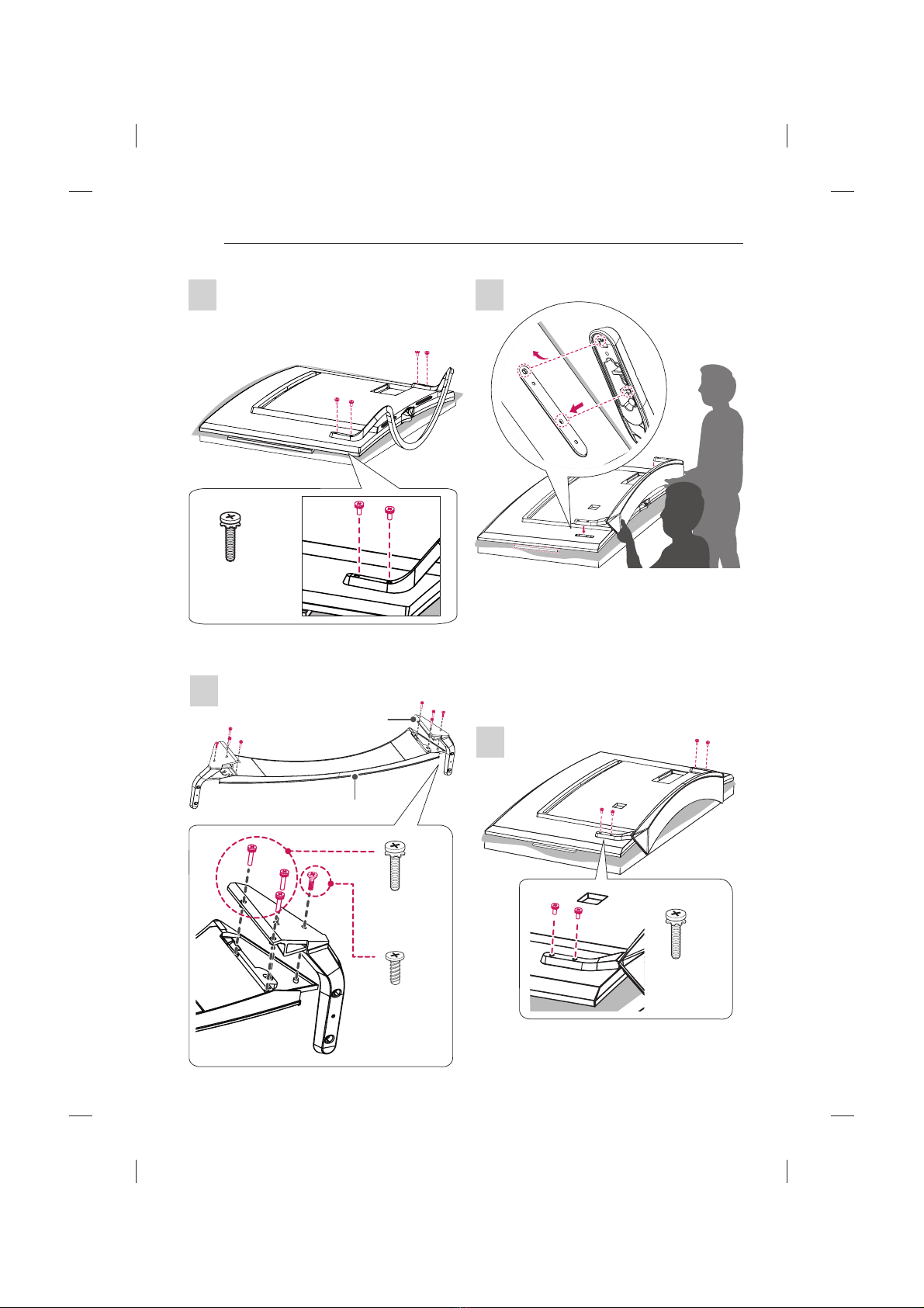
SETTING UP THE TV
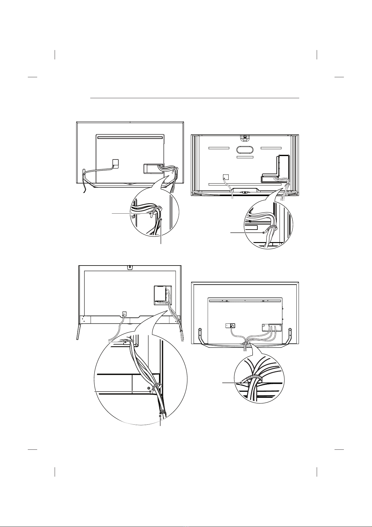
Tidying cables
Image shown may differ from your TV.
1 Gather and bind the cables with the Cable Holder
and the Cable Management.
2 Fix the Cable Management firmly to the TV.
(Only UB85**-ZA, UB93**, UB95**-ZA)
Cable Holder
Cable Management
(Only UB85**-ZD, UB95**-ZB)
Cable Holder
Cable Management
yWhen attaching the stand to the TV set, place
the screen facing down on a cushioned table or
flat surface to protect the screen from scratches.
(Only UB85**, UB93**, UB95**, UB98**)
yMake sure that the screws are inserted correctly
and fastened securely. (If they are not fastened
securely enough, the TV may tilt forward after
being installed.)
Do not use too much force and over tighten the
screws; otherwise screw may be damaged and
not tighten correctly.
CAUTION
yRemove the stand before installing the TV on a
wall mount by performing the stand attachment in
reverse.
yRemove the protective film from the stand base
and then attach the stand body to the stand base.
(Only UC97**)
NOTE