LG
November 2018
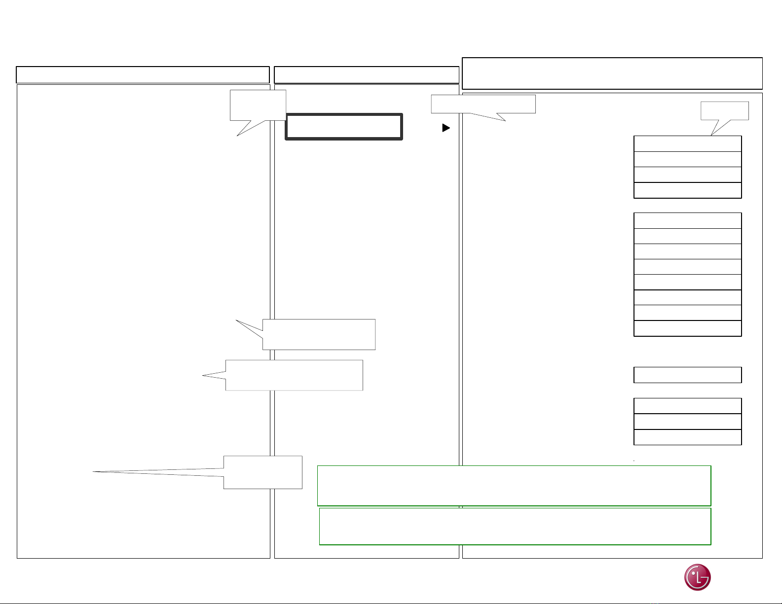
55EG9600 IN-START “Power Off Status” Details (2 of 3) 55EG9600 (2015) In-Start Menu
Page 05
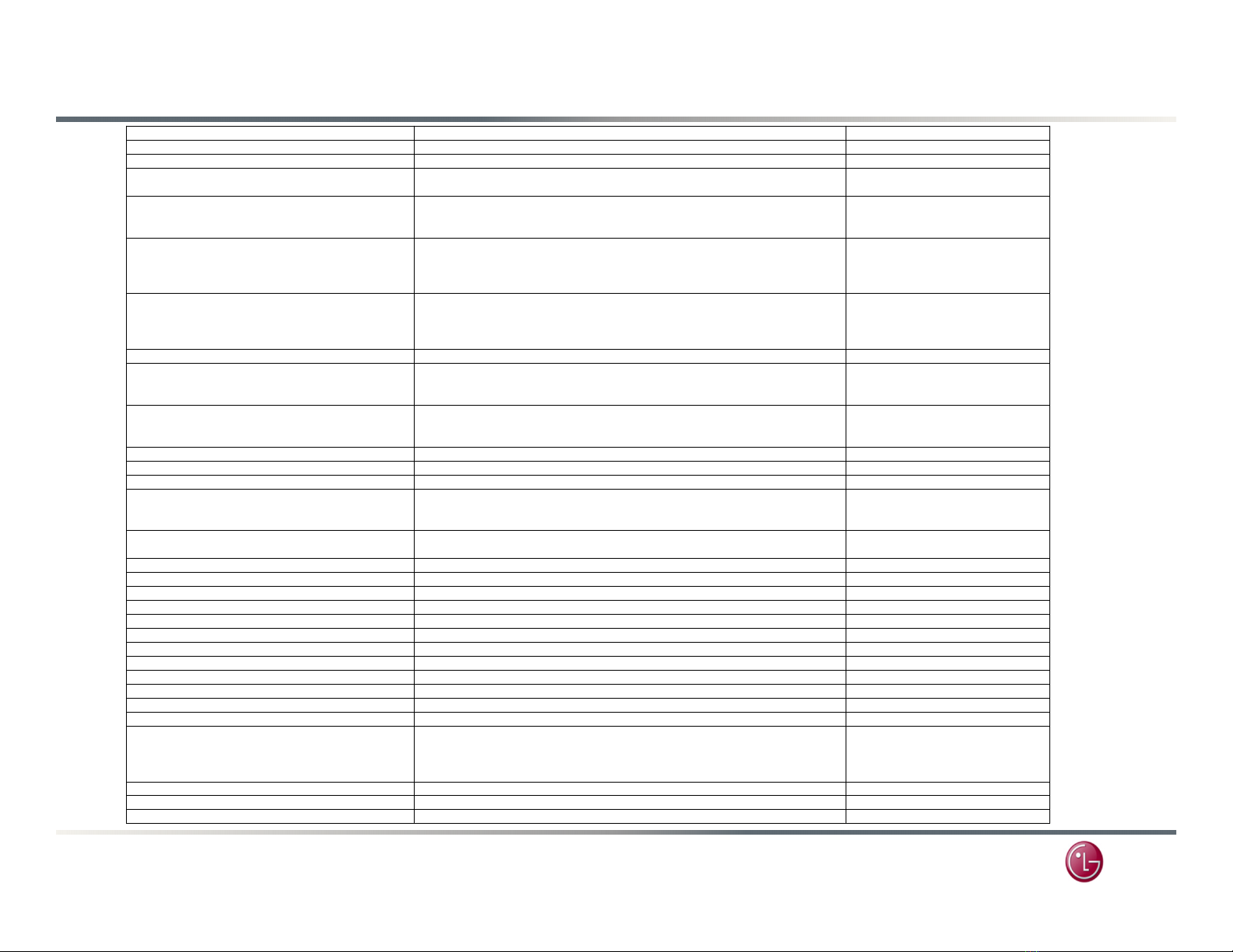
MODE Contents Action
POWER_OFF_BY_NO_POLLING
Power off when receiving no reply from a sub-micom
RESULT: TV power off/on (Reboot)
CONDITION: There is no I2C response from CPU for 15 seconds.
Main, IR, WiFi
POWER_OFF_BY_OFF_TIMER Power off by Off timer None
POWER_OFF_BY_OLED_AM_MODE If the module cable is disconnected in W7 model, the micom is force power off TV. None
POWER_OFF_BY_OLED_COMP_FAIL A failure has been reported to the Micom from the OLED display or Compensation was interupted.
(All OLED webOS Before webOS 3.5) Panel, Main, SW
POWER_OFF_BY_ON_TIMER Power off by On timer
Power off when no remote and local key input for 2 hours after power on by On timer. None
POWER_OFF_BY_ONRF_FAIL RESULT: Reboot
CONDITION: OLED module compensation is running but fails. Panel
POWER_OFF_BY_OVERHEATING power off by overheating (for OLED model) Installation / Panel
POWER_OFF_BY_PLLFAIL RESULT: Micom triggers TV power off/on (reboot), due to Micro stops working.
CONDITION: When power on, there is no reply from the Micro. This can be caused by a sub-Micom. Main, IR, WiFi
POWER_OFF_BY_PNWASHDONE Power off by panel noise wash function complited. (OLED after webOS 3.0) None
POWER_OFF_BY_PNWASHFAIL Power off by panel noise wash function fail case. (OLED after webOS 3.0) Panel / SW
POWER_OFF_BY_PNWASHSTART Power off for starting OLED panel noise function in warm state. (OLED after webOS 3.0) None
POWER_OFF_BY_POWER_BD_PROTECT RESULT: Micom triggers TV power off (for power board safety)
CONDITION: when power board gets overloaded. SMPS, Main
POWER_OFF_BY_POWERONLY Request reset by p-only remote key. (condition: DC On) None
POWER_OFF_BY_POWERSOUND Power off by power off sound function. (When Accessibility, TV Power Sound turned On) None
POWER_OFF_BY_QUICK_START Power off by reboot to suspend function.
When the user turns off the TV, reboot the TV with QSM+ as needed. None
POWER_OFF_BY_REMOTE_KEY Power off by remote key None
POWER_OFF_BY_REMOTE_KEY2 RESULT: Micom force TV power off within 1 second. IR, Keys
POWER_OFF_BY_REQUEST_RESET
Power off by request reset
CONDITION 1: Run ‘Initialization’ through Smart TV setting
CONDITION 2: Run ‘App initialization’.
CONDITION 3: Reset is required for Instart setting is changed.
None
POWER_OFF_BY_RESET
Power off by Micom Reset
CONDITION 1: Run ‘Initialization’ through Smart TV setting
CONDITION 2: Run ‘App initialization’.
CONDITION 3: Reset is required for In-Start setting is changed.
None
POWER_OFF_BY_RESUME_FAIL Power off by resume fail when dc on case.
If occur the resume fail, TV will be rebooted. None
POWER_OFF_BY_RS232C Power off by RS232C command None
POWER_OFF_BY_SIG_DETECT Signal command None
POWER_OFF_BY_SLEEP_TIMER Power off by sleep timer None
POWER_OFF_BY_SWDOWN Power off by software download None
POWER_OFF_BY_TEMPERATURE_SENSOR_ERROR power off by temperature sensor error (OLED and HECTO) Installation / Fan
POWER_OFF_BY_VERIFY_FAIL RESULT: System shut down.
CONDITION: verification for LG application fails. Main
POWER_OFF_BY_VSOVP VS Over Voltage Protect (PDP Only) SMPS, Y, Z
POWER_OFF_BY_VSUVP VS Under Voltage Protect (PDP Only) SMPS, Y, Z
POWER_OFF_BY_WARMCHECK
Power off by warm check thread.
It's normal case. When DC on with warm condition, main SoC run the warm check thread.
If the SoC has nothing to do, TV is power off by warmcheck.
Main
POWER_OFF_BY_WEAVE Power off by IOT device. External