Lindsay Broadband LBON4000 ONU User manual

LBON4000 ONU
User Manual
LBON4000 April 2013

I LBON4000 April 2013
Table of Contents
Section & Description Page
1.0 Product Description…………………………………………….....…1
2.0 Safety Notes….……………………………………………………......2
3.0 Block Diagram…………………………………………………….…..3
4.0 Specifications...............................................................................4
5.0 RF Connector Installation.......................................................….5
6.0 Power Connector Installation......................................................5
7.0 AC Power Director........................................................................6
8.0 General Set Up………………………………………………….…….6
9.0 Forward Path Set Up……………………….………………….…….7
10.0 Reverse Path Set Up……………..………………………….……..8
User Manual
LBON4000
2/4 Port Outdoor Optical Node with AGC
User Manual
LBON4000
1
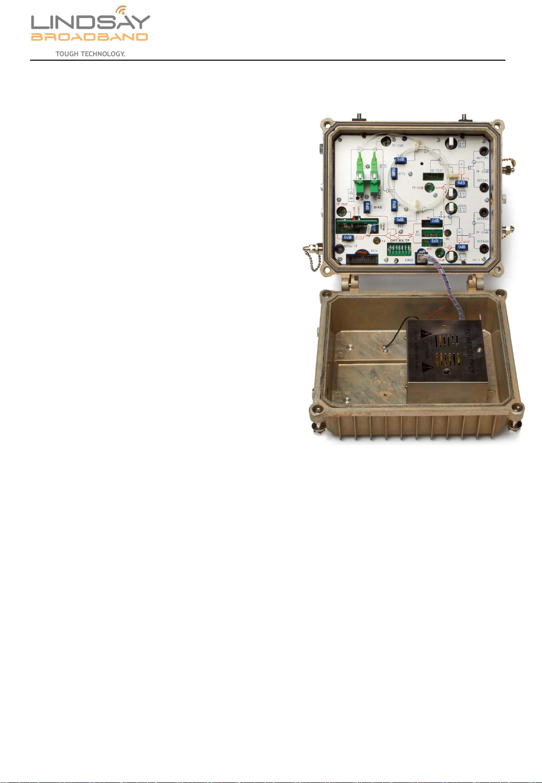
The Lindsay Broadband Inc. LBON4000 is a
hardened outdoor, high output, 2 or 4 output,
optical fiber node capable of up to 52dBmv
with 2 outputs and 48dBmv with 4 outputs at
1002MHz . Advanced GaAs-FET technology,
achieve excellent distortion performance at
High output levels with low power
consumption. LBON4000 is designed to carry
advanced video and data traffic to the HFC
Network (Single Family homes, MDU, Office,
and University locations.
The LBON4000 offers flexibility in choice of
wavelength, laser type and band splits for
maximum application.
FEATURES
•High RF output level 52/48dBmV per Port for 2/4 Ports
•GaAsFET Technology provides Low Distortions and Low power consumption
•Downstream bandwidth: 54/85MHz to 1002MHz; Upstream bandwidth: 5Mhz to 42/65MHz
•Extended optical input level range (-7dBm to +3dBm) for maximum flexibility
•1310, 1550,FP or DFB laser options for return transmitter.
•Built-in microprocessor controlled AGC tracks input optical level changes
•LED display for visual indication of Optical input receive level.
•Separate -20dB RF test ports for forward and reverse directions
•Surge protection on all ports
•Superior heat dissipation, die case aluminum housing
•Efficient Switching Power Supply 40-90VAC
LBON4000 April 2013
NO SERVICEABLE PARTS INSIDE. REFER SERVICING TO QUALIFIED SERVICE PERSONNEL.
2.0 SAFETY NOTES
•The LBON4000 employs an infrared laser device that emits invisible
light, which can permanently damage the retina of an eye.
•Avoid direct exposure to the laser light source.
•Never apply power to this product if the fiber is neither connected nor
terminated.
•Never stare directly into a fiber or at any mirror-like surface that could
reflect light emitted from an un-terminated fiber.
•Never view an active fiber through optical instruments.
2
User Manual
LBON4000
LBON4000 April 2013
3
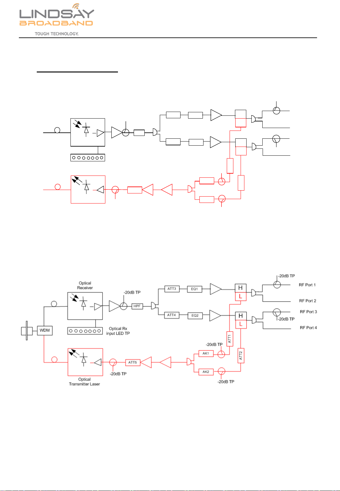
3.0 Block Diagram
HPF
ATT3
ATT4 EQ2
EQ1 H
H
L
L
ATT5
AK1
AK2
ATT2
ATT1
Optical Rx
input LED TP
Optical Rx
input
Optical Tx
out
Optical
Receiver
Optical
Transmitter Laser
-20dB TP
-20dB TP
-20dB TP
-20dB TP
-20dB TP
-20dB TP
RF Port 1
RF Port 3
RF Port 2
RF Port 4
FIGURE 1. Dual Fiber
User Manual
LBON4000
FIGURE 2. Single Fiber
LBON4000 April 2013
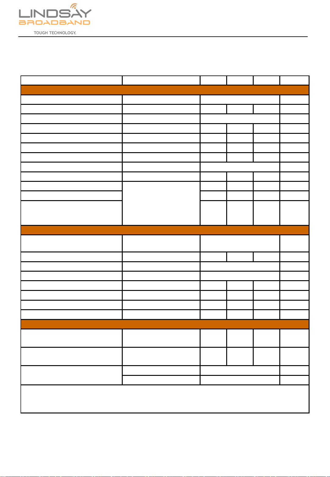
SPECIFICATIONS
4
User Manual
LBON4000
PARAMETER CONDITIONS MIN TYP MAX UNIT
Optical Wavelength nm
Monitor Voltage λ=1550 1 V/mW
Optical Input Power Optical AGC dBm
Optical Input Return Loss 45 dB
Frequency Range (optional) (Note1) 54 1000 MHz
Flatness of Frequency Response f=54 to 1000MHz ±0.75 dB
Output Return Loss 16 dB
Reference Output Level 2 Port / 4 Port dBmV
Slope 0- 18dB adjustable 12 dB
C/N 50 51 dB
CTB -65 dB
CSO -61 dB
Optical Wavelength nm
Optical Output Power Available in 2, 3 or 4mW 2 3 4 mW
RF Input Level dBmV
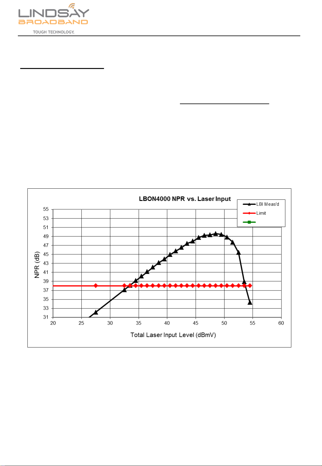
Dynamic Input Range NPR ≥38 dB
Frequency Range Optional 5-65MHz 5 42 MHz
Flatness of Frequency Response f=5 to 42MHz ±0.75 dB
Input Return Loss f=5 to 42MHz 16 dB
Optical Output Return Loss 45 dB
Total Power Consumption (AC) 40-90VAC 30 W
Operating Temperature
Humidity 5% to 95%, non
condensing
-25 60 ℃
Width x Length x Depth in.
Width x Length x Depth mm
241 x 203 x 117
34 -48
Note 1: 42/54MHz; (Other options; 65/85MHz; 85/105MHz)
FORWARD RECEIVER
RETURN TRANSMITTER
GENERAL PARAMETERS
1200 ~ 1600
(-1dBm optical input,
3.5% OMI/ch, 79ch NTSC,
Digital ch above 550MHz
at -6dB offset)
17 - 31
1310, 1550 or CWDM
-6 to +1
52 / 48
Physical Dimensions
9.5 x 8.0 x 4.6
LBON4000 April 2013

5
RF Connector Installation:
1. All RF connectors including the power port connector are standard
KS-type connectors. Refer to Figure 3.
1. Using a ½-inch wrench, remove port covers from RF ports and power
port on the housing base.
2. The center conductor seizure screws (Phillips screw) are located
through the module. Loosen, but do not remove the seizure screw.
3. Measure the stinger to verify that it is 0.8 inches (20mm). Refer to
Figure 4.
5. If you are going to apply shrink tubing to weatherproof the finished
connection, slip a section of shrink tube over the end of the cable
now.
6. Insert the KS connector and cable to the Housing base and tighten
connector. KS connectors should be tightened per manufacturer’s
specifications.
7. Using a Philips screw driver tighten the seizure screw.
8. Position the shrink tubing over the connector and apply heat to
shrink it in place.
0.8 in
(20mm)
CAUTION! AC voltages in the range of 40 to 90 V AC. Shut down external
AC power before connecting or disconnecting power cables to the node.
1. The LBON4000 requires AC input power between 40 and 90 VAC. AC
power is brought into the Node through the dedicated power port.
2. Follow “RF Connection Installation” section to install Power cable.
Power Cable Installation:
Figure 3
Figure 4
User Manual
LBON4000
LBON4000 April 2013

6
AC Power Director:
1. AC HFC power can be sent to remote locations via the output ports depending on the configuration of the
power port jumpers.
2. Each RF output port has a plug-in AC Power Director/Jumper.
3. Check the system maps to determine which power directors should be inserted in a power passing
position. Install each power director as required. Refer to Figure 5.
General Set-up:
1. Test the optical input power on the system downstream cable with an optical power meter to verify
that it is within the optical input range specification.
2. Clean the optical connectors on the node and on the service cable then connect them together,
matching the system downstream cable to the node receiver and the system upstream cable to the
laser transmitter.
3. Verify that the total upstream RF signal level (from all ports) is within the node’s specified input range,
then connect the coaxial cable to the node’s RF In/Out F-port.
4. The LBON4000 must be grounded, Use a split-bolt grounding stud or your system preferred ground
attachment to ground the Node housing to earth ground. Install the split-bolt grounding stud on the
base housing. Refer to Figure 6.
• For a strand-mounted, install the grounding stud in the threaded hole on the base.
• For a pedestal or surface mounted Node, remove one of the two strand mount brackets,
and install the grounding stud in the threaded hole.
Loosen the top nut and insert the grounding cable. (You may need to remove the nut to insert cable.
With the grounding cable installed, tighten the top nut to secure the cable.
5. Apply HFC power to the node through power port (40 –90VAC). Verify that the Return Transmitter
“Normal” LED and the “Opt. RX TP” LEDs illuminate.
Figure 5
Figure 6
User Manual
LBON4000
LBON4000 April 2013

7
Forward Path Set-up): (Refer to Figure 7)
1. Verify that the received optical level indicated on the “Optical Rx LED “ strip is as expected.
2. The Optical node comes factory set with attenuators already in place. The attenuator used to
establish the output tilt is factory set with a 9dB attenuator. That will produce approximately 12-13db
of tilt between 54 and 1000MHz. That indicates there is approximately 3 –4dB of built in equalization.
3. While monitoring the forward Out1 test point (-20dB), and with a 0dB pad in ATT3 position, place
desired attenuator value into EQ1 for desired output tilt.
4. Countinuing to monitor Out1 test point (-20dB), adjust pad value in ATT3 position for the desired
output level. Verify that the level is correct at both ends of the bandwidth. Output 1 & 2 are now set
up in the Forward Path.
5. Repeat steps 3 & 4 for Output 3 & 4, using test point on Out3, and ATT4 and EQ2 positions.
Downstream
Incoming Fiber
ATT4; Fwd RF
attenuator
ATT3; Fwd RF
attenuator
EQ2; Fwd
Equalizer For
Port 3&4; Tilt set
with attenuator
EQ1; Fwd Equalizer For Port
1&2; Tilt set with attenuator
Optical RX LED
Display TP
Figure 7
User Manual
LBON4000
LBON4000 April 2013
8
Reverse Path Set-up:
1. Take an account of all the upstream services going into all 4 ports of the LBON4000. Refer to
Figure 8 to Calculate the Total Return RF level. To help with this calculation, or to set the levels
based on an equal power per Hertz basis, please visit www.lindsaybroadbandinc.com
Resources Tab for a spreadsheet calculator. The Total RF return level at the input to the laser
should be 34 –50dBmv @ NPR=38dB. This can be checked at the Return test point (-20dB) at
the Return Transmitter.
Tip
plan for the additional RF power of future services when setting the optimum reverse input
level. Then the levels won’t have to be re-adjusted to avoid laser clipping when those services are
added later.
Figure 8
User Manual
LBON4000
LBON4000 April 2013

9
Reverse Path Set-up:
3. The LBON4000 comes factory set with 2db pads in Position AK1 and AK2. Do Not change value.
Refer to Figure 9.
4. Return Path attenuators ATT1 and ATT2 are adjusted to match as close as possible the RF return
input levels between Ports 1&2 and Ports 3&4, based on system knowledge of the incoming Return
RF levels from each of the 4 ports.
5. Adjust ATT5 pad value to insure total return level to the laser is 34 –50dBmv. Measure the RF levels
at the node input using the Rev T.P. and remember that it is 20dB below the actual signal level.
Please note that the test point is located after the reverse pad, so any adjustments made using the
pad can be read directly from the T.P. port.
Return RF -20db TP
before laser
Return laser
transmitter
ATT5; Return RF
attenuator
ATT1; Return RF
attenuator for
Port 1&2
ATT1; Return RF
attenuator for
Port 3&4
Upstream/Return
Fiber
Figure 9
User Manual
LBON4000
LBON4000 April 2013
Table of contents


