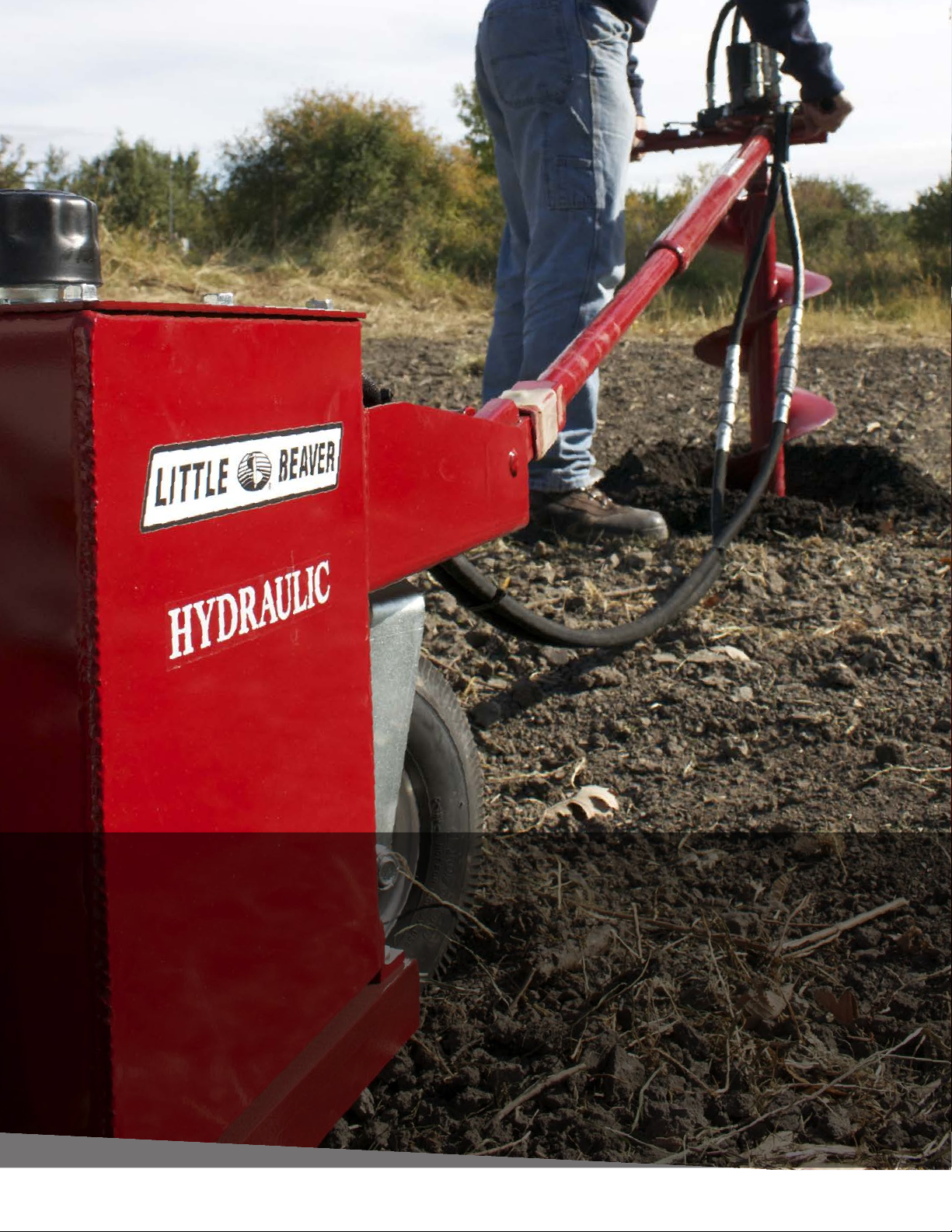
LITTLE BEAVER Hydraulic Earth Drill User manual

Hydraulic Earth Drills
OPERATORS MANUAL
WITH MAINTENANCE AND PARTS INFORMATION

SAFETY ALERT SYMBOL
The symbol shown above is used to call your attention to instructions concerning your personal safety.
WATCH THIS SYMBOL — It points out important safety precautions. It means — ATTENTION! BECOME
ALERT! YOUR PERSONAL SAFETY IS INVOLVED!
Read the message that follows and be alert to the possibility of Personal Injury or Death!
lllllllllllllllllllllllllllllllllllllllllllllllllllllllllllllllllllllllllllllllllllllllllllllllllllllllllllllllllllllllllllllllllllll
1 YEAR LIMITED WARRANTY
For 1 year from purchase, LITTLE BEAVER, INC. will replace for the original purchaser,
free of charge, any part or parts, found upon examination by any factory authorized service
center, or by the factory at Livingston, Texas, to be defective in material or workmanship or
both. If your equipment can not be repaired, it will be replaced. All transportation charges
on parts submitted for replacement under this warranty must be borne by purchaser.
There is no other express warranty.
Implied warranties, including those of merchantability and fitness for a particular purpose,
are limited to 1 year from purchase and to the extent permitted by law. Any and all implied
warranties are excluded. This is the exclusive remedy and liability for consequential damages
under any and all warranties are excluded to the extent exclusion is permitted by law.
*Notice: Engines are warrantied by the manufacturer of the engine. See separate engine
warranty enclosed.
lllllllllllllllllllllllllllllllllllllllllllllllllllllllllllllllllllllllllllllllllllllllllllllllllllllllllllllllllllllllllllllllllllll
MACHINE SERIAL NUMBER
There are two serial numbers for your hydraulic earth drill, one for the handle and one for the power
source. The handle serial number is located on the bottom side of the handle. The power source serial
number is located on the rear side of the hydraulic reservoir. For your convenience, when requiring
service or parts information, refer to these numbers and your model numbers. Record the serial
numbers, model numbers, engine make and date of purchase in the space provided below:
Handle Serial Number: Power Source Serial Number:
Handle Model Number: Power Source Model Number:
Engine Make:
Date of Purchase:
1004
Page O-1
WARNING: The Engine Exhaust from this product contains chemicals known
to the State of California to cause cancer, birth defects or other reproductive harm.
l

Page 0-2
TABLE OF CONTENTS
OPERATORS MANUAL
Page #
O-1 Safety Alert, Warranty and Machine Information
O-2 Table of Contents
O-3 Safety Instructions and Specifications
O-4 Maintenance and Lubrication Instructions
O-5 Wheel and Torque Tube Assembly
O-6 & 7 Operating Instructions
O-6 Handle and Auger Operation Information
O-7 Extension and Accessories
O-8 Decal Location
O-9 Troubleshooting
PARTS MANUAL
Page #
P-1 & 2 Tank & Carrier Assembly
P-3 Pump, Filter and Sight Guage Assemblies
P-4 Torque Tube and Wires
P-5& 6 One-Man Handle
P-7 & 8 Two-Man Handle
P-9 & 10 Anchor Handle
P-11 & 12 Auger Information
P-13 Extensions & Adaptors
Hydraulic Notes
Prices for Hydraulic Parts and Augers
Inside Back Cover...Torque Information and Conversion Chart
0196

SAFETY INSTRUCTIONS
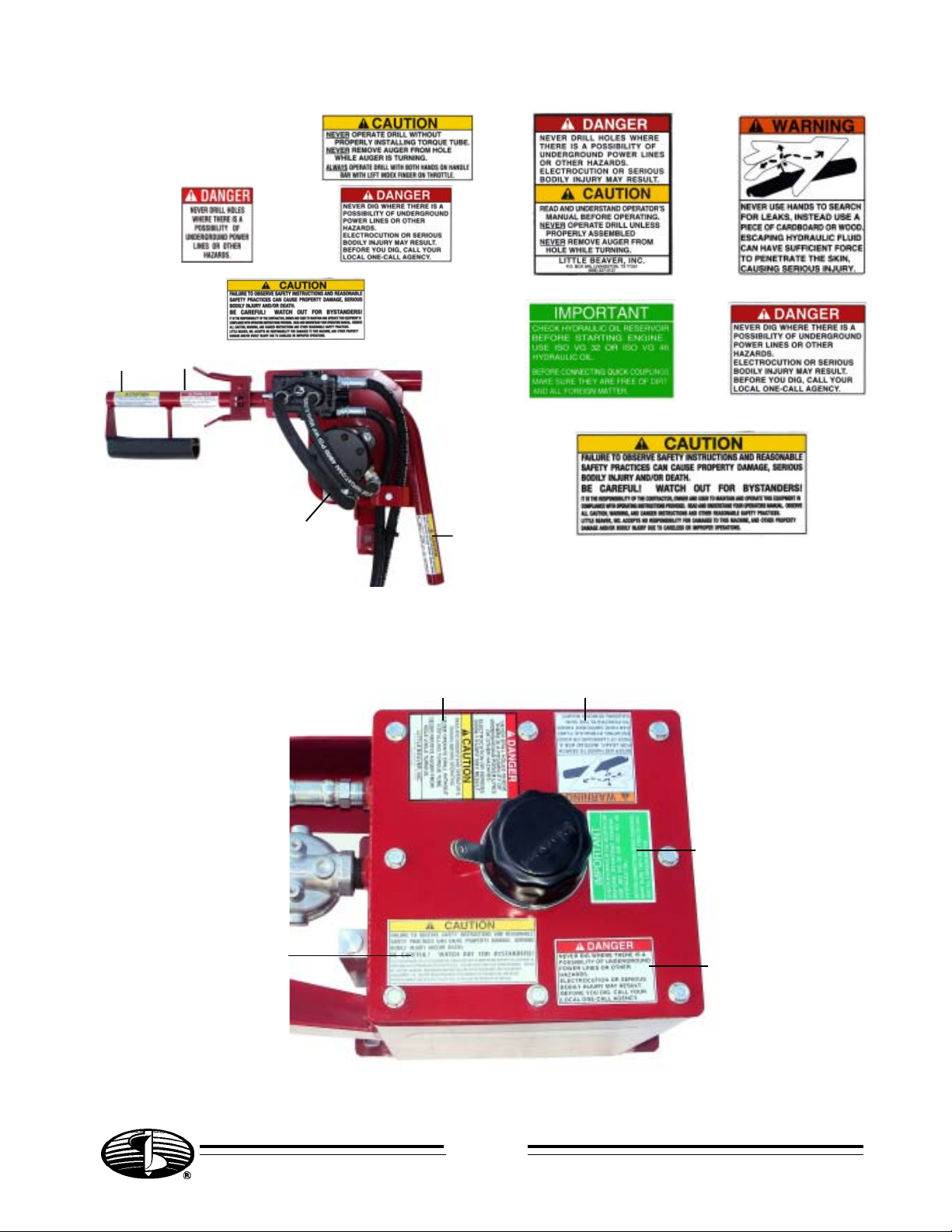
DANGER: Failure to observe safety instructions and reasonable safety practices can
cause Property Damage, Serious Bodily Injury and/or Death. BE CAREFUL!! WATCH OUT
FOR BYSTANDERS!!
DANGER: NEVER run engine inside building or enclosed area. Exhaust gases contain carbon
monoxide, an odorless and deadly poison.
DANGER: NEVER drill holes where there is a possibilityof underground power cables or other
hazards. The exact location of underground services must be determined prior to drilling.
Inadvertent severing of telephone, fiber optic or CATV transmission cable, or damage to sewer
pipe is costly; RUPTURING OF GAS OR WATER LINES CAN CAUSE SERIOUS BODILY INJURY AND/
OR DEATH. COMING INTO CONTACT WITH BURIED POWER LINES CAN CAUSE SERIOUS BODILY
INJURY, SEVERE BURNS, AND/OR ELECTROCUTION. Call local utility companies or your local "One-
Call" number at least 48 hours before digging and have underground utilities marked.
WARNING: Never use hands to search for leaks. Instead, use a piece of cardboard or wood.
Escaping hydraulic fluid under pressure can have sufficient force to penetrate the skin, causing
serious injury. Before disconnecting lines, be sure to relieve pressure. Before applying pressure,
be sure connections are tight and fittings and hoses are not damaged.
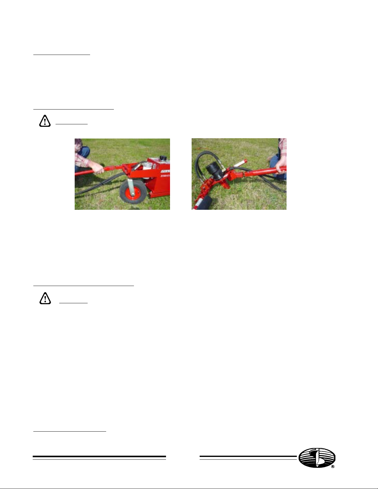
WARNING: Augers are not to be used as anchoring devices.
CAUTION:
1. READ and understand this operator’s manual and the operator’s manual for the engine.
2. NEVER Operate drill without correctly installing torque tube.
3. NEVER Remove auger from hole while auger is turning.
4. NEVER Operate auger at less than full throttle.
5. NEVER Operate drill with damaged auger or other damaged or missing parts.
6. KEEP Hands, Feet and Clothing away from moving parts while engine is running.
7. KEEP All safety shields and devices in place.
8. MAKE Certain everyone is clear before operating the machine.
9. KEEP Leg pad against leg while drilling to maintain safe control.
10. WEAR SAFETY GLASSES.
11. KEEP Bystanders away from work area.
12. SHUT OFF Engine to adjust, service or clean the machine.
NOTICE
It is the responsibility of the contractor, owner and user to maintain and operate the Earth Drill in
compliance with operating instructions provided. Observe all listed safety instructions and other
reasonable safety practices. LITTLE BEAVER, INC. accepts no responsibility for damages to this machine,
and other property damage and/or bodily injury due to careless or improper operations.
LITTLE BEAVER, INC. does not recommend or condone any modifications which would eliminate the torque
tube.
LITTLE BEAVER, INC. does not recommend use of replacement hydraulic motors which would result in
auger shaft torque greater than 400 ft.-lbs. If greater torque is required, please consult factory.
LITTLE BEAVER, INC. reserves the right to make changes in design and changes for improvements upon
its product without imposing any obligation upon itself to install the same upon its products theretofore
manufactured.
Your operators manual offers recommendations for prolonged and satisfactory service.
SPECIFICATIONS
11 HP Honda, 11 HP Briggs & Stratton OR 11 HP Wisconsin
6 GPM @ 2000 PSI
100 Micron Suction Screen
10 Micron Replaceable Return Line Filter
5 Gallon Hydraulic Reservoir
Page O-3
0196

MAINTENANCE AND LUBRICATION INSTRUCTIONS
NOTE: All engines and hydraulic reservoirs are shipped WITHOUT oil.
ENGINE: The engine is shipped without oil or gasoline. Refer to the manufacturers instructions for
proper procedures and recommended fluid.
HYDRAULIC FLUID AND FILTER: The hydraulic reservoir should be filled to the top of the sight gauge
with hydraulic oil before attempting to start the engine. Most premium grade, mineral based oil with anti-
wear (AW) and anti-foaming additives are suitable. The recommended fluid for normal temperature
operation is ISO VG 46 grade fluid. In colder climates use ISO VG 32 grade and in warmer climates use
ISO VG 68 grade fluid. The hydraulic oil and return line filter (Part # 30280) must be kept clean at all
times, and should be changed after the first 15 hours of operation. The filter and oil should be changed
every three months or after 100 hours of operation; whichever comes first.
NOTE: The hydraulic fluid and engine crankcase oil levels should be checked prior to each
days use.
IMPORTANT: All nuts, fasteners, and fittings must be kept tightened. If the engine or tank
mounting bolts are allowed to loosen, premature coupling and/or pump wear may result.
CAUTION: Escaping hydraulic fluid under pressure can have sufficient force to penetrate the
skin, causing serious injury. Before disconnecting hydraulic lines, be sure to relieve
pressure. Before applying pressure, be sure connections are tight and fittings, pipes and
hoses are not damaged. Use a piece of cardboard or wood, rather than hands, to search for
leaks. If injured by escaping fluid, see a doctor at once. Serious infection or reaction can
develop if proper medical treatment is not administered immediately.
KEEP all hydraulic lines away from moving parts.
HYDRAULIC OIL LEAKAGE
If any hydraulic oil leakage is encountered, shut down the power source and relieve the hydraulic
pressure by moving the throttle valve in both directions. Check and tighten the screw-on fittings on the
end of each hose. If the leakage persists, it may be necessary to replace the associated hose assembly.
If one of the Quick Disconnect fittings is the source of leakage, the quick disconnect coupling should
be replaced. If the throttle valve is leaking around the spool (shaft), you may replace the seal kit (Part
# 30275-2).
NOTE: To obtain maximum performance from power source, minimum hose size
recommended is 3/8".
HYDRAULIC HOSE ASSEMBLY REPLACEMENT
WARNING: For power source serial numbers from H-0001 through H-3252, do not exceed
the following maximum hose assembly lengths. Longer hose assemblies may allow the torque tube
to uncouple, causing serious personal injury.
If replacement hose assemblies are required, the maximum overall length of the pressure/return
hose assembly on the handle is 36". The maximum overall length of the pressure hose assembly on
the power source is 74 1/4" and the maximum overall length of the return hose assembly on the
power source is 68".
EXCESSIVE HEATING
Excessive heating is caused by placing too much down pressure on the auger which causes the oil
pressure to reach relief pressure. Oil flowing over the relief valve generates the heat.
DECAL LOCATION
The decals which are provided with your machine are shown at the rear of this manual. The decals shown
should be in the locations as described. If any of the decals are missing or illegible, order replacement
decal kit # 30181-D# and install before operating the machine.
Page 0-4
0196

TORQUE TUBE ASSEMBLY
WARNING: Properly install torque tube to prevent serious injury from kick-back torque while
drilling.
The torque tube consists of one end with a 1-1/2" square female fitting and a 1-1/4" square male
fitting on the other end. Attach the larger female end of the torque tube to the power source bracket
as shown in figure 1. Attach the other male end to the handle as shown in figure 2. Be sure to align the
snap button with the mating hole provided and check to be sure the snap buttons are securely snapped
into place.
WHEEL ASSEMBLY
Attach a wheel to each end of the rear axle using a 3/4" flat washer and securing with a 1/8" x 1"
cotter key. Attach the front wheel to the swivel bracket using one 3/4" x 5-1/2" cap screw, two spacers,
and one 3/4" lock nut.
OPERATION
BEFORE STARTING THE ENGINE,_Be sure that:
1.) Engine is properly prepared to Manufacturer’s specifications. Note: Engines with “Oil
Guard” protection must be filled with oil to full mark on dipstick or to point of
overflowing to allow the engine to start.
2.) Hydraulic Reservoir is filled to top of sight gauge.
3.) The torque tube is properly attached.
4.) There is no auger connected to the handle.
5.) The Quick Disconnect fittings are correctly coupled.
6.) The Torque Tube has engaged the Kill Switch at the Power Source.
TO START THE ENGINE: Set the choke lever to the “ON” position and pull the starter rope. The engine
should start after 2 or 3 pulls. Set the choke lever to the “OFF” position and allow the engine to warm-
up for 2 or 3 minutes.
0196
DANGER: NEVER run engine inside building or enclosed area. Exhaust gases contain carbon
monoxide, an odorless and deadly poison.
Figure 2
Figure 1
Page O-5

AFTER THE ENGINE HAS WARMED UP, Insert the auger into the drive adaptor on the bottom of the
handle. Make sure the snap button and hole provided in the adaptor are aligned and the button snaps
securely into place. Hold the handle so your left index finger and thumb can operate the throttle (pull
with the index finger for forward rotation, push with the thumb for reverse). NOTE: ONLY use reverse
to free the auger if it becomes lodged in the ground. Grasp the right handle bar with your right hand.
Stand so the auger is straight up-and-down and is properly positioned to dig your hole (see figures 3
& 4). Note the safety instructions in this manual and on the machine’s decals.
FIGURE 3 FIGURE 4
IMPORTANT: Keep the back as vertical as possible by bending the legs, as required, during the
operating and lifting procedure.
ONE-MAN HANDLE
Always keep the leg pad against leg to maintain safe and stable control during operation.
TWO-MAN HANDLE
The operator controlling the throttle lever must alert the other operator prior to engaging the earth drill
to ensure readiness. Both operators must distribute even pressure on the auger, as required, to maintain
uniform drilling.
`
MAKE certain everyone is clear before operating the machine.
KEEP hands, feet and clothing away from moving parts while engine is running.
START THE AUGER TURNING By pulling the throttle lever in completely. Always allow the auger to turn
at full speed and let it cut its way into the soil.
IMPORTANT: When digging in soft soil, hold up slightly on auger. In hard pan, apply pressure, but not
enough to stall the auger or slow it down significantly. The auger works best when it turns at full speed.
IF THE AUGER STALLS repeatedly or slows down significantly; stop the auger by releasing throttle lever,
slightly lift up on auger, start auger by pulling throttle lever, and allow the auger to turn at full speed
while slowly lowering it to bottom of hole.
NEVER Remove auger from hole while auger is turning.
When the desired depth is reached, stop the auger by releasing the throttle lever. Then pull the auger
completely out of the hole.
IMPORTANT: Keep the back as vertical as possible by bending the legs, as required, during the operation
and lifting procedure.
Page O-6
DANGER: NEVER drill holes where there is a possibilityof underground power cables or other
hazards. The exact location of underground services must be determined prior to drilling.
Inadvertent severing of telephone, fiber optic or CATV transmission cable, or damage to sewer
pipe is costly; RUPTURING OF GAS OR WATER LINES CAN CAUSE SERIOUS BODILY INJURY AND/
OR DEATH. COMING INTO CONTACT WITH BURIED POWER LINES CAN CAUSE SERIOUS BODILY
INJURY, SEVERE BURNS, AND/OR ELECTROCUTION. Call local utility companies or your local
"One-Call" number at least 48 hours before digging and have underground utilities marked.
0196

0196
AUGER EXTENSIONS
If greater hole depths are required, extensions
may be used with the auger. After the auger
has reached its maximum depth, stop the
auger and disconnect the drive adaptor from
the auger which remains in the hole. Connect
the extension to the auger as shown in figure
5. Connect the drive adaptor to the extension
and continue to dig the hole.
When the desired depth is reached, stop the auger and disconnect the drive adaptor from the
extension then remove the extension(s) and auger from the hole.
When working with cutting blade, point and auger flighting; be careful not to be cut by
sharp edges.
FIGURE 5
ATTACHMENTS:
Several attachments are available for your LITTLE BEAVER Earth Drill; including both west and dry
type horizontal boring kits and a drill chuck adaptor which allows you to use a wood bit. Refer to
the specific operating instructions supplied with the attachment. If these become lost or misplaced,
replacements may be obtained from the factory.
Page O-7
CUTTING BLADE
Check the cutting blade (Item A, Figure 6) on the auger fre-
quently. If it becomes dull, it may be reversed to use the other
cutting edge. If the outside of the blade wears even with the
auger flighting, replace the blade or rebuild it with a hard
surfacing rod. This is very important to reduce auger flighting
wear and damage. The point (Item B, Figure 6) should be re-
placed when it loses its cutting shape.
FIGURE 6
A
B

Page O-8
For Decal Kit, Order Part # 30181-D#
1110
DECAL LOCATION -A
-C
-D
-B
-E
F-
- G
C
B
D
AH-
- I
F
G
IH
E

Page O-9
1207
TROUBLESHOOTING
TROUBLE CAUSE
Engine will not start 1) Torque tube is not connected at power source
2) Engine stop switch is in "off" or "O" position
3) Low fuel level in gas tank
4) Low oil level in "Oil Guard" or "Oil Alert" equipped engines
5) Spark plug fouled
Starter rope pulls hard, 1) Quick disconnect couplings are not fully connected. Push
with more resistance together and rotate collar 1/4 turn.
than usual
Cannot connect or 1) Foreign matter clogging auger adaptor
disconnect auger 2) Spring and button in top of auger is bent or broken
Auger turns too slowly 1) Too much downward pressure or binding on side of hole. Hold
and will not dig back if necessary to allow auger to turn at full speed.
2) Bent linkage between control level and valve. With engine off,
ensure that neither lever touches handle bar when moved to full
forward or reverse position.
Auger turns but will not dig 1) Foreign matter collected around point
2) Point or blade is dull
3) Wrong blade type for soil condition. Contact your dealer or factory
for Little Beaver carbide blade
Auger with extension will 1) Auger or extension bent or running out of line
not dig 2) Number of extensions exceeds capacity of machine
Hydraulic oil and/or hoses 1) It is normal for the hoses and reservoir to be warm to the touch.
overheats If it is very hot, consult your dealer or factory.
Auger turns when engine idles 1) Valve or linkage is binding. Do not use. Consult your dealer or factory.
Problems not listed in table 1) Consult your dealer or factory.

TANK AND CARRIER ASSEMBLY
Page P-1
0196
20 -
- 15
- 16
- 17
------32
- 37
- 34
- 9
- 10
- 16
- 6
- 11
19 -
- 7
- 5
/
12 /
13
- 21
- 23
- 14
- 7
5 -
\
26
31
\
30
\
29
\
-10
- 2
- 3
- 4
------33
25 -
27 -
- 28
8 -
\
36
- 24
- 18
- 22

ITEM PART # DESCRIPTION QTY
2 30100 Pressure Hose - 74 1/4" max. overall length 1
2 30111 Return Hose - 68" max. overall length 1
3 30250-H* Quick Disconnect Coupling, Female 1
4 30251-H* Quick Disconnect Coupling, Male 1
5 3002-A Cap Screw, Handle, Caster & Engine Mounting 6
6 30252 Handle, Front 1
7 3012-2 Screw - 3/8" x 1" GR 5 4
8 30198 Spacer, Handle - 5/16" x 5/8" 2
9 3012-3 Lock Washer - 3/8" 6
10 9027-KEP Nut w/ Lock Washer - 3/8" 6
11 30253-A Swivel Wheel Mount, Albion 1
12 30155-A Axle, Swivel - 3/4" x 6" Hex Screw 1
13 30351 Spacer, Swivel Wheel - 3/4" ID x 1 1/8" 2
14 9096 Nut, Axle - 3/4" 1
15 3012-1T Screw, Tank Top - 5/16"-18 x 3/4" GR 2 8
16 3002-C Lock Washer - 5/16" 14
17 30254 Tank Top 1
18 30255 Tank 1
19 30256-H Carrier 1
20 3002-KEP Nut - 5/16"-18 2
21 30257 Handle Grip 2
22 30163 Cotter - Wheel 1/8" x 1" 2
23 30164 Washer, Wheel - 3/4" Flat 2
24 30348 Wheel, 12" - 3/4" Bore 3
25 3007-9 Kill Switch 1
26 9084-1 Spacer 1
27 9058 Spring & Button 1
28 30280*** Filter 1
29 30281 Filter Base 1
30 30282 Bushing 1
31 30283 Fitting 1
32 30312 Street Ell - 3/4" 1
33 30317 Diffuser, Oil Return Pipe 1
34 30313-11 Shim, 11 Ga - .120" **
30313-14 Shim, 14 Ga - .083" **
30313-16 Shim, 16 Ga - .065" **
30313-18 Shim, 18 Ga. - .049" **
35 30313-1 Shim Kit - 2 Shims of each size ( 8 total) 1
36 30159 Magnet Plug 1
37 30318 Nut, Engine Mounting - 5/16"-18 Lock Nut 4
*Power Source with SN#1675 and lower order complete set shown above.
**Quantity and Size may vary.
***Replacement Filter cross reference numbers are as follows:
Zinga #AE10, Ripley #DP75210, Amback #S-28 or Fram #P1653A
Page P-2
WARNING: For power source serial numbers from H-0001 through H-3252, do not exceed the
following maximum hose assembly lengths. Longer hose assemblies may allow the torque
tube to uncouple, causing serious personal injury.

/
19
PUMP, FILTER AND SIGHT GAUGE ASSEMBLIES
4
3
28
13
/
-11
7-
6-
5-
10-
12-
/
8/
9
/
21 /
23 24-
22
/
20
/
/
25
/
26
/
29
/
27
/
18
6
| 2
/
30
23
/
ITEM PART # DESCRIPTION QTY
2 30260 Cap & Strainer Assembly 1
3 30262 Sight Guage Assembly 1
4 30172 Coupling Guard Assembly 1
5 3012-2 Screw - Guard 3/8" x 1" 2
6 3012-3 Lock Washer - Guard 3/8" 2
7 30154 Nut - Guard 3/8" 2
8 30315 Bushing #5406-8-6 1
9 30316 Fitting #5603-6-6-6 1
10 30270-R Relief Valve 1
11 30291 Hose - Pump to Tank - 11" 1
12 30286 Fitting #6805-10-NWO 1
13 30263-D2 Dowty Pump with key, SAE-A 2-Bolt Flange 1
16 30310 Nipple 3/4" x 2 1/2" 2
17 30266 Suction Filter 1
18 4019 Key - Pump 1
19 30292-2 Gasket - Dowty Pump - SAE-A Flange (goes inside the tank) 1
20 30267-58 Coupling - Pump End, Dowty - 5/8" Bore 1
21 30269 Spider 1
22 30268 Coupling - Engine End 1" Bore (Honda & B&S) 1
30268-W Coupling - Engine End 1 1/8" Bore (Wisconsin) 1
23 30171 Set Screw 2
24 4081 Key - Engine End 1
25 30295 Bolt - 3/8" x 1 1/2" GR 5 2
26 30174 Washer - 3/8" with Neophreme Seal 2
27 30154 Lock Nut - 3/8" Nylon Insert 2
28 30263-D2A Dowty Pump Assembly (2 bolt mounting) 1
30314-D Seal Kit, Dowty Pump 1
29 30293 Ring, Dowty Pump Tank 1
30 30294 O-Ring #110 (goes outside tank) 2
31 30298 Fitting, #6905-12-12-NWO 1
Page P-3
042004
-16
\
17
31
\
Inside Tank
TankWall

TORQUE TUBE ASSEMBLY
ITEM PART # DESCRIPTION QTY
1 9058-1 Button Shield 1
2 9092-M One piece Torque Tube 1
3 9058 Spring & Button 1
4 9084-1 Spacer 1
5 30200 Kill Switch Wire (BIC) 1
6 30200-HW Kill Switch Wire (Honda & Wisconsin) 1
7 3007-5 Plastic Tie 5
8 30201 Wire Loom 1
- 5
- 6
- 8
- 7
4
/
1
/
3
/
2
/
Page P-4

ONE-MAN HANDLE
1101
-7
9
/
12 -
14 -
5 -
10 -
- 18
- 17
- 27
- 20
- 28
8 -
13 -
- 16
26 -
22 -
21 -
- 25
\
19
- 15
6 -
3 -
2 -
\
8
4 -
Page P-5
23--
I
29
30--
11--
24--
31--

ITEM PART # DESCRIPTION QTY
2 30102-A Hose-Valve to Power/Valve to Return, 36" max. overall length 2
3 *30250-H Disconnect Coupling-Female 1
4 *30251-H Disconnect Coupling-Male 1
5 30115 Hose-Valve to Motor 15 1/2" 1
30120-A Hose-Valve to Motor 19 1/2" 1
NOTE: SN H-163 & lower order Part #30103
6 30296 Fitting-Pipe Swivel-Female (O-Ring) 2
30287 Fitting-NPT 2
7 5076 Cap Screw 1/4" x 2" USS-Valve Mounting 2
8 30188 Pushnut, Locking Washer 2
9 30275 Throttle Valve 1
30275-2 Seal Kit (Valve)
10 9026-KEP Nut 1/4" KEP (Nut w/Lock Washer) 2
11 10304 Washer, 1/4" Standard 1
12 30178-A Throttle Linkage 1
13 30179 Cotter Key 3/32" x 5/8" 3
14 30180-A Throttle Lever 1
15 30181-A One-Man Handle ONLY 1
16 9034 Leg Pad 1
17 3010-9 Screw 5/16" x 2"-Hose Clamp 1
18 30183 Clamp-Hose 1
19 3002-KEP Nut 5/16" KEP (Nut w/Lock Washer) 1
20 30191 Hydraulic Motor w/2 bolt flange-220 RPM (103-1035 ) 1
30191-S2 Hydraulic Motor w/2 bolt flange-150 RPM (103-1036 ) 1
21 6532 Cap Screw 1/2" x 2" Gr 5 for 2-Bolt Motor 2
22 35312 Lock Washer 1/2" 2
23 30272 Adaptor, Heavy Duty, Hardware Included 1
24 30010 Screw, Socket Head 1/4"-20 x 1" with locking plug 1
25 9058-1 Button Shield 1
26 30158 Nut, Nylon Lock, 1/2" 2
27 30198 Spacer 5/16" x 5/8"-Hose Clamp 1
28 30182 Key 1
29 9021 Set Screw 1/4"-20 x 1/4"-Adaptor 1
30 10520 Washer, Williams, 3/8" 1
31 9025 Washer, Split Lock, 1/4" 1
30162-B Seal Kit (Motor # 103-XXXX-005/006)
30162-D Seal Kit (Motor # 103-XXXX-008, 009, 010)
*Power Source with SN#1675 and lower order complete set shown as above.
*Handle SN#5562 and lower order CO-2BF# as replacements.
WARNING: For power source serial numbers from H-0001 through H-3252, do not exceed the
following maximum hose assembly lengths. Longer hose assemblies may allow
the torque tube to uncouple, causing serious personal injury.
Page P-6
ONE-MAN HANDLE

TWO-MAN HANDLE
1101
11 -
- 8
12
\
- 7
16 -
24 -
- 16
25
\
- 31
- 18
- 9
13 -
26
/
- 29
-33
19 -
20 -
30-
17 -
23
/
32
/
- 28
- 15
- 14
- 6
- 3
- 4
26
\
- 27
17
\
- 5
- 2
Page P-7
- 10
- 34
21--
-- 35

TWO-MAN HANDLE
WARNING: For power source serial numbers from H-0001 through H-3252, do not exceed the
following maximum hose assembly lengths. Longer hose assemblies may allow
the torque tube to uncouple, causing serious personal injury.
ITEM PART # DESCRIPTION QTY
2 30102-A Hose-Valve to Power/Valve to Return, 36" max. overall length 2
3 *30250-H Disconnect Coupling-Female 1
4 *30251-H Disconnect Coupling-Male 1
5 30120-A2 Hose-Valve to Motor 24" 1
30120-L Hose-Valve to Motor 22 1/2" 1
NOTE: SN H-163 & lower order Part #30105
6 30296 Fitting-Pipe Swivel-Female (O-Ring) 2
30287 Fitting, NPT 2
7 30275 Throttle Valve 1
30275-2 Seal Kit (Valve)
8 5076 Cap Screw 1/4" x 2" USS GR 5 2
9 9026-KEP Nut 1/4" KEP (Nut w/ Lock Washer) 2
10 10304 Washer, 1/4", Standard Flat 1
11 30179 Cotter Key 3/32" x 5/8" 1
12 30180-A Throttle Lever 1
13 30190 Two-Man Handle-Spider 1
14 3002 Bolt 5/16" x 1 1/2" USS GR 2-Hose Bracket 1
15 30183 Clamp-Hose 1
16 30188 Pushnut, Locking Washer 2
17 3002-KEP Nut 5/16" KEP (Nut w/ Lock Washer) 7
18 30191 Hydraulic Motor w/ 2 bolt flange-220 RPM (103-1035 ) 1
30191-S2 Hydraulic Motor w/ 2 bolt flange-150 RPM (103-1036 ) 1
30278 Hydraulic Motor w/ 2 bolt flange-60 RPM (101-1040 ) 1
19 6532 Bolt 1/2" X 2" GR 5-Motor Mounting 2
20 35312 Lock Washer 1/2" 2
21 30272 Adaptor, Heavy Duty, hardware included 1
22 30010 Cap Screw 1/4"-20 x 1" w/Locking Plug 1
23 30271-A Handle-Hose Anchor 18" 1
24 30178-A Throttle Linkage 1
25 30273-A Handle-Throttle Mount 18" 1
26 30274-A Handle-Bare 18" 2
27 3010-9 Screw 5/16" x 2" USS GR 2-Handle 4
28 30198 Spacer 5/16" x 5/8"-Hose Clamp 1
29 9058-1 Button Shield 2
30 30158 Nut, Nylon Lock, 1/2" 2
31 30182 Key 1
32 30194 Handle Grip-Two-Man Handle 4
33 9021 Set Screw-Adaptor 1
34 10520 Washer, Williams, 3/8" 1
35 9025 Washer, Split Lock, 1/4" 1
30162-B Seal Kit (Motor # 103-XXXX-005/006)
30162-D Seal Kit (Motor # 103-XXXX-008, 009, 010)
*Power Source with SN#1675 and lower order complete set shown as above.
*Handle SN# 5562 and lower order CO-2BF# as replacements.
Page P-8

1101
- 16
10 -
13 -
14 -
8 -
12 -
\
8
7 -
- 9
- 20
- 28 - 17
- 18
- 27
5 -
6 -
- 15
26 -
22 -
21 - \
19
- 25
4 -
3 -
2 -
23--
I
29
30--
11--
24--
31--
ANCHOR HANDLE
Page P-9

ANCHOR HANDLE
ITEM PART # DESCRIPTION QTY
2 30102-A Hose-Valve to Power/Valve to Return, 36" max. overall length 2
3 **30250-H Disconnect Coupling-Female 1
4 **30251-H Disconnect Coupling-Male 1
5 30115 Hose-Valve to Motor 15 1/2" 1
30120-A Hose-Valve to Motor 19 1/2" 1
NOTE: SN#163 & lower order Part #30103
6 30296 Fitting-Female (O-Ring) 2
30287 Fitting, NPT 2
7 5076 Cap Screw 1/4" x 2" USS GR 5-Valve Mounting 2
8 30188 Pushnut, Locking Washer 2
9 30275 Throttle Valve 1
30275-2 Seal Kit (Valve) 1
10 9026 Nut 1/4" KEP (Nut w/ Lock Washer) 2
11 10304 Washer, 1/4" Standard 1
12 30178-A Throttle Linkage 1
13 30179 Cotter Key 3/32" x 5/8" 1
14 30180-A Throttle Lever 1
15 30276-A Anchor Handle ONLY 1
16 9034 Leg Pad 3
17 3010-9 Set Screw 5/16" x 2" GR 2-Hose Clamp 1
18 30183 Clamp-Hose 1
19 3002-KEP Nut 5/16" KEP (Nut w/ Lock Washer) 1
20 30278 Hydraulic Motor w/ 2 bolt flange-60 RPM (101-1040 ) 1
30191-S2 Hydraulic Motor w/ 2 bolt flange-150 RPM (103-1035 ) 1
30191 Hydraulic Motor w/ 2 bolt flange-220 RPM (103-1036 ) 1
21 6532 Bolt, 1/2" x 2" GR 5-MotorMounting 2
22 35312 Lock Washer 1/2" 2
23 30272 Adaptor, Heavy Duty, includes hardware 1
24 30010 Screw, Socket Head, 1/4"-20 x 1" with locking plug 1
25 9058-1 Button Shield 1
26 30158 Nut, Nylon Lock, 1/2" 2
27 30198 Spacer 5/16" x 5/8" 1
28 30182 Key 1
29 9021 Set Screw-Adaptor 1
30 10520 Washer, Williams, 3/8" 1
31 9025 Washer, Split Lock, 1/4" 1
*30161 Seal Kit 60023 (Motor # 101-XXXX-007)
*30161-A Seal Kit 60036 (Motor # 101-XXXX-005)
30162-B Seal Kit (Motor # 103-XXXX-005/006)
30162-D Seal Kit (Motor # 103-XXXX-008, 009, 010)
*When ordering Flange or Seal Kit, you must specify motor serial number in order to obtain correct parts.
**Power Source with SN#1675 and lower order complete set as shown above.
*Handle SN#5562 and lower must order CO-2BF# as replacements
WARNING: For power source serial numbers from H-0001 through H-3252, do not exceed the
following maximum hose assembly lengths. Longer hose assemblies may allow
the torque tube to uncouple, causing serious personal injury.
1101
Page P-10
Other LITTLE BEAVER Drill manuals