Loctite 3D Printing EQ Washer DW11 User manual

1
2551224 3D Printing EQ Washer DW11
Operating Manual

2
Table of Contents
1 Please Observe the Following ................................................................................................... 4
1.1 Emphasized Sections ........................................................................................................... 4
1.2 For Your Safety ..................................................................................................................... 4
1.3 Material .................................................................................................................................. 4
1.4 Unpacking and Inspection .................................................................................................. 5
1.5 Items supplied ...................................................................................................................... 5
1.6 Features ................................................................................................................................. 6
1.7 Usage ..................................................................................................................................... 6
2 Description ................................................................................................................................... 7
3 Technical Data ............................................................................................................................. 8
4 Overview ...................................................................................................................................... 8
4 Installation .................................................................................................................................... 9
4.1 Environmental and Operating Conditions .............................................................................. 9
4.2 Electrical Connection .............................................................................................................. 10
4.3 Turn on Machine ..................................................................................................................... 10
5 Operation .................................................................................................................................... 10
5.1 Main UI Instruction ................................................................................................................. 10
5.2 Setting Page............................................................................................................................. 12
5.3 Operation .................................................................................................................................. 13
5.3.1 Process .............................................................................................................................. 13
5.3.2 To Run ............................................................................................................................... 13
5.3.3 Change Cleaner ................................................................................................................ 14
6 Application Hints ....................................................................................................................... 14
6.1 Mount PR10’s Print Head ................................................................................................. 15
6.2 Bracket Mounting ............................................................................................................... 16
6.3 Mounting Bracket ............................................................................................................... 17

3
7 Troubleshooting ......................................................................................................................... 18
7.1 Lid Switch ............................................................................................................................ 18
7.1.1 Locating the Lid Switch .................................................................................................. 18
7.1.2 Indicator for Lid Switch ................................................................................................... 18
7.2 Replace Tank ...................................................................................................................... 19
7.3 Ball Screw and Limit Switch ............................................................................................. 20
7.4 Electrical Panel ................................................................................................................... 20
7.5 Basic Troubleshooting ....................................................................................................... 21
8 Care and Maintenance ............................................................................................................. 21
9 Dimension........................................................................................................................................ 22
10 Diagrams ....................................................................................................................................... 23
11 Warranty ..................................................................................................................................... 23
12 Declaration of Conformity ........................................................................................................ 25

4
1 Please Observe the Following
1.1 Emphasized Sections
Warning!
Refers to safety regulations and requires safety measures that protect the operator
or other persons from injury or danger to life.
Caution!
Emphasizes what must be done or avoided so that the unit or other property is not
damaged.
Notice:
A notice gives recommendations for better handling of the unit during operation or
adjustment as well as for service activities.
1.2 For Your Safety
For safe and successful operation of the unit, read these instructions
completely. If the instructions are not observed, the manufacturer can assume no
responsibility.
Do not expose the connecting cable to heat, oil, or sharp edges.
Make sure the Unit stands stable and secure.
Use only original equipment replacement parts.
Always disconnect the power supply before servicing the unit.
Observe general safety regulations for the handling of chemicals such as
Loctite® adhesives and sealants. Observe the manufacturer’s instructions as stated
in the Safety Data Sheet.
While under warranty, the unit may be repaired only by an authorized Loctite
service representative.
1.3 Material
Warning!
Not for use with IPA. For use with Loctite Cleaner C, IDH# 2491820 only.

5
1.4 Unpacking and Inspection
Carefully unpack the Loctite® 3D Printing EQ Washer DW11 and examine the items
contained in the carton. Inspect the unit for any damage that might have occurred in
transit. If such damage has occurred, notify the carrier immediately. Claims for
damage must be made by the consignee to the carrier and should be reported to the
manufacturer.
CAUTION! Please refer to the picture. Handle and lift machine carefully.
1.5 Items supplied
1.5.1 3D Printing EQ Washer DW11
1.5.2 Equipment Manual
1.5.3 2 pcs of Power Cord, EU and US.
1.5.4 2 pcs of basket. (Mounted inside tank)
1.5.5 Manual Pump

6
1.6 Features
1.6.1 Bidirectional agitation
1.6.2 Dual bath design
1.6.3 Adjustable cleaning cycle timer for each bath
1.6.4 Automatic z axis up/down
1.6.5 Touch screen user interface with color display
1.6.6 Loose part basket or build head mount
1.6.7 3 agitation speeds
1.6.8 Cleaner pot life timer
1.6.9 Large volume reservoir
1.7 Usage
The Loctite® 3D Printing EQ Washer DW11 is a high-performance wash station
specifically designed and engineered for washing 3D printed parts created using
Loctite 3D Printing resins.

7
2 Description
The Loctite® 3D Printing EQ Washer DW11 is a high-performance wash station
specifically designed and engineered for washing 3D printed parts created using
Loctite 3D Printing resins.
Loctite 3D Printing EQ Washer DW11 is an automatic cleaning unit that users can
place the Loctite PR10 printer build platform directly into the Wash Station, set the
wash time, and initiate the automatic washing of the 3D printed parts. The Loctite®
3D Printing EQ Washer DW11 utilizes a rotating impeller to circulate the cleaner
bidirectionally to achieve maximum cleaning. A universal wash basket is also
provided for loose parts if a Loctite build head is not used.
Loctite 3D Printing EQ Washer DW11 is a 2-bath process used in conjunction with
Loctite Cleaner C. The first bath contains the Loctite Cleaner and the second bath
contains DI water for a final rinse. Each bath has an individual timer setting for
optimizing cleaning and rinsing times. At the start of the cycle, the build head or
basket is automatically lowered into the bath and cleaning begins. At the end of the
cycle the build head or basket is automatically removed from the bath. The build
platform or basket is manually moved to the second bath for automatic rinsing.
Washer DW11 also provides cleaner’s pot life timer which can be set based on
individual application parameters. The timer will remind users when it is time to
change the cleaner bath.
8
3 Technical Data
Dimensions (L x H x W): 476 x 589 x 419 (mm)
Total weight: lbs. (Kg) 45 kg
Operating voltage: 100-240 VAC 50/60Hz
Power consumption: 300 Watts
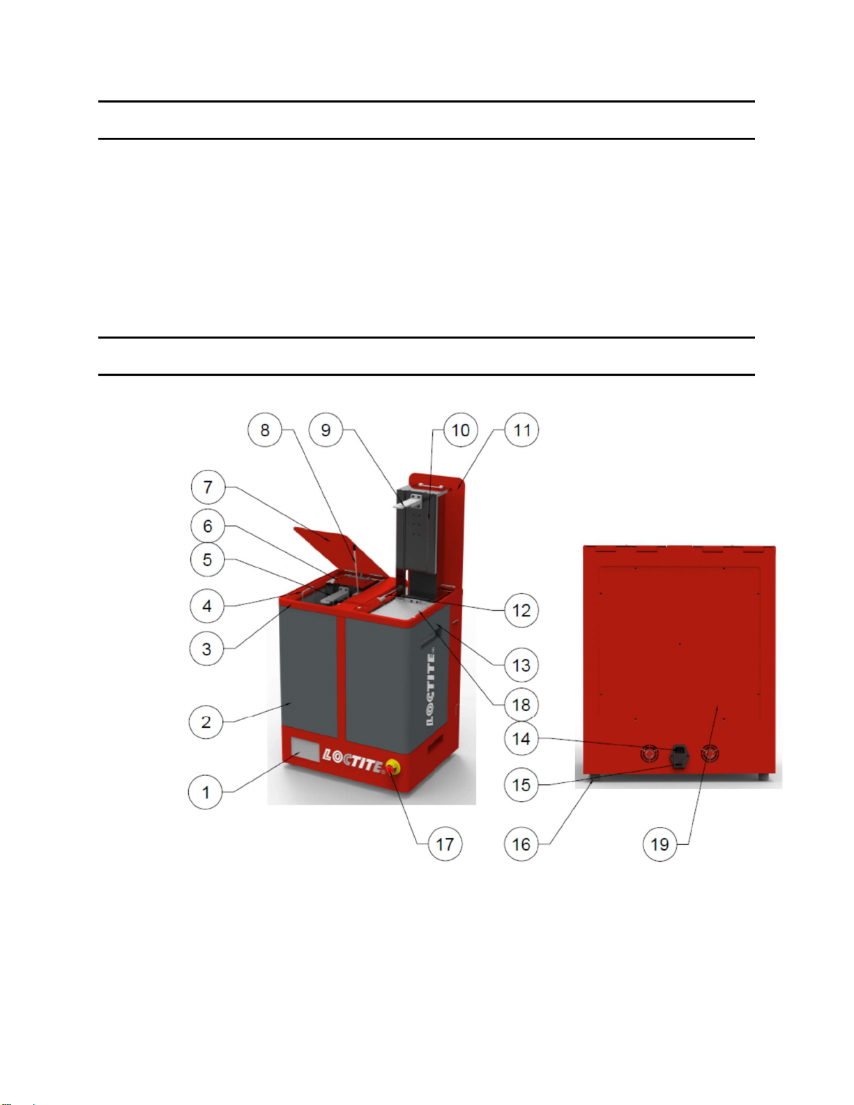
4 Overview
1. UI Screen
2. Left Tank
3. Lid Holder
4. Catch Screen

9
5. Build Platform/Basket Bracket
6. Elevator
7. Left Lid
8. Bonnet Support Rod
9. Build Platform/Basket Bracket
10. Elevator
11. Right Lid
12. Bonnet Support Rod
13. Right Tank
14. Power Inlet
15. ON/OFF Switch
16. Leveling Foot
17. EMO Button
18. Catch Screen
19. Rear Panel
4 Installation
Before using the equipment for the first time check it carefully for signs of external
damage. If any shipping damage is found DO NOT USE THE EQUIPMENT – return it
to your supplier immediately.
4.1 Environmental and Operating Conditions
- The equipment should be installed in a dry, well ventilated and dust-free place.
- To ensure proper ventilation, install the unit at a distance of at least 100 – 150 mm from
a wall or neighboring object.

10
4.2 Electrical Connection
Plug the AC power cord into No. 14 Power Inlet, which located in rear side of machine.
4.3 Turn on Machine
- Make sure emergency stop button (No. 17) is released.
- Press ON/OFF switch (No. 15) to power on
5 Operation
5.1 Main UI Instruction
1. Page Button #1—To enter control page of left tank
2. Page Button #2—To enter control page of right tank
3. Status Indicator #1—left tank’s status.
4. Status Indicator #2—right tank’s status.
5. Cleaning Timer Bar

11
6. Pot Life Reset Button
7. Pot Life Timer Bar
8. “Setting” Button—Enter Setting Page
9. “Stop” Button
10. “Pause” Button
11. “Start” Button
12. Lift Control Button
There are 2 position for elevator: Up (ready position) and down (working position).
When elevator is in down position, the button shows . Press button, elevator
will go to up position.
When elevator is in UP position, the button shows . Press button, elevator will
go to down position.
13. Time & Date
Time and data are shown in this area. Press and hold for 3s, operator can edit time
and date.
12
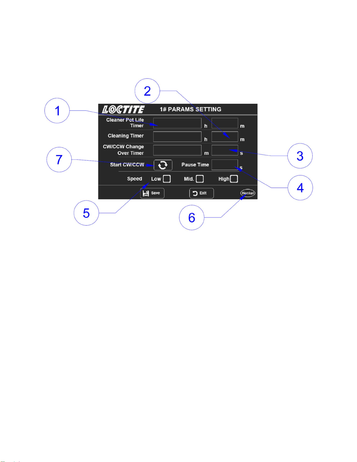
5.2 Setting Page
1. Cleaner Pot Lift Timer—Set cleaner’s pot life.
2. Cleaning Timer—Set timer for each cleaning cycle.
3. CW/CCW Change Over Timer—Set time for agitation direction changing.
4. Pause Time—Set pause time between CW/CCW changing. Default setting is 4s
5. Speed Selection—Define agitation speed.
There are 3 speed levels:
Low: 100 rpm
Mid: 120 rpm
High: 140 rpm.
6. Press the Henkel logo can enter setting 2 page.
7. Change over CW/CCW--For example, when set to CW, washer will work at CW
direction when start.

13
5.3 Operation
5.3.1 Process
Press “START”:
Step 1. Elevator will go down to working position
Step 2. Impeller starts.
When cycle finishes:
Step 1. Impeller stops
Step 2. Elevator goes to up position.
Press “STOP”:
Step 1. Impeller stops
Step 2. Elevator goes to up position.
5.3.2 To Run
Step 1. If elevator is in working position, press or “STOP” button to raise it
to up position.
Step 2. Mount build platform or basket on the bracket.
Step 3. Set cleaning timer
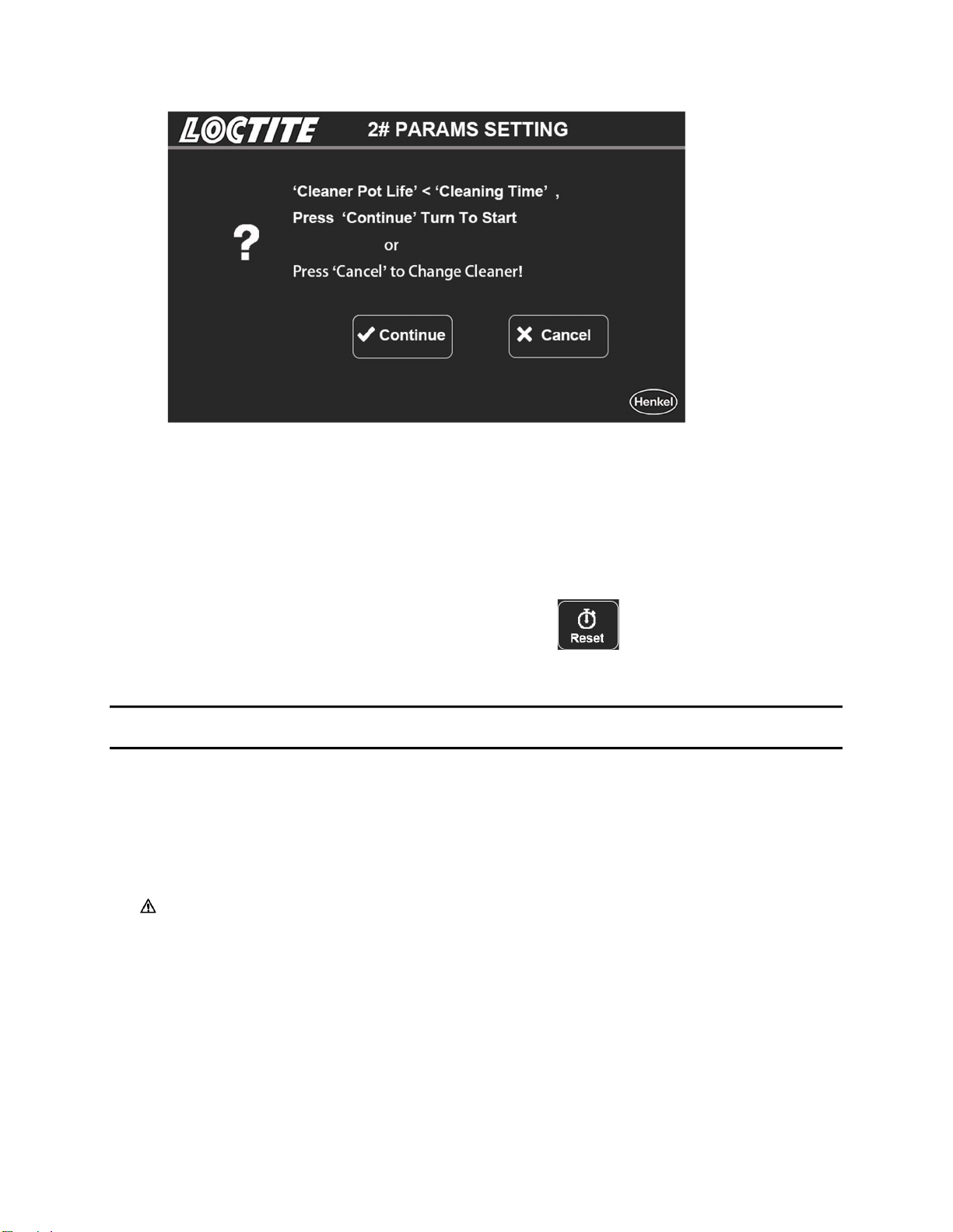
Step 4. Please be noted, if “Cleaning Timer” > “Cleaner Pot Life”, below message will
be shown on screen. Press “Continue” to run, or “Cancel” to exit cleaning cycle, and
change cleaner.
14
Step 5. Elevator goes to up position when cleaning finished.
5.3.3 Change Cleaner
When Cleaner Pot Timer reaches 0, please change cleaner.
After refilling cleaner, please click Pot Life Reset button to reset timer.
6 Application Hints
As with all adhesives and cleaners, performance depends on conditions of use.
Suggestions or recommendations contained herein are for guidance only, since
actual conditions of use are outside the supplier’s control.
Before proceeding with any repair or maintenance operation disconnect the Loctite®
3D Printing EQ Washer from the main electricity supply.

15
6.1 Mount PR10’s Print Head
Refer to below picture, PR10’s print head can be mounted on bracket directly.

16
6.2 Bracket Mounting
Unit in mm

17
6.3 Mounting Bracket
There are 4 screws to mount bracket.
There are 10 screw holes on elevator to mount bracket. Bracket can be mounted on 4
levels.

18
7 Troubleshooting
7.1 Lid Switch
7.1.1 Locating the Lid Switch
Refer to the below picture. The lid switch is located below each lid.
7.1.2 Indicator for Lid Switch
There is indicator for lid on UI screen.
When Lid is
Closed
When Lid
Open/Switch
error

19
7.2 Replace Tank
1. Open lids, refer to below picture, find the 2 screws and remove them.
2. Refer to below picture, follow step 1,2,3, remove tank bath.

20
7.3 Ball Screw and Limit Switch
Refer to the below picture. Open rear panel
7.4 Electrical Panel
Electrical panel is located on the bottom of machine. Please refer to the below
picture.
This manual suits for next models
1
Table of contents


