manuals.online logo
Brands
  1. Home
  2. •
  3. Brands
  4. •
  5. Milnor
  6. •
  7. Washer
  8. •
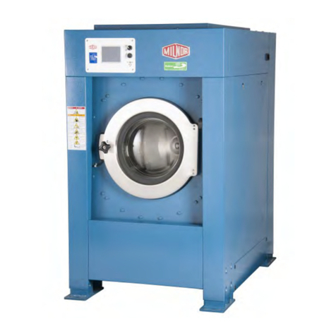
  9. Milnor 48040F7 Series Manual

Milnor 48040F7 Series Manual

Published Manual Number/ECN: MPI4840FAE/2004036N
• Publishing System: TPAS
• Access date: 1/19/2004
• Document ECN's: Exact
Installation and Service—
48040F7x
PELLERIN MILNOR CORPORATION POST OFFICE BOX 400, KENNER, LOUISIANA 70063-0400, U.S.A.
Please Read
About the Manual Identifying Information on the Cover
The front cover displays pertinent identifying information for this manual. Most important, are
the published manual number (part number) /ECN (date code). Generally, when a replacement
manual is furnished, it will have the same published manual number, but the latest available ECN.
This provides the user with the latest information applicable to his machine. Similarly all
documents comprising the manual will be the latest available as of the date the manual was
printed, even though older ECN dates for those documents may be listed in the table of
contents.
When communicating with the Milnor factory regarding this manual, please also provide the
other identifying information shown on the cover, including the publishing system, access date,
and whether the document ECN’s are the latest available or exact.
References to Yellow Troubleshooting Pages
This manual may contain references to “yellow pages.” Although the pages containing
troubleshooting procedures are no longer printed on yellow paper, troubleshooting instructions, if
any, will be contained in the easily located “Troubleshooting” chapter or section. See the table of
contents.
Trademarks of Pellerin Milnor Corporation
The following, some of which may be used in this manual, are trademarks of Pellerin Milnor
Corporation:
Ampsaver®Dye-Extractor®Gear Guardian®Milnet®Staph-Guard®
Autolint®Dyextractor®Hands-Off®Milnor®System 4®
Auto-Purge®E-P Express®Hydro-Cushion®Miltrac System 7®
Autovac E-P OneTouch®Mildata®Miltron Totaltrol®
CBW®E-P Plus®
Comments and Suggestions
Help us to improve this manual by sending your comments to:
Pellerin Milnor Corporation
Attn: Technical Publications
P. O. Box 400
Kenner, LA 70063-0400
Fax: (504) 469-1849
Table of Contents
for MPI4840FAE/2004036N
48040F7x
Page Description Document/ECN
1 Chapter 1: Installation
2 Installation and Service Safety for Suspended
Washer-Extractors and Centrifugal Extractors MSINA405AE/2000215V
7 Guards & Covers BMP020028/2002226V
10 Safety Placard Use and Placement 48040F7J,F7W
6836F5J,F5W BMP020115/2003444V
12 Safety Placard Use and Placement ISO 48040F7J,F7W
6836F5J,F5W BMP020116/2003444V
14 Safety Placard Use and Placement 48040F7B,F7N
6836F5N BMP020125/2003444V
16 Safety Placard Use and Placement 48040F7B,F7N
6836F5N BMP020126/2003444V
18 Footguard Assembly BMP020037/2002226V
19 Tilt Safety Stands BMP020036/2003295V
20 48040Fxx Washer Extractor Installation BIIFLI01/20020730
25 Shipping Bolts and Brackets BMP020035/2002226V
27 Avoiding Damage from Allied Remote Chemical
Delivery Systems BIWUUI03/20030306
32 About the Forces Transmitted by Milnor Washer-Extractors BIWUUI02/20001108
35 Chapter 2: Service and Maintenance
36 Service Connections BIIFUI01/20020911
39 Preventive Maintenance BIIFUM01/20030311
47 Fastener Torque Requirements MSSM0101CE/9906AV
66 Servicing Disc Brakes BIEUUM01/20030123
69 Section 1: Drive Assemblies
70 Drive Chart BMP020010/2002226V
72 Motor Mount BMP020021/2002226V
75 Cylinder Installation BMP020039/2002226V
77 Bearing Installation BMP020012/2002226V
81 Bearing Air Inject BMP020013/2003444V
83 Brake Installation BMP020022/2002226V
85 Air Cylinder Brake Assembly BMP020038/2002226V
87 Section 2: Suspension
88 Marshmallow Spring & Shock Absorber Suspension BMP020024/2002226V
91 Excursion Switch BMP020029/2002226V
93 Section 3: Tilt Assemblies
94 Installation Frame & Pivots BMP020023/2002226V
97 Air TIlt BMP020027/2002226V
Table of Contents, cont.
Page Description Document/ECN
99 Tilt Wheel Assembly BMP020032/2002226V
101 Section 4: Door Assemblies
102 Hydraulic Schematic BMP020016/2002226V
103 Hydraulic Door Installation BMP020014/2002226N
108 Installation Standard Door BMP020020/2002226V
110 Standard Door BMP020017/2002226V
113 Section 5: Water, Steam & Drain
114 Water & Steam Schematics BMP020043/2003316V
116 Water Inlets - Non Tilt BMP020044/2002226V
118 Water Inlets - Tilt BMP020045/2002226V
120 Steam Inlet BMP020046/2002226V
122 Standard Drain Installation BMP020047/2002226V
123 3 & 4 Inch Dump Valve Assembly BMP800228/2002226V
125 Air Chamber Pressure Switch BMP020048/2002226V
126 Float Chamber BMP020049/2002226V
128 Water Level Switch Assembly BMP800186/2002226V
129 Section 6: Chemical Supply Assemblies
130 Soap Chute BMP020040/2002226V
133 Peristaltic Supply BMP020041/2003444V
135 Section 7: Pneumatic Assemblies
136 Pneumatic Schematic BMP020015/2002226V
138 Vent BMP020033/2002226V
139 Chapter 3: Dimensional Drawings
141 Dimensional Drawing - 4840F7J, F7W BD4840F7CE/2004036D
142 Dimensional Drawing - Options 4840F7J,F7W BD4840F7CB/2004036D
143 Dimensional Drawing - 4840F7B,F7N BD4840FTCE/2004036D
144 Dimensional Drawing - Options 4840F6B/F7N Tilt BD4840FTCB/2004036D
Chapter 1
Installation
1
MSINA405AE/2000215V
ÈINSTALLATION AND SERVICE SAFETY FOR SUSPENDED
WASHER-EXTRACTORS AND CENTRIFUGAL EXTRACTORS
ÊHazards During Installation
ELECTROCUTION HAZARD—Contact with high voltages can kill or seriously
injure you.
☞All electrical connections must be made by a competent electrician.
EQUIPMENT DAMAGE HAZARD—Machine can be damaged if shipping re-
straints are improperly utilized. These include various bolts, brackets, and
safety stands (painted red), brake blocks and the vibration safety switch (tie
wrapped).
☞DO NOT remove shipping restraints until installation is complete.
☞DO remove all shipping restraints before operating machine.
ÊHazards During Service and Maintenance
ELECTROCUTION HAZARD—High voltage is present inside electric boxes, mo-
tors and many other components. Power switches on machine control panels
disable only control circuit power in certain boxes. You can be killed or seri-
ously injured on contact with high voltage.
☞Lock OFF and tag out power at the wall disconnect before servicing, except where spe-
cifically instructed otherwise in this manual.
ENTANGLE AND CRUSH HAZARD—Belts and pulleys can entangle and crush
body parts.
☞Lock OFF and tag out power at the wall disconnect before servicing, except
where specifically instructed otherwise in this manual.
☞Insure belt guards are in place during service procedures.
ÊGeneral Safety Requirements
(specific warnings, next page and throughout manual)
Incorrect installation, neglected preventive maintenance, abuse, and/or improper repairs or changes to the
machine can cause unsafe operation and personal injuries, such as multiple fractures, amputations, or death. The
owner or his selected representative (owner/user) is responsible for understanding and ensuring the proper operation
and maintenance of the machine. The owner/user must familiarize himself with the contents of all machine instruc-
tion manuals. The owner/user should direct any questions about these instructions to a Milnor®dealer or the Mil-
nor®Service department.
Most regulatory authorities (including OSHA in the USA) hold the owner/user ultimately responsible for
maintaining a safe working environment. Therefore, the owner/user must do the following:
•recognize all foreseeable safety hazards within his facility and take actions to protect his personnel,
equipment, and facility
•require that personnel are familiar with all functional and safety aspects of the machine
•ensure safety devices installed on the machine are in place and properly maintained
•ensure all machine parts and assemblies are properly maintained.
ËLaundry Facility—Provide a supporting floor that is strong and rigid enough to support--with a reasonable
safety factor and without undue or objectionable deflection--the weight of the fully loaded machine and the forces
transmitted by it during operation. (For washer-extractors, see “ABOUT THE FORCES TRANSMITTED BY MIL-
NOR®WASHER-EXTRACTORS.”) Provide sufficient clearance for machine movement. Provide any safety
guards, fences, restraints, devices, and verbal and/or posted restrictions necessary to prevent personnel, machines,
or other moving machinery from accessing the machine or its path. Provide adequate ventilation to carry away heat
and vapors. Ensure service connections to installed machines meet local and national safety standards, especially
regarding the electrical disconnect (see the National Electric Code). Prominently post safety information, including
signs showing the source of electrical disconnect.
ËPersonnel—Inform personnel about hazard avoidance and the importance of care and common sense. Provide
personnel with the safety and operating instructions that apply to them. Verify that personnel use proper safety and
operating procedures. Verify that personnel understand and abide by point-of-hazard tags on the machine and pro-
cedure-specific precautions in the instruction manuals.
ËSafety Devices—Ensure that no one eliminates or disables any safety device on the machine or in this facility.
Do not allow machine to be used with any missing guard or cover. Service any failing or malfunctioning device
before operating the machine.
ËMaintenance—Ensure the machine is inspected and serviced in accordance with the norms of good practice and
with the preventive maintenance schedule. Replace belts, pulleys, brake shoes/disks, clutch plates/tires, rollers,
seals, alignment guides, etc. before they are severely worn. Immediately investigate any evidence of impending
failure and make needed repairs (e.g., cylinder, shell, or frame cracks; drive components such as motors, gear boxes,
bearings, etc., whining, grinding, smoking, or becoming abnormally hot; bending or cracking of cylinder, shell,
frame, etc.; leaking seals, hoses, valves, etc.) Do not permit service or maintenance by unqualified personnel.
READ BEFORE INSTALLING MACHINE!
2
MSINA405AE/2000215V (1 of 3)
ÈINSTALLATION AND SERVICE SAFETY FOR SUSPENDED
WASHER-EXTRACTORS AND CENTRIFUGAL EXTRACTORS
ÊHazards During Installation
ELECTROCUTION HAZARD—Contact with high voltages can kill or seriously
injure you.
☞All electrical connections must be made by a competent electrician.
EQUIPMENT DAMAGE HAZARD—Machine can be damaged if shipping re-
straints are improperly utilized. These include various bolts, brackets, and
safety stands (painted red), brake blocks and the vibration safety switch (tie
wrapped).
☞DO NOT remove shipping restraints until installation is complete.
☞DO remove all shipping restraints before operating machine.
ÊHazards During Service and Maintenance
ELECTROCUTION HAZARD—High voltage is present inside electric boxes, mo-
tors and many other components. Power switches on machine control panels
disable only control circuit power in certain boxes. You can be killed or seri-
ously injured on contact with high voltage.
☞Lock OFF and tag out power at the wall disconnect before servicing, except where spe-
cifically instructed otherwise in this manual.
ENTANGLE AND CRUSH HAZARD—Belts and pulleys can entangle and crush
body parts.
☞Lock OFF and tag out power at the wall disconnect before servicing, except
where specifically instructed otherwise in this manual.
☞Insure belt guards are in place during service procedures.
ÊGeneral Safety Requirements
(specific warnings, next page and throughout manual)
Incorrect installation, neglected preventive maintenance, abuse, and/or improper repairs or changes to the
machine can cause unsafe operation and personal injuries, such as multiple fractures, amputations, or death. The
owner or his selected representative (owner/user) is responsible for understanding and ensuring the proper operation
and maintenance of the machine. The owner/user must familiarize himself with the contents of all machine instruc-
tion manuals. The owner/user should direct any questions about these instructions to a Milnor®dealer or the Mil-
nor®Service department.
Most regulatory authorities (including OSHA in the USA) hold the owner/user ultimately responsible for
maintaining a safe working environment. Therefore, the owner/user must do the following:
•recognize all foreseeable safety hazards within his facility and take actions to protect his personnel,
equipment, and facility
•require that personnel are familiar with all functional and safety aspects of the machine
•ensure safety devices installed on the machine are in place and properly maintained
•ensure all machine parts and assemblies are properly maintained.
ËLaundry Facility—Provide a supporting floor that is strong and rigid enough to support--with a reasonable
safety factor and without undue or objectionable deflection--the weight of the fully loaded machine and the forces
transmitted by it during operation. (For washer-extractors, see “ABOUT THE FORCES TRANSMITTED BY MIL-
NOR®WASHER-EXTRACTORS.”) Provide sufficient clearance for machine movement. Provide any safety
guards, fences, restraints, devices, and verbal and/or posted restrictions necessary to prevent personnel, machines,
or other moving machinery from accessing the machine or its path. Provide adequate ventilation to carry away heat
and vapors. Ensure service connections to installed machines meet local and national safety standards, especially
regarding the electrical disconnect (see the National Electric Code). Prominently post safety information, including
signs showing the source of electrical disconnect.
ËPersonnel—Inform personnel about hazard avoidance and the importance of care and common sense. Provide
personnel with the safety and operating instructions that apply to them. Verify that personnel use proper safety and
operating procedures. Verify that personnel understand and abide by point-of-hazard tags on the machine and pro-
cedure-specific precautions in the instruction manuals.
ËSafety Devices—Ensure that no one eliminates or disables any safety device on the machine or in this facility.
Do not allow machine to be used with any missing guard or cover. Service any failing or malfunctioning device
before operating the machine.
ËMaintenance—Ensure the machine is inspected and serviced in accordance with the norms of good practice and
with the preventive maintenance schedule. Replace belts, pulleys, brake shoes/disks, clutch plates/tires, rollers,
seals, alignment guides, etc. before they are severely worn. Immediately investigate any evidence of impending
failure and make needed repairs (e.g., cylinder, shell, or frame cracks; drive components such as motors, gear boxes,
bearings, etc., whining, grinding, smoking, or becoming abnormally hot; bending or cracking of cylinder, shell,
frame, etc.; leaking seals, hoses, valves, etc.) Do not permit service or maintenance by unqualified personnel.
READ BEFORE INSTALLING MACHINE!
3
MULTIPLE HAZARDS—Failure to maintain machine in proper working order can result in
fatal or serious injury to operators and/or damage to property. DO NOT permit operation
under any of the following circumstances:
☞Malfunctioning door interlock mechanism.
☞Malfunctioning limit switches.
☞Malfunctioning two hand inching.
☞Any evidence of cylinder damage.
☞Missing or removed guards, covers, or side panels.
☞Malfunctioning tilting components, including but not limited to safety limit switches,
electrical interlocks, and operator controls.
☞If any of these conditions occur:
•The machine makes a sound like skidding automobile tires as it comes out of extract.
•The wash or drain clutch does not disengage or it reengages during extract.
•V-belts jump off at the start of, during, or at the end of extract.
•A strange whining sound occurs at any time during extract.
BURN HAZARD — Machines equipped with heat exchangers and their associ-
ated piping may be hot enough to burn body parts on contact.
☞Provide safety guards, fences, restraints, or covers as required to isolate hot
surfaces.
ÊAdditional Hazards During Tilting Machine Maintenance
CRUSH/SEVER HAZARD—Tilting mechanisms can crush or sever parts of your
body caught in them.
☞Install the safety stands before performing maintenance under a tilted ma-
chine.
☞NEVER test or operate (manually or automatically) any machine function
with any portion of a person’s body under the tilted machine—even if the
safety stands are installed.
CRUSH/SEVER HAZARD—Tilting machines with tilt wheels/cradles may lunge for-
ward or rearward and even fall over if the tilt wheels at the non-tilted end are raised
out of their cradles—killing/injuring personnel and/or damaging property.
☞NEVER manually tilt (lift) both ends of the machine at the same time. One end must
always be seated in its cradle.
☞ALWAYS visually inspect the tilt wheels to be sure they are all fully seated in their cra-
dles before each manual tilt up.
☞Hydraulic valve manual operation must be done by trained competent maintenance per-
sonnel who thoroughly understand the system and all the consequences of manual
operations.
☞ALWAYS understand beforehand all the consequences of manually operating hydraulic
valves.
☞NEVER permit operation with malfunctioning tilt limit switches.
4
MULTIPLE HAZARDS—Failure to maintain machine in proper working order can result in
fatal or serious injury to operators and/or damage to property. DO NOT permit operation
under any of the following circumstances:
☞Malfunctioning door interlock mechanism.
☞Malfunctioning limit switches.
☞Malfunctioning two hand inching.
☞Any evidence of cylinder damage.
☞Missing or removed guards, covers, or side panels.
☞Malfunctioning tilting components, including but not limited to safety limit switches,
electrical interlocks, and operator controls.
☞If any of these conditions occur:
•The machine makes a sound like skidding automobile tires as it comes out of extract.
•The wash or drain clutch does not disengage or it reengages during extract.
•V-belts jump off at the start of, during, or at the end of extract.
•A strange whining sound occurs at any time during extract.
BURN HAZARD — Machines equipped with heat exchangers and their associ-
ated piping may be hot enough to burn body parts on contact.
☞Provide safety guards, fences, restraints, or covers as required to isolate hot
surfaces.
ÊAdditional Hazards During Tilting Machine Maintenance
CRUSH/SEVER HAZARD—Tilting mechanisms can crush or sever parts of your
body caught in them.
☞Install the safety stands before performing maintenance under a tilted ma-
chine.
☞NEVER test or operate (manually or automatically) any machine function
with any portion of a person’s body under the tilted machine—even if the
safety stands are installed.
CRUSH/SEVER HAZARD—Tilting machines with tilt wheels/cradles may lunge for-
ward or rearward and even fall over if the tilt wheels at the non-tilted end are raised
out of their cradles—killing/injuring personnel and/or damaging property.
☞NEVER manually tilt (lift) both ends of the machine at the same time. One end must
always be seated in its cradle.
☞ALWAYS visually inspect the tilt wheels to be sure they are all fully seated in their cra-
dles before each manual tilt up.
☞Hydraulic valve manual operation must be done by trained competent maintenance per-
sonnel who thoroughly understand the system and all the consequences of manual
operations.
☞ALWAYS understand beforehand all the consequences of manually operating hydraulic
valves.
☞NEVER permit operation with malfunctioning tilt limit switches.
5
NOTE: Shipping brackets, (not shown
here) are also painted red. These may
be retained in the event the machine
must be moved.
Safety Stands or Brackets
These stands or brackets, painted red
and shown to the right, must be retained,
and used to support the machine during
servicing.
Read all safety instructions before performing maintenance.
Tall safety stands
Tall safety stands Short safety stands
48032, 48036, 52038, and 72044
(dual pivot tilting washer-extractor models)
All except J2N models
64040, 64042, 64046, 72046, 72058 and 72075
(single pivot tilting washer-extractor models)
J2N models
Centrifugal extractor models
Short safety stands
48040
(dual pivot tilting washer-extractor model)
6
RPellerin Milnor CorporationPellerin Milnor Corporation
P. O. Box 400, Kenner, LA 70063-0400 Litho in U.S.A.
BMP020028/2002226V
(Sheet 1 of 3)
Guards & Covers
48040F7J,F7B,F7N,F7W
1
1
DOOR
PANEL A
DOOR
PANEL A
DOOR
PANEL A
43
IF 5 COMPARTMENT
SUPPLY,
DOOR PANEL B
2
1
7
RPellerin Milnor CorporationPellerin Milnor Corporation
P. O. Box 400, Kenner, LA 70063-0400 Litho in U.S.A.
BMP020028/2002226V
(Sheet 2 of 3)
Guards & Covers
48040F7J,F7B,F7N,F7W
DOOR
PANEL A
1
5,6
7
8
10
3 PLACES
11
12 9
9
STEAM INLET
COVER
TILT FOOTGUARD
F7N,F7B ONLY
SEE BMP020037
8
RPellerin Milnor CorporationPellerin Milnor Corporation
P. O. Box 400, Kenner, LA 70063-0400 Litho in U.S.A.
Item
Part Number Description Comments
Used In
Find the correct assembly first, then find the needed components. The item letters (A, B, C, etc.) assigned to
assemblies are referred to in the "Used In" column to identify which components belong to an assembly. The item
numbers (1, 2, 3, etc.) assigned to components relate the parts list to the illustration.
Parts List—Guards & Covers
BMP020028/2002226V
(Sheet 3 of 3)
.
---------------------------------------------------------------------ASSEMBLIES------------------------------------------------------------------
A GHG48001 INSTL=GEN HOUSE ASSY,4840F
B GHG48002 INSTL=TILT FOOTGUARD,4840F
-------------------------------------------------------------------COMPONENTS------------------------------------------------------------------
all 1 A48 22110 ASSY=COSM DOOR PNL-A, 4840F
all 2 A48 22110B ASSY=COSM DOOR PNL-B, 4840F
all 3 A48 22110C ASSY=COSM DOOR PANL-C,4840F
all 4 02 22115A COSM=PLASTIC SOAP CHUTE PNL
all 5 W3 E0606S WELD=SHUTTLE SEALED J-BOX
all 6 03 E0606W COVER=M6 SHUTTLE J-BOX
all 7 02 21821 COVER=STEAM VALVE, 4840F
all 8 02 21968 COVER=CHAIN COUPLING, 4840F
all 9 A48 22124 ASSY=FTGRD FRNT PANEL,4840F
all 10 W4 30330A HINGE WLDT=FRT.FOOTGRD42+48T
all 11 60C075 TRUCK BUMPER 2+1/2ODW3/8HO.613
all 12 60C001 RUBBER BUMPER-BLKW/WASHER #698
9
RPellerin Milnor CorporationPellerin Milnor Corporation
P. O. Box 400, Kenner, LA 70063-0400
BMP020115/2003444V
(Sheet 1 of 2)
Safety Placard Use and Placement
48040F7J, F7W 6836F5J,F5W
Notes:
1
. Approximate locations of placards are shown.
Mounting holes are provided on machine.
Use #8 self-tapping screws.
. Replace placard immediately, if removed or
unreadable.
2
REAR VIEWREAR VIEW
RIGHT VIEW
FRONT VIEW
LEFT VIEW
LEFT VIEW
30
10 20
50
40
30
ON STEAM PIPE
IF EQUIPPED
10
RPellerin Milnor CorporationPellerin Milnor Corporation
P. O. Box 400, Kenner, LA 70063-0400 Litho in U.S.A.
Item
Part Number Description Comments
Used In
Find the correct assembly first, then find the needed components. The item letters (A, B, C, etc.) assigned to
assemblies are referred to in the "Used In" column to identify which components belong to an assembly. The item
numbers (1, 2, 3, etc.) assigned to components relate the parts list to the illustration.
Parts List—Safety Placard Placement
BMP020115/2003444V
(Sheet 2 of 2)
.
---------------------------------------------------------------------ASSEMBLIES------------------------------------------------------------------
none
-------------------------------------------------------------------COMPONENTS------------------------------------------------------------------
All 10 01 10631A NPLT:SHELL FRT WARN NOTILT-TCATA
All 20 01 10699A NPLT:SERV HZRD-PLYEST-TCATA
All 30 01 10377A NPLT:ELEC HAZARD LG-TCATA
All 40 01 10685A NPLT:BURN HAZARD WARN-TCATA STEAM INLET ONLY
All 50 01 10375B NPLT:ELEC HAZARD SMALL-TCATA
11
RPellerin Milnor CorporationPellerin Milnor Corporation
P. O. Box 400, Kenner, LA 70063-0400 Litho in U.S.A.
BMP020116/2003444V
(Sheet 1 of 2)
Notes:
1
. Approximate locations
of placards are shown.
If Aluminum Placard
Mounting holes are
provided on machine.
Use #8 self-tapping
screws.
. Replace placard im-
mediately, if removed
or unreadable.
2
ISO Placards
shown on this page
Safety Placard Use and Placement ISO
48040F7J, F7W 6836F5J,F5W
REAR VIEWREAR VIEW
RIGHT VIEWRIGHT VIEW
FRONT VIEWFRONT VIEW
LEFT VIEWLEFT VIEW
20
30
20
40
30
10 20
50
ON STEAM PIPE
IF EQUIPPED
12
RPellerin Milnor CorporationPellerin Milnor Corporation
P. O. Box 400, Kenner, LA 70063-0400 Litho in U.S.A.
Item
Part Number Description Comments
Used In
Find the correct assembly first, then find the needed components. The item letters (A, B, C, etc.) assigned to
assemblies are referred to in the "Used In" column to identify which components belong to an assembly. The item
numbers (1, 2, 3, etc.) assigned to components relate the parts list to the illustration.
Parts List—Safety Placard Placement
BMP020116/2003444V
(Sheet 2 of 2)
---------------------------------------------------------------------ASSEMBLIES------------------------------------------------------------------
none
-------------------------------------------------------------------COMPONENTS------------------------------------------------------------------
All 10 01 10631X NPLT:WE1-NONTILT WARNGS FRT
All 20 01 10628X NPLT:NONTILT W/E WARNING SIDE
All 30
All 40
All 50 01 10375 NPLTE:"WARNING" 2X2
01 10377 NPLTE:"WARNING" 4X4
01 10649X NPLT:HOT BEHIND CVR WARN-ISO STEAM INLET ONLY
13
RPellerin Milnor CorporationPellerin Milnor Corporation
P. O. Box 400, Kenner, LA 70063-0400 Litho in U.S.A.Litho in U.S.A.
BMP020125/2003444V
(Sheet 1 of 2)
Safety Placard Use and Placement
48040F7B, F7N 6836F5N
Notes:
1
. Approximate locations of placards are shown.
Mounting holes are provided on machine.
Use #8 self-tapping screws.
. Replace placard immediately, if removed or
unreadable.
2
10
30
20
30
40
ON
STEAM
PIPE
50
80
20
70
60
20
RIGHT VIEWRIGHT VIEWFRONT VIEWFRONT VIEW
REAR VIEWREAR VIEW
LEFT VIEWLEFT VIEW
14
RPellerin Milnor CorporationPellerin Milnor Corporation
P. O. Box 400, Kenner, LA 70063-0400 Litho in U.S.A.
Item
Part Number Description Comments
Used In
Find the correct assembly first, then find the needed components. The item letters (A, B, C, etc.) assigned to
assemblies are referred to in the "Used In" column to identify which components belong to an assembly. The item
numbers (1, 2, 3, etc.) assigned to components relate the parts list to the illustration.
Parts List—Safety Placard Placement
BMP020125/2003444V
(Sheet 2 of 2)
.
---------------------------------------------------------------------ASSEMBLIES------------------------------------------------------------------
none
-------------------------------------------------------------------COMPONENTS------------------------------------------------------------------
All 10 01 10583A NPLT:64/72 W/E WARN FRT-TCATA
All 20 01 10630A NPLT:TILT CRUSH HAZARD-TCATA
All 30 01 10377A NPLT:ELEC HAZARD LG-TCATA
All 40 01 10685A NPLT:BURN HAZARD WARN-TCATA STEAM INLET ONLY
All 50 01 10648A NPLT:GEAR HAZARD-TCATA
All 60 01 10699A NPLT:SERV HZRD-PLYEST-TCATA
All 70 01 10375B NPLT:ELEC HAZARD SMALL-TCATA
All 80 01 10684A NPLT:W/E TILT WARNG REAR - TCATA
15
RPellerin Milnor CorporationPellerin Milnor Corporation
P. O. Box 400, Kenner, LA 70063-0400 Litho in U.S.A.
BMP020126/2003444V
(Sheet 1 of 2)
Notes:
1
. Approximate locations
of placards are shown.
If Aluminum Placard
Mounting holes are
provided on machine.
Use #8 self-tapping
screws.
. Replace placard im-
mediately, if removed
or unreadable.
2
ISO Placards
shown on this page
Safety Placard Use and Placement ISO
48040F7B, F7N 6836F5N
RIGHT VIEWRIGHT VIEWFRONT VIEWFRONT VIEW
REAR VIEWREAR VIEW
LEFT VIEWLEFT VIEW
10 20 60
30 20
30
20
50
40
STEAM ONLY
16

Other manuals for 48040F7 Series

1

Other Milnor Washer manuals

Milnor 48040M7K Manual

Milnor

Milnor 48040M7K Manual

Milnor 48040F7D Manual

Milnor

Milnor 48040F7D Manual

Milnor 30022 User manual

Milnor

Milnor 30022 User manual

Milnor 76028 CBW User manual

Milnor

Milnor 76028 CBW User manual

Milnor 30022X8W User manual

Milnor

Milnor 30022X8W User manual

Milnor 36030F Series User manual

Milnor

Milnor 36030F Series User manual

Milnor 30022H8J Assembly instructions

Milnor

Milnor 30022H8J Assembly instructions

Milnor 30015T6X User manual

Milnor

Milnor 30015T6X User manual

Milnor 36026X8R User manual

Milnor

Milnor 36026X8R User manual

Milnor 30 Series User manual

Milnor

Milnor 30 Series User manual

Milnor 30022X8J Manual

Milnor

Milnor 30022X8J Manual

Milnor Mark II Instruction Manual

Milnor

Milnor Mark II Instruction Manual

Milnor 72044 WP2 Assembly instructions

Milnor

Milnor 72044 WP2 Assembly instructions

Milnor MWR/T12X5 User manual

Milnor

Milnor MWR/T12X5 User manual

Milnor MWF63C Series Operating manual

Milnor

Milnor MWF63C Series Operating manual

Milnor 76028 G3 CBW Manual

Milnor

Milnor 76028 G3 CBW Manual

Milnor 30015T6X User manual

Milnor

Milnor 30015T6X User manual

Milnor MWR12J5 User manual

Milnor

Milnor MWR12J5 User manual

Milnor EX-15 ES Installation and operation manual

Milnor

Milnor EX-15 ES Installation and operation manual

Milnor 42 Series Operating manual

Milnor

Milnor 42 Series Operating manual

Milnor MWF C Series Installation and operating manual

Milnor

Milnor MWF C Series Installation and operating manual

Milnor 30015T6X Quick start guide

Milnor

Milnor 30015T6X Quick start guide

Milnor 42031 User manual

Milnor

Milnor 42031 User manual

Milnor Staphguard 42026 QHP User manual

Milnor

Milnor Staphguard 42026 QHP User manual

Popular Washer manuals by other brands

LG F2J6VY(P)(0~9)W/S owner's manual

LG

LG F2J6VY(P)(0~9)W/S owner's manual

Samsung WB09H7 series user manual

Samsung

Samsung WB09H7 series user manual

LG F1495BDS owner's manual

LG

LG F1495BDS owner's manual

Haier M5001T user manual

Haier

Haier M5001T user manual

LG WM3570H owner's manual

LG

LG WM3570H owner's manual

Beko WITV 8712 XW0 user manual

Beko

Beko WITV 8712 XW0 user manual

LG F4J6TN Series owner's manual

LG

LG F4J6TN Series owner's manual

Malber WD 1000 Instruction booklet

Malber

Malber WD 1000 Instruction booklet

Whirlpool AWZ-7813 Quick reference guide

Whirlpool

Whirlpool AWZ-7813 Quick reference guide

Haier HWM150-0523S owner's manual

Haier

Haier HWM150-0523S owner's manual

Dexter Laundry N-Series manual

Dexter Laundry

Dexter Laundry N-Series manual

LG SteamWasher WM2801HLA Specifications

LG

LG SteamWasher WM2801HLA Specifications

LG WF-S9505CM owner's manual

LG

LG WF-S9505CM owner's manual

KitchenAid KAWS577E Use & care guide

KitchenAid

KitchenAid KAWS577E Use & care guide

GE Appliances GFWN1100 Owner's Manual & Installation Instructions

GE

GE Appliances GFWN1100 Owner's Manual & Installation Instructions

Euromaid WM7 manual

Euromaid

Euromaid WM7 manual

Electrolux EWFLS70J IW Wiring diagram

Electrolux

Electrolux EWFLS70J IW Wiring diagram

Miele W 3844 WPS Allerwash operating instructions

Miele

Miele W 3844 WPS Allerwash operating instructions

manuals.online logo
manuals.online logoBrands
  • About & Mission
  • Contact us
  • Privacy Policy
  • Terms and Conditions

Copyright 2025 Manuals.Online. All Rights Reserved.