Lofra HBS640 User manual

COD. 208080-07 - 22.04.2016
ISTRUZIONI PER L’INSTALLAZIONE E
L’USO DEI PIANI COTTURA A GAS
INSTRUCTIONS FOR THE INSTALLATION
AND USE OF BUILT-IN HOT PLATES
La casa costruttrice declina ogni responsabilità per possibili inesattezze, imputabili ad errori di stampa
o di trascrizione, contenute nel presente libretto. Si riserva il diritto di apportare ai propri prodotti tutte
le modifiche che riterrà opportune, senza pregiudicare le caratteristiche essenziali di funzionalità e di
sicurezza.
The manufacturing firm refuses all responsibility for any possible imprecision in this booklet, due to
misprints or clerical errors. It reserves the right to make all the changes that it will consider necessary
in its own products, without affecting the essential characteristics of functionality and safety.

2
Gentile Cliente,
La ringraziamo e ci congratuliamo per la preferenza accordataci con l’acquisto di un nostro prodotto.
Siamo certi che questo nuovo apparecchio, costruito con materiali di qualità, soddisferà nel modo migliore
Le sue esigenze.
L’uso di questa nuova apparecchiatura è facile, tuttavia La invitiamo a leggere attentamente questo
libretto prima di installare ed usare l’apparecchio.
Il libretto fornisce le indicazioni corrette sull’installazione, l’uso e la munutenzione oltre a dare utili consigli.
IL COSTRUTTORE
AVVERTENZE GENERALI
La invitiamo a leggere questo libretto istruzioni prima di installare e di utilizzare l’apparecchiatura.
E’ molto importante che il libretto sia conservato assieme all’apparecchiatura per qualsiasi futura
consultazione. Se l’apparecchiatura dovesse essere venduta o trasferita ad un’altra persona,
assicurarsi che il libretto venga fornito assieme, in modo che il nuovo utente possa essere messo
al corrente del funzionamento e delle relative avvertenze.
Questo apparecchio è di classe 3 ed è stato concepito per un impiego non di tipo professionale
da parte di privati all’interno di abitazioni.
ATTENZIONE:
- L’installazione deve essere eseguita da personale competente e qualificato secondo le norme vigenti.
- Quest’apparecchiatura è stata progettata per essere utilizzata da adulti.
- Questo apparecchio non è destinato all’ uso da parte di persone (inclusi i bambini) con ridotte capacità
psichiche o motorie, o con mancanza di esperienza e conoscenza, a meno che ci sia una supervisione
o istruzione sull’ uso dell’ apparecchio da parte di una persona responsabile per la loro sicurezza.
- I bambini devono essere sorvegliati per assicurarsi che non giochino con l’ apparecchio.
- Prima di alimentare l’apparecchiatura controllare che sia correttamente regolata per il tipo di gas a
disposizione (vedi paragrafo “installazione”)
- Prima della manutenzione o della pulizia disinserire elettricamente l’apparecchiatura e lasciarla
raffreddare.
- Assicurarsi che ci sia una circolazione d’aria attorno all’apparecchiatura a gas. Una scarsa ventilazione
produce carenza di ossigeno.
- Nel caso di un utilizzo intenso o prolungato dell’apparecchio può necessitare di una areazione
supplementare, per esempio l’apertura di una finestra o aumentando la potenza di aspirazione
meccanica se esiste.
- I prodotti della combustione devono essere scaricati all’esterno attraverso una cappa aspirante o
elettroventilatore (vedi paragrafo “installazione”).
- Per eventuali interventi o modifiche rivolgersi ad un Centro di Assistenza Tecnica autorizzato ed esigere
parti di ricambio originali.
L’etichetta prodotto, con il numero di serie, è incollata sotto il piano di cottura.
Il costruttore declina ogni responsabilità nel caso di eventuali danni a cose o persone, derivanti da
una installazione non corretta o da un uso improprio, erroneo od irragionevole dell’apparecchio.
Dichiarazione di conformità:
si dichiara che i nostri prodotti soddisfano le vigenti direttive europee, ordini e
regolamenti, nonché i requisiti indicati nelle norme di riferimento.

3
ISTRUZIONI PER L’UTENTE
È necessario che tutte le operazioni relative all’installazione, alla regolazione,
all’adattamento al tipo gas disponibile, vengano eseguite da personale qualificato,
secondo le norme in vigore.
Le istruzioni specifiche sono descritte nella parte del libretto riservate
all’installatore.
USO DEI BRUCIATORI
La simbologia serigrafata a lato delle manopole,
indica la corrispondenza tra manopola e
bruciatore.
Accensione automatica senza valvolatura
Ruotare in senso antiorario la manopola
corrispondente fino alla posizione di massimo
(fiamma grande fig. 1) e premere la manopola.
Accensione automatica con valvolatura
Ruotare in senso antiorario la manopola
corrispondente fino alla posizione di massimo
(fiamma grande fig. 1) e premere la manopola.
Ad accensione avvenuta mantenere premuta la
manopola per circa 6 secondi.
Uso dei bruciatori
Per ottenere il massimo della resa senza spreco
di gas è importante che il diametro della pentola
sia adeguato alla potenzialità del bruciatore (vedi
tabella seguente), in modo da evitare che la
fiamma esca dal fondo della pentola (fig.2).
Utilizzare la portata massima per portare
rapidamente in ebollizzione i liquidi e quella ridotta
per riscaldare le vivande o per il mantenimento
dell’ebollizione.
Tutte le posizioni di funzionamento devono essere
scelte tra quelle di massimo e quella di minimo,
mai tra la posizione di massimo e il punto di
chiusura.
Per interrompere l’alimentazione gas, ruotare
la manopola in senso orario sulla posizione di
chiusura.
In mancanza di energia elettrica è possibile
accendere i bruciatori con i fiammiferi posizionando
la manopola al punto di accensione (fiamma
grande fig. 1).
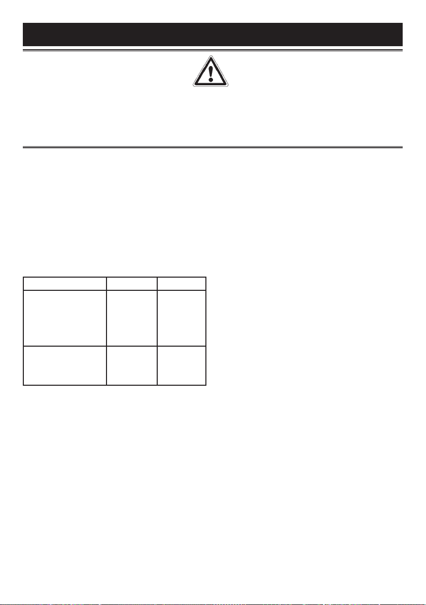
Bruciatori Potenze (W) Ø Pentole
Ausiliario 1000 10 - 14 cm
Semirapido 1750 16 - 18 cm
Rapido 3000 20 - 22 cm
Tripla Corona 3800 22 - 24 cm
Avvertenze
- Controllare sempre che le manopole siano
nella posizione di chiuso (vedi fig.1) quando
l’apparecchiatura non è in funzione.
- In caso di spegnimento accidentale della fiamma,
la valvola di sicurezza, dopo qualche secondo,
interromperà automaticamente l’erogazione del
gas. Per ripristinare il funzionamento riportare la
manopola al punto di accensione (fiamma grande
fig. 1) e premere.
- Durante la cottura con grassi o olii, porre
la massima attenzione in quanto gli stessi,
surriscaldandosi, possono infiammarsi.
- Non utilizzare spray vicino all’apparecchio in
funzione.
- Non devono essere poste sul bruciatore pentole
instabili o deformate per evitare incidenti di
rovesciamento o trabocco.
- Assicurarsi che le maniglie delle pentole siano
posizionate correttamente.
- Quando si accende il bruciatore controllare che
la fiamma sia regolare, abbassare sempre la
fiamma o spegnerla prima di togliere le pentole.
PULIZIA
Prima di ogni operazione scollegare l’apparecchio
dalla rete di alimentazione elettrica. Non utilizzare
pulitori a vapore per la pulizia dell’apparecchio.
Si consiglia di operare ad apparecchio freddo.
Parti smaltate
Le parti smaltate devono essere lavate con una
spugna ed acqua saponata o con detersivo
leggero.
Non usare prodotti abrasivi o corrosivi.
Evitate che sostanze come succo di limone,
pomodoro, acqua salina, aceto, caffè e latte
rimangano a lungo sulle superfici smaltate.
Parti in acciaio inox
L’acciaio inox può rimanere macchiato se lasciato
a contatto per lungo tempo con acqua calcarea o
detergenti aggressivi.
Si consiglia di lavare con acqua saponata e
asciugare con panno morbido.
La lucentezza viene mantenuta mediante l’uso
periodico di prodotti chimici idonei, reperibili in
commercio.
Bruciatori e griglie
Questi pezzi possono essere tolti per facilitare la
pulizia.
I bruciatori devono essere lavati con una spugna
ed acqua saponata o con detersivo leggero,
ben asciugati e rimessi perfettamente nel loro
alloggiamento.
Controllare che i canali spartifiamma non siano
ostruiti.
Verificare che la sonda della valvola di sicurezza
e l’elettrodo di accensione siano sempre ben puliti
per garantire un funzionamento ottimale.
Rubinetti a gas
L’eventuale lubrificazione dei rubinetti deve essere
eseguita esclusivamente da personale
specializzato.
In caso di indurimento o di anomalie di
funzionamento dei rubinetti gas chiamare il
Servizio di Assistenza.

4
ISTRUZIONI PER L’INSTALLATORE
INSTALLAZIONE
Montaggio del piano
L’apparecchio è costruito per essere incassato in
mobili resistenti al calore.
Le pareti dei mobili devono resistere ad una
temperatura di 75°C oltre a quella ambientale
secondo le normative europee.
L’apparecchio è di tipo “ Y “, ovvero può essere
installato con una sola parete laterale a destra o a
sinistra del piano cottura.
Evitare l’installazione dell’apparecchiatura in
prossimità di materiali infiammabili come tendaggi,
canevacci, ecc.
Praticare un’apertura nel piano del mobile delle
dimensioni indicate nella fig. 3 rispettando
una distanza di almeno 50 mm dal bordo
dell’apparecchio alle pareti adiacenti.
MODELLO L (mm) P (mm)
HBS640 / HHS640
HBS660 / HHS660
HBS6G0 / HHS6G0
HBS690 / HHS690
HBS7T0 / HHS7T0
HBS780 / HHS780
560 480
HBS9T0 / HHS9T0
HBS980 / HHS980
HBS9E0 / HHS9E0
HBS9F0 / HHS9F0
820 480
L’eventuale presenza di un pensile al di sopra del
piano cottura deve prevedere una distanza minima dal
top di 760 mm.
Si consiglia di isolare l’apparecchio dal mobile
sottostante con un separatore lasciando uno spazio di
depressione di almeno 10 mm. (fig. 4).
Nel caso di inserimento su base con forno è
necessario prendere opportune precauzioni al fine
di assicurare un’installazione conforme alle norme
antinfortunistiche (CEI-UNI-CIG). Si presti particolare
attenzione a che il cavo elettrico ed il tubo di
alimentazione siano posizionati in modo da non venire
a contatto con le parti calde dell’involucro del forno.
Inoltre, nel caso di installazione sopra un forno senza
ventilazione forzata di raffreddamento, per consentire
un’adeguata aerazione dovranno essere previste
delle opportune prese d’aria con superficie di entrata
inferiore di almeno 200 cm2e superficie di uscita
superiore di almeno 60 cm2.
Fissaggio del piano
Ogni piano di cottura viene corredato di una
speciale guarnizione.
Viene inoltre fornita una serie di ganci da utilizzare
per il fissaggio del piano. A seconda del tipo di
fondo, viene fornito il tipo di gancio di fissaggio
adatto (gancio A o gancio B). Per l’installazione
procedere come segue:
- Togliere dal piano griglie e bruciatori.
- Rovesciare l’apparecchio e stendere lungo il
bordo esterno la guarnizione S (fig. 5).
- Inserire e posizionare il piano cottura nell’apertura
praticata nel mobile e bloccarlo con le viti V dei
ganci di fissaggio G (fig. 6 / 6A).
Locale di installazione
Questo apparecchio non è provvisto di
un dispositivo di scarico dei prodotti della
combustione, è necessario quindi scaricare
questi fumi all’esterno utilizzando una cappa o un
elettroventilatore che entri in funzione ogni volta
che si utilizza l’apparechio.
Il locale dove viene installato l’apparecchio deve
avere un naturale afflusso d’aria per la regolare
combustione del gas e per la ventilazione del
locale; il volume d’aria necessario non deve essere
inferiore a 20 m3.
L’afflusso dell’aria deve avvenire da aperture
permanenti praticate sulle pareti del locale
comunicanti con l’esterno.
La ventilazione può provvenire anche da un
locale attiguo , in questo caso attenersi a quanto
prescritto dalle norme UNI-CIG 7129 e 7131.
Le aperture dovranno avere una sezione minima di
200 cm2.
Collegamento gas
Accertarsi che l’apparecchio sia predisposto
al tipo di gas disponibile, vedi l’etichetta sotto
l’apparecchio. Operare secondo le istruzioni
riportate al paragrafo “trasformazioni gas e
AVVERTENZA IMPORTANTE:
LE OPERAZIONI DI SEGUITO RIPORTATE DEVONO ESSERE ESEGUITE, NEL RISPETTO DELLE
NORME VIGENTI, ESCLUSIVAMENTE DA PERSONALE QUALIFICATO.
LA DITTA COSTRUTTRICE DECLINA OGNI RESPONSABILITÀ PER DANNI A PERSONE ANIMALI O
COSE DERIVANTI DALL’INNOSSERVANZA DI TALI DISPOSIZIONI.

5
ISTRUZIONI PER L’INSTALLATORE
regolazioni“ per l’eventuale adattamento a gas
diversi.
L’apparecchio deve essere collegato all’impianto
gas utilizzando tubi metallici rigidi conformi alla
norma UNI-CIG 7129 o con tubi flessibili in acciaio
a parete continua conformi alla norma UNI-CIG
9891.
Alcuni modelli hanno in dotazione due raccordi:
uno cilindrico A, uno conico B (fig. 7). Scegliere
il raccordo appropriato in base al paese
d’installazione.
Il collegamento non deve provocare sollecitazioni
lla rampa gas.
Ad installazione ultimata controllare la tenuta
dei collegamenti con una soluzione saponosa.
Collegamento elettrico
L’allacciamento alla rete elettrica deve essere
eseguito da personale qualificato e secondo le
norme vigenti.
La tensione dell’impianto elettrico deve
corrispondere a quelle indicata sulla etichetta sotto
l’apparecchio.
Verificare che l’impianto elettrico sia munito di un
efficace collegamento di terra secondo le norme
e le disposizioni di legge. La messa a terra è
obbligatoria.
Se l’apparecchio è sprovvisto di spina, applicare al
cavo di alimentazione una spina normalizzata.
Per il collegamento diretto alla rete, è
necessario prevedere un dispositivo che
assicuri la disconnessione dalla rete, con una
distanza di apertura dei contatti che consenta la
disconnessione completa nelle condizioni della
categoria di sovratensione III, conformemente alle
regole di installazione.
TRASFORMAZIONI GAS E REGOLAZIONI
Sostituzione ugelli
Se l’apparecchiatura risulta predisposta per
un diverso tipo di gas di quello disponibile è
necessario sostituire gli ugelli dei bruciatori.
La scelta degli ugelli da sostituire deve essere
fatta secondo la tabella “caratteristiche tecniche”
riportata di seguito.
Procedere quindi come segue:
- Togliere le griglie e i bruciatori.
- Con una chiave diritta L svitare l’ugello U (fig. 8)
e sostituirlo con quello corrispondente.
- Bloccare energicamente l’ugello.
Regolazione bruciatori
La regolazione del minimo deve essere sempre
corretta e la fiamma deve rimanere accesa anche
con un brusco passaggio dalla posizione di
massimo a quella di minimo.
Se questo non avviene è necessario regolare il
minimo come segue:
- Accendere il bruciatore;
- Ruotare il rubinetto fino alla posizione di minimo
(fiamma piccola);
- Sfilare la manopola dall’asta del rubinetto;
- Introdurre un cacciavite a taglio C nel foro F del
rubinetto (fig. 9-9A) e ruotare la vite by-pass fino
ad una corretta regolazione del minimo.
Per bruciatori funzionanti a gas G 30 la vite by-
pass deve essere avvitata completamente.
MANUTENZIONE
Sostituzione cavo alimentazione
In caso di sostituzione del cavo di alimentazione si
dovrà utilizzare un cavo a norme del tipo H05VV-F
o H05RR-F di sezione 3 x 0,75 mm2.
Il collegamento alla morsettiera va eseguito come
illustrato in fig. 10 e 10A:
cavetto L marrone (fase)
cavetto N blu (neutro)
cavetto verde-giallo (terra)

6
Dear Customer,
We thank you and congratulate you on granting us your preference, by purchasing one of our products.
We are sure that this new appliance, manufactured with quality materials, will meet your requirements in
the best possible way.
The use of this new equipment is easy. However, we invite you to read this booklet carefully, before
installing and using the appliance.
This booklet gives the right information on the installation, use and maintenance, as well as useful advice.
THE MANUFACTURER
GENERAL NOTICE
We invite you to read this instruction booklet carefully, before installing and using the equipment.
It is very important that you keep this booklet together with the equipment for any future
consultation.
If this equipment should be sold or transferred to another person, make sure that the new
user receives the booklet, so that he can learn how to operate the appliance and read the
corresponding notice.
This is a Class 3 appliance.
WARNING:
- The installation must be carried out by experienced and qualified personnel, in conformity with the
regulations in force.
- This appliance is not intended for use by person (including children) with reduced physical, sensory or
mental capabilities, or lack of experience and knowledge, unless they have been given supervision or
instruction cencerning use of the appliance by a person responsible for their safety.
- Children should be supervised to ensure that they do not play with the appliance.
- While the appliance is running, watch the children and make sure they neither stay near the equipment,
nor touch the surfaces that have not cooled down completely.
- Before powering the equipment, check that it is properly adjusted for the type of gas at disposal (see the
“installation” paragraph).
- Before carrying out the maintenance or cleaning the equipment, cut power supply off and make it cool
down.
- Make sure that air circulates around the gas equipment. Insufficient ventilation produces a lack of oxygen.
- In case of an intense or prolonged use of the equipment, it may be necessary to improve aeration, for
example by opening a window or increasing the mechanical suction power, if it exists.
- The products of combustion must be discharged outside through a suction hood or an electric fan (see the
“installation” paragraph).
- For any possible operation or modification, apply to an authorised Caple Service Centre and demand
original spare parts.
The product label, with the serial number, is sticked under the hob.
The manufacturer refuses all responsibility for possible damages to things or people, resulting
from a wrong installation or from an improper, incorrect or unreasonable use of this equipment.
Declaration of conformity:
We hereby declare that our products satisfy the applicable European
directives, orders and regulations, as well as the requirements stated in
the referenced standards.

7
INSTRUCTIONS FOR THE USER
It is necessary that all the operations regarding the installation, adjustment and
adaptation to the type of gas available are carried out by qualified personnel, in
conformity with the regulations in force.
The specific instructions are described in the booklet section intended for the
installer.
USING THE BURNERS
The symbols silk-screen printed on the side of the
knob indicate the correspondence between the
knob and the burner.
Start-up without valves
Turn the corresponding knob anticlockwise up
to the maximum position (large flame, fig. 1) and
press startup button P (fig. 1).
Automatic start-up with valves
Turn the corresponding knob anticlockwise up
to the maximum position (large flame, fig.1) and
press the knob.
Once the burner has been started up, keep the
knob pressed for about 6 seconds.
Using the burners
In order to obtain the maximum yield without waste
of gas, it is important that the diameter of the pot is
suitable for the burner potential (see the following
table), so as to avoid that the flame goes out of the
pot bottom (fig. 2).
Use the maximum capacity to quickly make the
liquids reach the boiling temperature, and the
reduced capacity to heat food or maintain boiling.
All of the operating positions must be chosen
between the maximum and the minimum ones,
never between the minimum position and the
closing point.
The gas supply can be interrupted by turning the
knob lockwise up to the closing position.
If there is no power supply, it is possible to light the
burners with matches, setting the knob to the start-
up point (large flame, fig.1).
Burners Power (W) Ø of pots
Auxiliary 1000 10 - 14 cm
Semi-rapid 1750 16 - 18 cm
Rapid 3000 20 - 22 cm
Triple ring 3800 22 - 24 cm
Notice
- When the equipment is not working, always
check that the knobs are in the closing position
(see fig.1).
- If the flame should blow out accidentally, the
safety valve will automatically stop the gas
supply, after a few seconds. To restore operation,
set the knob to the lighting point (large flame, fig.
1) and press.
- While cooking with fat or oil, pay the utmost
attention as these substances can catch fire
when overheated.
- Do not use sprays near the appliance in
operation.
- Do not place unstable or deformed pots on the
burner, so as to prevent them from overturning or
overflowing.
- Make sure that pot handles are placed properly.
- When the burner is started up, check that the
flame is regular and, before taking pots away,
always lower the flame or put it out.
CLEANING
Before any operation, disconnect the appliance
from the electric grid. Don’t use a steam cleaner
for the cleaning the hob.
It is advisable to clean the appliance when it is cold.
Enamelled parts
The enamelled parts must be washed with a
sponge and soapy water or with a light detergent.
Do not use abrasive or corrosive products.
Do not leave substances, such as lemon or tomato
juice, salt water, vinegar, coffee and milk on the
enamelled surfaces for a long time.
Stainless steel parts
Stainless steel can be stained if it remains in
contact with highly calcareous water or aggressive
detergents for an extended period of time.
The stainless steel parts should also be cleaned
with soapy water and then dried with a soft cloth.
Burners and racks
These parts can be removed to make cleaning
easier.
The burners must be washed with a sponge and
soapy water or with a light detergent, wiped well
and placed in their housing perfectly. Make sure
that the flame-dividing ducts are not clogged.
Check that the feeler of the safety valve and the
startup electrode are always perfectly cleaned, so
as to ensure an optimum operation.
Gas taps
The possible lubrication of the taps must be carried
out by specialized personnel, exclusively.
In case of hardening or malfunctions in the gas
taps, apply to the Customer Service.

8
INSTRUCTIONS FOR THE INSTALLER
IMPORTANT NOTICE:
THE OPERATIONS INDICATED BELOW MUST BE FOLLOWED BY QUALIFIED PERSONNEL
EXCLUSIVELY, IN CONFORMITY WITH THE REGULATIONS IN FORCE.
THE MANUFACTURING FIRM REFUSES ALL RESPONSIBILITY FOR DAMAGES TO PEOPLE,
ANIMALS OR THINGS, RESULTING FROM THE FAILURE TO COMPLY WITH SUCH PROVISIONS.
INSTALLATION
Installing the top
The appliance is design-ed to be embedded into
heat-resistant pieces of furniture.
The walls of the pieces of furniture must resist a
temperature of 75°C besides the room one.
The equipment must not be installed near inflammable
materials, such as curtains, cloths, etc.
Make a hole in the top of the piece of furniture, with
the dimensions indicated in fig. 3, at a distance of at
least 50 mm from the appliance border to the adjacent
walls.
MODEL L (mm) P (mm)
HBS640 / HHS640
HBS660 / HHS660
HBS6G0 / HHS6G0
HBS690 / HHS690
HBS7T0 / HHS7T0
HBS780 / HHS780
560 480
HBS9T0 / HHS9T0
HBS980 / HHS980
HBS9E0 / HHS9E0
HBS9F0 / HHS9F0
820 480
Any possible wall unit over the cook-top must be placed
at a distance of at least 760 mm from the top.
It is advisable to isolate the appliance from the piece of
furniture below with a separator, leaving a depression
space of at least 10 mm (g. 4).
If the hob is going to be installed on the top of an oven,
precautions must be taken to guarantee an installation
in accordance with current accident prevention
standards. Pay particular attention to the position of the
electric cable and gas pipe: they must not touch any hot
parts of the oven.
Moreover, if the hob is going to be installed on the top
of a built in oven without forced cooling ventilation,
proper air vents must be installed to guarantee an
adequate ventilation, with the lower air entering with a
cross section of at least 200 cm2, and the higher air
exiting with a cross section of at least 60 cm2.
Fastening the top
Every cook-top is equipped with a special washer. A set
of hooks is also supplied for mounting the cook-top.
Depending on the type of mounting surface, the suitable
type of mounting hook is supplied (hook A or hook B).
For the installation proceed as follows:
- Remove the racks and burners from the top.
- Turn the appliance upside down and lay the
washer S along the external border (fig. 5).
- Introduce and place the cook-top in the hole
made in the piece of furniture, then block it with
the V screws of the fastening hooks G (fig. 6/6A).
Installation room
This appliance is not provided with a device for
exhausting the products of combustion. Therefore,
it is necessary to discharge these smokes outside.
The room where this appliance is installed must have
a natural air inflow, so as to ensure a regular gas
combustion and room ventilation: the necessary air
volume must not be lower than 20 m3.
Air must come from permanent openings made on
the room walls that communicate with the outside.
The section of these openings shall correspond to at
least 200 cm2.
Gas connection
Make sure that the appliance is adjusted for the gas
type available (see the label under the appliance).
Follow the instructions indicated in the chapter “gas
transformations and adjustments” for the possible
adaptation to different gases.
The appliance must be connected to the gas system by
means of still metal pipes or exible steel pipes having
continuous walls, in compliance with the regulations in
force.
Some models are equipped with both cylindrical A and
conical B connectors for gas supply (g. 7).
Please select the type which is correct for the supply
concerned.
The connection must not stress the gas ramp.
Once the installation is over, check the connection
seal with a soapy solution.

9
INSTRUCTIONS FOR THE INSTALLER
Electric connection
The connection to the electric grid must be carried
out by qualified personnel and in conformity with
the regulations in force.
The voltage of the electric system must correspond
to the value indicated in the label under the
appliance. Make sure that the electric system is
provided with an effective ground connection in
compliance with the regulations and provisions of
the law. Grounding is compulsory.
GAS TRANSFORMATIONS AND
ADJUSTMENTS
Replacing the nozzles
If the equipment is adjusted for a type of gas that is
different from the one available, it is necessary to
replace the burner nozzles.
The choice of the nozzles to replace must be
made according to the table of the “technical
characteristics” as enclosed.
Act as follows:
- Remove the racks and burners.
- by means of a straight spanner L, unscrew
the nozzle U (fig. 8) and substitute it with the
corresponding one.
- tighten the nozzle strongly.
Adjusting the burners
The lowest flame point must always be properly
adjusted and the flame must remain on even if
there is an abrupt shift from the maximum to the
minimum position.
If this is not so, it is necessary to adjust the lowest
flame point as follows:
- start the burner up;
- turn the tap up to the minimum position (small
flame);
- remove the knob from the tap rod;
- introduce a flat-tip screwdriver C in the hole F of
the tap (fig. 9-9A) and turn the by-pass screw up
to a proper adjustment of the lowest flame point.;
As regards propane gas burners, the by-pass
screw must be tightened completely.
MAINTENANCE
Replacing the power supply cable
If the power supply cable should be replaced, it is
necessary to use a cable with a section of 3 x 0.75
mm2, type H05VV-F or H05RR-F, complying with
the regulations in force.
The connection to the terminal board must be
effected as shown in fig. 10 and 10A:
brown cable L (phase)
blue cable N (neutral)
green-yellow cable (ground)

10
1 2
3 4
5 6A 6
87
910 10/A
CHIUSO
CLOSED
MASSIMO
MAXIMUM
MINIMO
MINIMUM
F
9A
F

11
1 Bruciatore rapido di 3000 W
2 Bruciatore semirapido di 1750 W
3 Bruciatore ausiliario di 1000 W
4 Bruciatore tripla corona di 3800 W
8 Manopola comando bruciatore
1 Rapid burner 3000 W
2 Semi-rapid burner 1750 W
3 Auxiliary burner 1000 W
4 Triple ring burner 3800 W
8 Control knob for burner
ARTES ECOS
HHS640 - HHS660 (EE gas hob = 56.9 %) HBS640 - HBS660 (EE gas hob = 56.9 %)
HHS6G0 - HHS690 (EE gas hob = 57.4 %) HBS6G0 - HBS690 (EE gas hob = 57.4 %)
HHS7T0 - HHS780 (EE gas hob = 57.2 %) HBS7T0 - HBS780 (EE gas hob = 57.2 %)
HHS9E0 - HHS9F0 (EE gas hob = 57.2 %) HBS9E0 - HBS9F0 (EE gas hob = 57.2 %)
HHS9T0 - HHS980 (EE gas hob = 57.2 %) HBS9T0 - HBS980 - HMS9T0 (EE gas hob = 57.2 %)

12
TABELLA CARATTERISTICHE TECNICHE
TECHNICAL CHARACTERISTIC TABLES
BRUCIATORI
BURNERS GAS
PRESSIONE
ESERCIZIO
NORMAL
PRESSURE
PORTATA
TERMICA
NOMINAL
RATE
DIAMETRO
UGELLO
INJECTOR
DIAMETER
DIAMETRO
BY PASS
RUBINETTO
TYPE BY
PASS
DIAMETER
PORTATA
TERMICA (W)
NOMINAL HEAT
INPUT (W)
(EE gas hob )
N° DENOMINAZIONE
DESCRIPTION mbar g/h L/h 1/100 mm 1/100 mm Max. Min. (%) *
1RAPIDO
RAPID
G30 28 - 30 225 - 85 42 3000 950
56.7G31 37 214 - 85 42 3000 950
G20 20 - 290 115Y Reg. 3000 950
2SEMIRAPIDO
SEMI-RAPID
G30 28 - 30 126 - 65 31 1750 600
57G31 37 125 - 65 31 1750 600
G20 20 - 165 97Z Reg. 1750 600
3AUSILIARIO
AUXILIARY
G30 28 - 30 71 - 50 27 1000 450
/G31 37 71 - 50 27 1000 450
G20 20 - 99 72X Reg. 1000 450
4TRIPLA CORONA
TRIPLE RING
G30 28 - 30 278 - 98 60 3800 2100
58.1G31 37 272 - 98 60 3800 2100
G20 20 - 367 135K Reg. 3800 2100
Titolo breve o riferimento ai metodi di misurazione e di calcolo utilizzati per stabilire la conformità
con i requisiti di cui sopra.
La performance di ogni singolo bruciatore viene calcolata secondo la norma EN 30-2-1 + A1: 2003 + A2:
2005.
Il rendimento totale del piano di cottura è calcolato in base al regolamento UE 66/2014 Par. 2.2.
L’efcienza viene calcolata solo per i bruciatori con una capacità nominale superiore 1,16 KW (EN 30-2-1
+ A1: 2003 + A2:. 2005; Par 4.1)
Informazioni rilevanti per il cliente per minimizzare il consumo di energia durante l’uso.
Consigli per risparmiare:
utilizzare pentole comuni con base piana,
utilizzare pentole con il formato corretto,
utilizzare pentole con il coperchio,
ridurre al minimo la quantità di grasso liquido o, quando si avvia un liquido bollente ridurre l’impostazione.
Short title or reference to the measurement and calculation methods used to establish compli-
ance with the above requirements.
The performance of each individual burner is calculated according to standard EN 30-2-1 + A1:2003 +
A2:2005
The total efciency of the hob is calculated according to the EU Regulation 66/2014 Par. 2.2
The efciency is calculated only for the burners with a nominal capacity exceeding 1,16 KW ( EN 30-2-1
+ A1:2003 + A2:2005; Par. 4.1)
Information which is relevant to the customer to minimize the energy consumption during usage:
Energy Saving Tips: use pots having at base, Use pots with proper size, use pots with lid, minimize the
amount of liquid or fat, when liquid starts boiling reduce the setting.

13

14

15

16
This product complies with EU Directive 2002/96/EC.
The crossed-out dustbin symbol reported on the appliance indicates that the appliance must be disposed
of separately from other domestic refuse at the end of its useful life. It must therefore be delivered to a
waste recycling centre specically for electric and electronic equipment or returned to the retailer at the
moment of purchase of a new equivalent appliance.
The user is responsible for delivering the appliance to the appropriate collection centre at the end of its useful life, Failure
to do so may result in a ne, as provided for by laws governing waste disposal.
Differential collection of waste products for eventual recycling, treatment and environmentally friendly disposal helps
reduce possible negative effects on the environment and health, and also enables the materials making up the product
to be recycled.
For more detailed information on the available refuse collection systems, refer to the local Municipal Solid Waste disposal
centre or the shop where the product was purchased.
Producers and importers are responsible for fullling their obligations as regards recycling, treatment and environmentally
friendly disposal by directly or indirectly participating in the collection system.
Questo prodotto è conforme alla Direttiva EU 2002/96/EC.
Il simbolo del cestino barrato riportato sul prodotto indica che i Riuti derivanti dalle Apparecchiature
Elettriche ed Elettroniche (RAEE) non devono essere buttati nella spazzatura indifferenziata (cioè insieme
ai “riuti urbani misti”), ma devono essere gestiti separatamente così da essere sottoposti ad apposite
operazioni per il loro riutilizzo, oppure a uno specico trattamento, per rimuovere e smaltire in modo sicuro
le eventuali sostanze dannose per l’ambiente ed estrarre le materie prime che possono essere riciclate.
In Italia i RAEE devono perciò essere consegnati ai Centri di Raccolta (chiamati anche isole ecologiche o piattaforme
ecologiche) allestiti dai Comuni o dalle Società di igiene urbana. Quando si acquista una nuova apparecchiatura, inoltre,
si può consegnare il RAEE al negoziante, che è tenuto a ritirarlo gratuitamente (ritiro “uno contro uno”); i RAEE di
“piccolissime dimensioni” (nei quali cioè nessuna dimensione supera i 25 cm) possono essere consegnati gratuitamente
ai negozianti anche quando non si compra nulla (ritiro “uno contro zero” – che però è obbligatorio solo per i negozi con
supercie di vendita superiore a 400 mq).
This manual suits for next models
19
Table of contents
Languages:
Popular Cooktop manuals by other brands

Lacor
Lacor 69132 Instructions for use and maintenance

Frigidaire
Frigidaire FGC6X9XGTA Wiring diagram

KitchenAid
KitchenAid KECC607BBL01 quick guide

Miele
Miele KM 611 Series Operating and installation instructions

KitchenAid
KitchenAid KECD806RSS04 parts list

Frigidaire
Frigidaire FGC30S4A Factory parts catalog

GE
GE Monogram ZEU30R installation instructions

Bosch
Bosch AutoChef NETP666SUC Quick reference guide

Electrolux
Electrolux E30IC75FSS - 30 Inch Drop-In Induction... installation instructions

Whirlpool
Whirlpool GJC3055RS - Smoothtop Electric Cooktop Use & care guide

Omega
Omega OC63TXA Installation and operating instructions

GE
GE PP932BMBB features and benefits