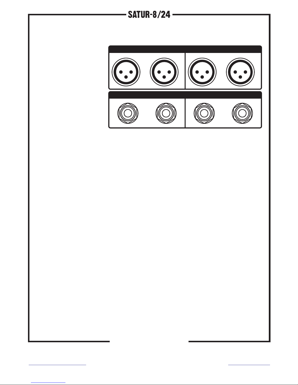
MAIN and MONITOR outputs are balanced XLR.
INSERT inputs and outputs are balanced Jack TRS.
LOOPTROTTER
AUDIO ENGINEERING
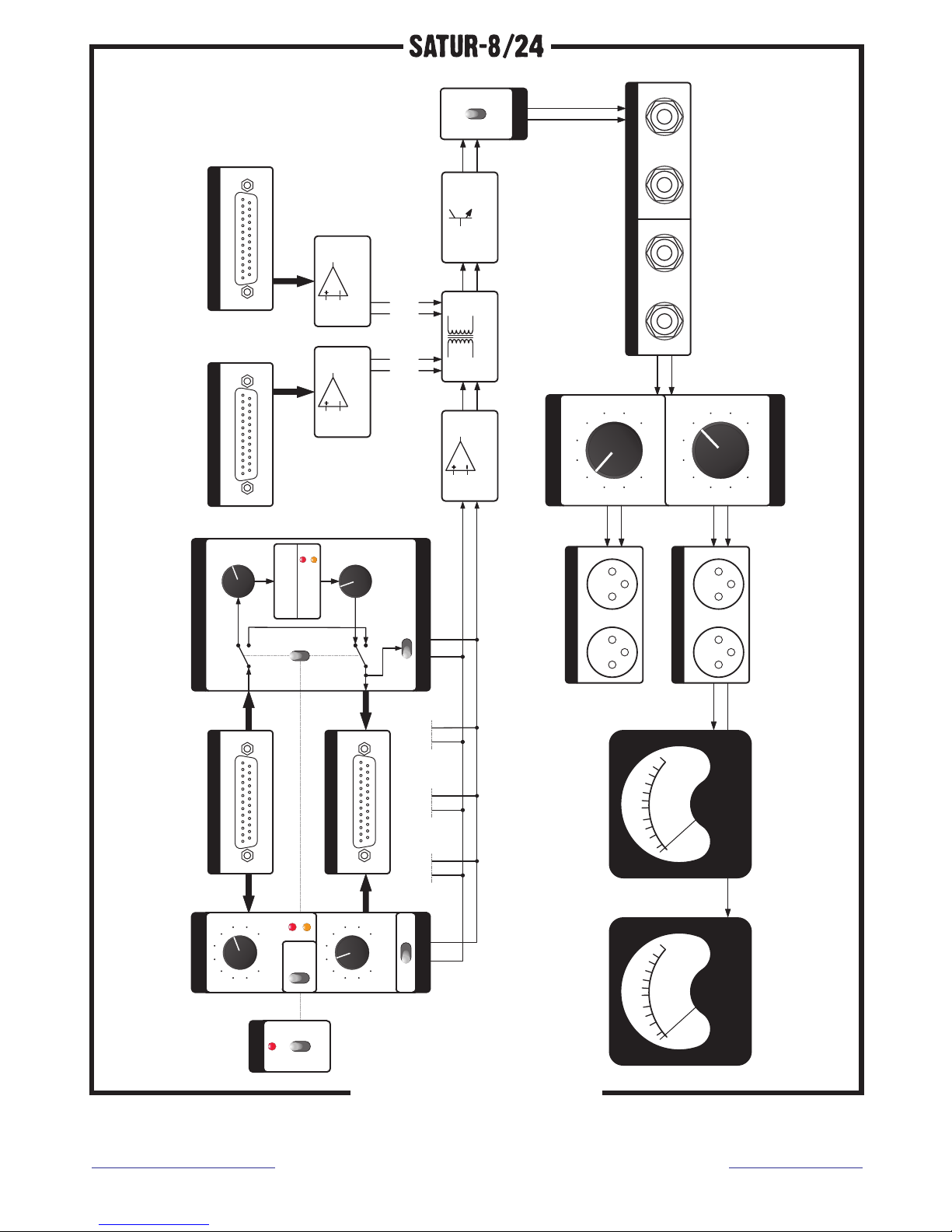
Signal path
SATUR-8/24 has 24 input channels. Signal incoming to channels 1-8
flows directly on 8 saturation circuits. Signal incoming to channels
9-24 inputs directly the summing bus. Channels with odd numbers (9-
23) are assigned to the left channel. Channels with even numbers
(10-24) are assigned to the right channel.
Within the saturation circuits (channels 1-8) the incoming signal enters
the DRIVE potentiometer, next it flows through the preemphasis module,
which decreases the low frequencies level. Following, the signal goes
to the saturation circuit. The saturation level – the amount of added
harmonics – depends directly on the input level, controlled with the
DRIVE knob. After the saturation circuit there is deemphasis module,
which boosts low frequencies, next the processed signal goes through
OUTPUT potentiometer. Having gone through the OUTPUT knob the signal is
split and directed to outputs 1-8 and LCR switches, which allow to pan the
signal.
The signals from channels 1-8, 9-16 and 17-24 are being summed
independently by operational amplifiers (active summing) and then they
go to summing transformers (passive summing). Following the transformers
the signal is amplified with 30dB by transistor amplifiers. Totally
summed signal split into left and right channel flows through the “magic”
circuit. This circuit can be engaged with a switch on the front panel.
There is an option to insert an external device, such as equalizer or
compressor, on the summing bus, via the INSERT connectors on the rear
panel. After the INSERT connectors the signal is split and goes to
potentiometers controlling the MAIN and MONITOR output levels. Two VU
meters on the front panel indicate the signal MAIN OUTPUT levels of the
left and right channel.
XLR:
PIN 1: ground
PIN 2: positive
PIN 3: negative
TRS:
Tip : Hot(+)
Ring : Cold(-) Sleeve
: GND
INPU T
OUTP UT I N SE R T
R RL L
MONI TOR
MAIN OU TPUT
R RL L
1
3
2 1
3
2 1
3
2 1
3
2
Contact:
www.looptrotter.com.pl
Distribution:
www.mjadiolab.pl