'RF,,*%BGRF[ S
pagina del display (moduli espansione), dove si vedono il numero, il tipo
e lo stato dei moduli collegati.
xLa numerazione degli I/O viene elencata sotto ogni modulo.
xLo stato (attivato/disattivato) degli I/O e dei canali di comunicazione
viene evidenziato con la scritta in negativo.
display (expansion modules), where it is possible to see the number, the
type and the status of the modules.
xThe I/O numbering is shown under each module.
xThe I/O status (active/not active) and communication channel status is
highlighted with a reverse code.
Risorse aggiuntive
xI moduli di espansione forniscono delle risorse aggiuntive che possono
essere sfruttate tramite gli opportuni menu di impostazione.
xI menu di impostazione che riguardano le espansioni sono disponibili
anche se i moduli non sono fisicamente presenti.
xDato che è possibile aggiungere più moduli della stessa tipologia (ad
esempio due interfacce di comunicazione) i relativi menu di
impostazione sono multipli, identificati da un numero progressivo.
xDi seguito una tabella che indica quanti moduli di ogni tipo possono
essere montati contemporaneamente e in quali slot possono esere
montati. Il numero totale di moduli deve essere <= 2.
TIPO MODULO CODICE FUNZIONE Nr. MAX REV
COMUNICAZIONE EXP 10 10 USB 2 0
EXP 10 11 RS-232 2 0
EXP 10 12 RS-485 2 0
EXP 10 13 Ethernet 1 0
EXP 10 14 Profibus® DP 1 1
I/O DIGITALI EXP 10 00 4 INGRESSI 2 0
EXP 10 01 4 USCITE
STATICHE 2 0
EXP 10 02 2 INGRESSI +
2 USCITE ST. 2 0
EXP 10 03 2 RELE’ IN
SCAMBIO 2 0
EXP 10 06 2 RELE’ NA 2 0
EXP 10 07 3 RELE’ NA 2 0
EXP 10 08 2 INGRESSI +
2 RELE’ NA 2 0
Additional resources
xThe expansion modules provide additional resources that can be used
through the dedicated setup menus.
xThe setup menus related to the expansions are always accessible, even
if the expansion modules are not physically fitted.
xSince it is possible to add more than one module of the same typology
(for instance two communication interfaces), the setup menus are
multiple, identified by a sequential number.
xThe following table indicates how many modules of each group can be
mounted at the same time. The total number of modules must be less or
equal than 2.
MODULE TYPE CODE FUNCTION MAX Nr. REV
COMMUNICATION EXP 10 10 USB 2 0
EXP 10 11 RS-232 2 0
EXP 10 12 RS-485 2 0
EXP 10 13 Ethernet 1 0
EXP 10 14 Profibus® DP 1 1
DIGITAL I/O EXP 10 00 4 INPUTS 2 0
EXP 10 01 4 STATIC
OUTPUTS 2 0
EXP 10 02 2 INPUTS +
2 ST. OUTPUTS 2 0
EXP 10 03 2 CHANGEOVER
RELAYS 2 0
EXP 10 06 2 RELAYS NO 2 0
EXP 10 07 3 RELAYS NO 2 0
EXP 10 08 2 INPUTS +
2 RELAYS NO 2 0
Canali di comunicazione
xAll’ATL610 è possibile connettere un massimo di 2 moduli di
comunicazione, denominati COMn. Il menu d impostazione
comunicazioni prevede quindi due sezioni (n=1 ... 2) di parametri per
l’impostazione delle porte di comunicazione.
xI canali di comunicazione sono completamente indipendenti, sia dal
punto di vista hardware (tipo di interfaccia fisica) che dal punto di vista
del protocollo di comunicazione.
xI canali di comunicazione possono funzionare contemporaneamente.
xAttivando la funzione Gateway, è possibile avere un ATL610
equipaggiato con una porta Ethernet ed una porta RS485, che fa da
‘ponte’ verso altri dispositivi dotati della sola porta RS485, in modo da
ottenere un risparmio (1 solo punto di accesso Ethernet).
xIn questa rete, l’ATL610 dotato di porta ethernet avrà il parametro della
funzione Gateway impostato su ON per entrambi i canali di
comunicazione (COM1, COM2) mentre gli altri dispositivi saranno
configurati normalmente con Gateway = OFF.
Communication channels
xThe ATL610 supports a maximum of 2 communication modules,
indicated as COMn. The communication setup menu is thus divided into
two sections (n=1 … 2) of parameters for the setting of the ports.
xThe communication channels are completely independent, both for the
hardware (physical interface) and for the communication protocol.
xThe two channels can communicate at the same time.
xActivating the Gateway function it is possible to use an ATL610 with both
an Ethernet port and a RS485 port, that acts as a bridge over other
devices equipped with RS-485 only, in order to achieve a more
economic configuration (only one Ethernet port).
xIn this network, the ATL610 with Ethernet port will be set with both
communication channels (two among COM1, COM2) with Gateway
function set to ON, while the other devices will be configured normally
with Gateway = OFF.
Ingressi, uscite, variabili interne, contatori
xGli ingressi e le uscite sono identificati da una sigla e da un numero
progressivo. Ad esempio gli ingressi digitali sono denominati INPx, dove
x rappresenta il numero dell’ingresso. Allo stesso modo, le uscite digitali
sono denominate OUTx.
COD DESCRIZIONE BASE EXP (ATL610)
INPx Ingressi digitali 1…6 7…14
OUTx Uscite digitali 1…7 8…15
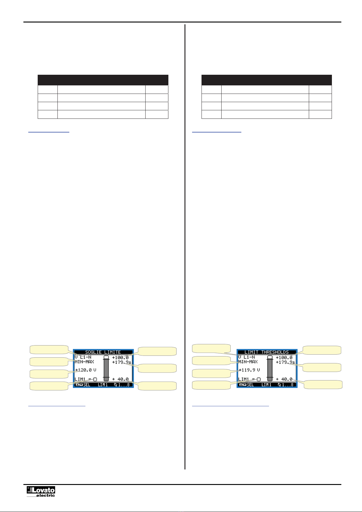
xAllo stesso modo degli ingressi/uscite, esistono delle variabili interne
(bit) che possono essere associate alle uscite o combinate fra loro. Ad
esempio si possono applicare delle soglie limite alle misure effettuate
dal sistema. In questo caso la variabile interna, denominata LIMx, sarà
attivata quando la misura risulta essere fuori dai limiti definiti dall’utente
tramite il relativo menu di impostazione.
xInoltre sono disponibili fino a 4 contatori (CNT1…CNT4) che possono
Inputs, outputs, internal variables, counters
The inputs and outputs are identified by a code and a sequence number.
For instance, the digital inputs are identified by code INPx, where x is the
number of the input. In the same way, digital outputs are identified by code
OUTx.
COD DESCRIPTION BASE EXP (ATL610)
INPx Digital Inputs 1…6 7…14
OUTx Digital Outputs 1…7 8…15
xIn a similar way, there are some internal bit-variables (markers) that can
be associated to the outputs or combined between them. For instance, it
is possible to apply some limit thresholds to the measurements done by
the system. In this case, an internal variable named LIMx will be
activated when the measurements will go outside the limits defined by
the user through the dedicated setting menu.
xFurthermore, there are up to 4 counters (CNT1..CNT4) that can count
pulses coming from an external source (through a digital input INPx) or