LTH Škofja Loka ZS Series Owner's manual

TECHNICAL INSTRUCTIONS FOR
USAGE OF DEEPFREEZERS ZS
TECHNISCHE BETRIEBSANLEITUNG
FÜR DIE GEFRIERTRUHE ZS
INSTRUCTIONS TECHNIQUES POUR
EMPLOI DES CONGÉLATEURS ZS
12975.27 lV / 2004

3

4
1. DESCRIPTION OF THE FREEZER
The freezer consists of a casing with a cover and a cooling system with automation. It is made heat-
resistant by polyurethan insulation. The inner layer is made from galvanized sheet metal, corrosion
resistant, and is protected in the same way as the other visible surfaces by high quality lacquer-
plastification. A light can be built in to the cover (2) for the lightening of the freezer’s interior and a
lock can be built in to the grip (1). Effective cooling is guaranteed by a hermetically-closed cooling
system with an evaporator which is in direct contact with the inner layer of the freezer. The device
functions completely automatically by means of a thermostat which regulates the required
temperature.
2. INSTALLATION OF THE FREEZER
The freezer should be installed in a cool, dry room and should not be exposed to direct sunlight. In
should stand on an even surface, horizontal and about 15 cm away from any walls. For an
economical electricity consumption it is recommended that the freezer be installed in a room with a
constant temperature throughout the year. Do not open the freezer unnecessarily check the
temperature in the freezer, which should vary from -18 °C to -20 °C. It should be installed in a place
with adequate air circulation, which is especially important for freezers with a static condenser (8), as
they have no ventilator. For transport purposes this freezer has a styropor insert (7) between the wall
of the freezer and the condenser, which should be removed before connecting the freezer. The two
boards (11), placed between the cover and the basin of the freezer in order to protect the sealing
profile from damage during transportation, should be removed from every freezer.
3. CONNECTION OF THE FREEZER TO THE MAINS
!
If the plug or the cable cord is damaged, replace the complete cord or the plug and use
original spare part supplied by the manufacturer or authorised service centre.
The freezer should be connected to a 230 V, 50 Hz mains, directy from the plug into the socket; it
should be earthed in conformance with the regulations. The device is sensitive to oscillation of
electrial tension. The tolerance amounts to ±10%from the nominal tension. It is recommended that,
in case of larger deviations, the freezer should be connected to the mains via a tension corrector, by
which undisturbed fonctioning is guaranteed.
The wall socket, into which the plug is connected, shall be on such location as to provide free access.
4. SIGNAL DEVICE
The lower right part of the outer layer has an armature panel (6) with switches, lights and a
thermostat button, which inform the user about the functioning of the freezer.
A - Yellow switch with imprinted snowflake. By pressing it, the yellow lamp lights up and the
freezer functions uninterruptedly, independently from the temperature in the freezer. By
pressing the switch for the second time, the forced functioning is switched off and automatic
functioning is switched on, which is regulated by the thermostat.
B - The green light with the imprinted mark for tension signalizes the presence of tension - the
green light is on continuously.
C - Red light with imprinted alarm mark. If the temperature in the freezer is too high, the red lamp
lights up and the sound device is released. The alarm can be switched off by pressing the

5
switch, at which the red lamp is still on. When the light goes off, the knob is switched again, so
that in case of a temperature increase in the freezer, above the allowed level, a warning is again
give by the alarm. The red lamp with impressed alarm mark lights up, when the temperature in
the freezer is too high. It is on as long as the temperature does not fall to the tolerated range.
D - Thermostat button - with a coin we can adjust the temperature in the freezer. During the
production process, the thermostat is adjusted to the most appropriate temperature, therefore,
under normal conditions of operation, readjustment is not necessary, if a different temperature
in the freezer is required, this can be attained by turning the termostat button clockwise for
lower temperatures and anticlockwise for higher temperatures in the freezer.
5. FILLING OF THE FREEZER
Before the first filling it is recommended to check the functioning of the freezer. Connect the freezer
to the mains and press switch ”A” (the yellow light is on).
The interior of the empty freezer has to cool off to the prescribed temperature in approximately two
hours. Then the switch is adjusted to automatic functioning by pressing switch ”A” (the light is not
on) - thermostat (9) regulates the temperature in the freezer. Having checked the correct functioning
of the freezer, it can be filled with the first quantity of food. Switch ”A” has to be in the position of
uninterrupted functioning of the freezer (the yellow light is on). Take care not to fill the whole
freezer at once, but only the daily capacity, which is written on plate (10) at the rear of the freezer.
Freshly packaged food should be piled up against the outer wall, so that it freezer faster. When the
freezer has been filled, the yellow light should be on at least one more day, then switch over to
automatic functioning.
6. STOPPING THE FREEZER
The functioning of the freezer is stopped simply by pulling the plug out of the socked.
7. DEWING OF THE FREEZER
Dewing of the freezer is usually due to a high humidity of the room in which the freezer has been
installed. The moisture which is present in the air condenses on the coolest object, that is the freezer,
due to which the surface dews and water appears under it.
In this case it is recommended to move the freezer to another, dry room and install it in such a way
that the best possible air circulation around it is provided.
Move the freezer away from the walls and place something under it.
8. REPLACEMENT OF LIGHTBULB (if built in)
When the lightbulb burns out, it should be changed. First the freezer is disconnected and then the
bulb protector is pressed lengthwise. In this way the protector can be removed from the cover. The
new bulb must have an E14 coil and 10 W power.
9. CLEANING OF THE CONDENSER

6
The condenser is cleaned once or twice annually. After having disconected the freezer, the condenser
is cleaned with a soft brush or vacuum cleaner. While cleaning the dynamic condenser (with
ventilator) the screen of the aggregate compartment which prevents access to the cooling aggregate,
should be removed previously, where as at the cleaning of a static condenser this is not necessary.
This is because the latter has been mounted to the rear of the freezer.
10. DEFROSTING AND CLEANING
After some time, crusted snow collects on the inner layer, which has to be removed at least twice
annually. The freezer is disconnected, the cover is opened and the food is placed into baskets (3), put
in a cold room and wrapped in several layers of newspaper, a blanked or other appropriate insulation
material. With the scraper, which comes supplied with the freezer, remove the crusted snow from the
interior walls. After defrosting, the freezer is cleaned with lukewarm water with a mild detergent.
Then it is dried with a soft cloth and left open for sufficient time, to let it dry well. The defrosting
process can be accelerated by placing a container with boiling water in the freezer, after having
removed the crushed snow, and closing the freezer for some minutes (until all the crushed snow falls
down).
Clean the freezer than, when it contains little food.
11. BREAKDOWNS
It is recommended that you check the freezer regularly.
The control lights on the armature plate inform the user about the correct functioning of the freezer.
a) If no lights are on, it is likely that the electric current has been interupted. Check the fuse and the
socked.
b) If the socket is under tension and the signal lamps are not on, you should call the nearest service.
Again service should be called when the red light is on, except in the cases which have been
mentioned in these instructions and when the freezer is functioning normally.
c) Do not open the freezer in case of power failure or breakdown, in order to preserve the low
temperature longer (24 - 30 hours). During this time it is ensured that the food in the freezer will
not spoil.
WARNING!
If the freezer is not used for a long time or if it is replaced by a new one, please make sure that
the lock no longer functions in order to prevent accidents with children, who may lock
themselves into the freezer while playing.
WE RESERVE THE RIGHT TO IMPLEMENT TECHNICAL MODIFICATIONS, WHICH DO
NOT INFLUENCE THE FUNCTIONING OF THE APPARATUS.
REMOVAL AFTER USE

7
The removal of products after their use should be environmentally friendly. Products should be
delivered to a company which specialises in complete removal.
The table below lists all details of removal and repeated use of individual component parts of the
product:
Product Material Removal
steel construction
frames
engines
propellers
pipelines
drawers
metals
separation of materials
melting procedure for
repeated use (recycling)
insulated casings
insulated doors metals, PU foam separation of materials
special incineration procedure
cables
casings, plugs
rubber, PVC, silicone,
similar artificial materials separation of materials
recycling
electronic assemblies
artificial materials, metals
electrolytes to special waste dumps in
compliance with all local
regulations
Products with coatings should be delivered for processing to enable their repeated use, depending on
the type of coating, or be taken to special waste dumps in compliance with all local regulations.
DECLARATION OF CONFORMITY

8
The manufacturer:
LTH Škofja Loka d.d., Kidrieva 66, 4220 Škofja Loka
declares that the product:
DEEPFREEZERS
with the type mark:
ZS 220; 300; 380; 530
meets the essential reguirements provided by:
-Low Voltage Directive EGS/73/23 – 93/68
-ECM Directive EGS/89/336 – 93/68.
Standards and specifications used:
- EN 60335-1:1988
- EN 60335-2-24:1994
- EN 55014-1: 2000+A1: 2001+A2: 2002
- EN 55014-2: 1997+A1: 2001
- EN 61000-3-2: 2000
- EN 61000-3-3: 1995+A1: 2001.
Škofja Loka, 07. 01. 2004 ____________________
Director
1. BESCHREIBUNG DER GEFRIERTRUHE

9
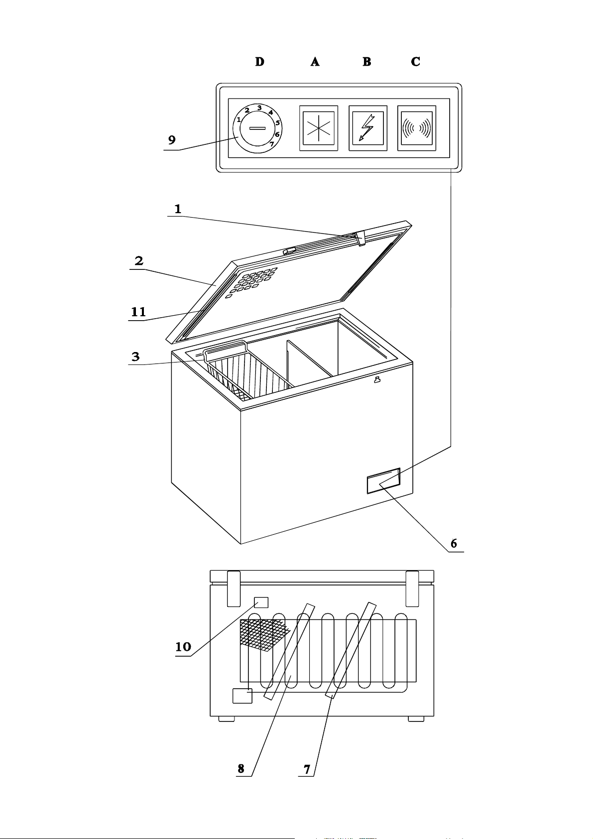
Bestandteile der Truhe sind: das Gehäuse mit Deckel und Kühlungs-system mit Automatik. Sie ist
mit Polyurethan wärmegedämmt. Der innere Mantel ist aus verzinktem Blech gefertigt, rostfrei und,
wie alle anderen sichtbaren Flächen, mit Lackierung von hoher Qualität - Plastifikation geschützt. Im
Deckel (2) kann ein Lämpchen für die Belichtung des Inneren eingebaut sein, der Handgriff (1) kann
aber mit einem Schloss oder ohne dessen ausgeführt werden. Das hermetisch geschlossene
Kühlsystem mit dem Verdampfer, der mit dem inneren Mantel der Truhe in einem direkten Kontakt
steht, gewährt eine wirksame Kühlung. Die Anlage betätigt sich vollautomatisch mittels eines
Thermostaten, der die gewünschte
temperatur reguliert.
2. AUFSTELLUNG DER GEFRIERTRUHE
Die Truhe soll in einem kühlen und trockenem Raum aufgestellt werden, wo sie keinen unmittelbaren
Sonnenstrahlen ausgesetzt sein darf. Sie muss standfestig sein, waagerecht und allen Wänden am
wenigsten 15 cm entfernt stehen. Zwecks Verminderung des elektrischen Energieaufwands wird es
empfohlen, die Truhe in so einen Raum einzubauen, wo durch das ganze Jahr eine beiläufig
gleichmässige Temperatur herrscht; ferner, dass man die Truhe ohne Bedarf nicht öffnet und dass
man die Temperatur in der Truhe überprüft - sie soll sich zwischen - 18°C und - 20°C bewegen. Sie
soll auf so einer Stelle aufgestellt werden, wo eine gute Luftzirkulation ermöglicht ist, was für eine
Truhe mit statischem Kondensator (8), der keinen Ventilator hat, besonders wichtig ist. Diese Truhe
ist, um die Beschädigungen während des Transports fernzuhalten, zwischen der Wand der Truhe und
dem Kondensator mit einer Styroporeinlage (7) versehen, die man vor dem Anschluss die zwei
Latten (11) entfernen, die zwischen dem Deckel und der Mulde der Truhe angebracht sind, um das
Dichtungsprofil vor Transportbeschädigungen zu schützen.
3. ANSCHLUSS DER GEFRIERTRUHE
!
Sollte der Stecker an der Anschlussschnur beschädigt sein, so müssen Sie die
Anschlussschnur gegen eine neue tauschen, oder zum Austausch einen Ersatzteil
verwenden, der von dem Hersteller bzw. bevollmächtigter Kundendienstservice
gewährleistet wird.
Die Truhe wird an ein 230V, 50Hz - spannungselektronetz angeschlossen, und zwar unmittelbar mit
dem Stecker in die Steckdose, die vorschriftsmässig geerdet sein muss. Die Anlage ist für
Schwankung der elektrischen Spannung sehr empfindlich. Es ist eine Abweichung von ±10% von der
Nennspannung gestattet. Es wird empfohlen, dass man im Falle grösserer Abweichungen die Truhe
an des Elektronetz über einen Netzspannungskorrektor anschliesst, womit eine ungestörte Wirkung
gewährt wird.
Die Steckdose in die der Anschlussschnurstecker des Kühlschranks eingesteckt wird, soll sich an
einem immer frei zugänglichen Platz befinden.
4. DIE SIGNALANLAGE
Im unteren Teil des äusseren Mantels befindet sich die Armaturplatte (6) mit den Schaltern.
Lämpchen und Thermostatenknopf, die den Benutzer auf die richtige tätigkeit der Gefriertruhe
aufmerksam machen.
A - Der gelbe Schalter mit einer eingedrückten Schneeflocke. Nach einem Druck darauf fängt das
gelbe Lämpchen zu brennen an, die Truhe aber setzt ihre ununterbrochene Betätigung fort,
unabhängig von der Temperatur in der Gefriertruhe. Mit einem wiederholten Druck auf den

10
Schalter wird die Zwangsbetätigung ausgeschalted und die automatische Betätigung
eingeschaltet, die vom thermostaten reguliert wird.
B - Das grüne Lämpchen mit eingedrücktem Zeichen für die elektrische Spannung signalisiert uns
die Anwesenheit der elektrischen Spannung - das grüne Licht leichtet ununterbrochen.
C - Der rote Schalter mit eingedrücktem Alermzeichen. Falls in der Truhe die Temperatur zu hoch
ist, fängt das rote Licht zu brennen an, äusserdem wird noch die Schallanlage in Bewegung
gesetzt. Man kann den Alarm mit einem Druck auf den Schalter ausschalten, debei aber brennt
noch das rote Licht weiter. Sobald das Lämpchen zu brennen aufhört, schaltet man von neuem
den Schalter um, damit man bel eventueller wiederholter Temperaturerhöhung in der
Gefriertruhe über die erlaubte Grenze vom Alarm von neuem aufmerksam gemacht wird. (Das
rote Licht mit dem eingedrückten Alarmzeichen fängt an zu brennen, wenn die Temperatur in
der Truhe zu hoch ist. Es brennt so lang, bis die Temperatur in die zulässige Grenze sinkt.)
D - Der Thermostatenknopf - mit ihm kann man mittels einer Münze die Temperatur in der Truhe
einstellen. Der Thermostat wurde zwar schon in der Fabrik für die zweckmässigste Temperatur
in der Truhe eingestellt und in normalen Betriebsverhältnissen ist es nicht nötig, ihn
umzustellen. Falls man aber in der Truhe eine andere Temperatur zu haben wünscht, kann man
das so erreichen, dass man den Thermostatenknopf in der Richtung des Uhrzeigers dreht für
niedrigere Temperaturen und in der gegensätzlichen Richtung für höhere Temperaturen in der
Truhe.
5. DAS AUFLADEN DER GEFRIERTRUHE
Es wird empfohlen, vor dem ersten Laden die Betätigung der Gefriertruhe zu überprüfen. Man soll
die Truhe an das elektrische Netz anschliessen und den Schalter ”A” niederdrücken (das gelbe Licht
brennt).
Das Innere der leeren Truhe muss die vorgeschriebene kalte Temperatur Beiläufig in zwei Stunden
erreichen. Danach umschaltet man der Schalter mit einem wiederholten Druck auf den Schalter ”A”
(das Lämpchen brennt nicht) auf die automatische Funktion - der Thermostat (9) reguliert die
Temperatur in der Truhe. Nachdem man auf diese Weise die richtige Funktion der Truhe überprüft
hat, kann man sie mit der ersten Menge von Nahrungsmittel füllen. Bei dieser Handlung muss der
Schalter ”A” in der Lage einer ununterbrochener Tätigkeit der Truhe sein (das gelbe Licht brennt).
Bei dem Laden muss man darauf achten, dass man nicht auf einmal die ganze Truhe vollfüllt, sondern
nur die tägliche Kapazität, die auf dem Beschreibungsschild (10) auf der hinteren Seite der Truhe
vorgeschrieben steht. Frisch packierte Nahrungsmittel soll man an die äussere Wände schlichten,
damit sie schneller einfrieren. Nach dem Laden der Gefriertruhe soll das gelbe Lämpchen noch
wenigstens einen Tag lang leuchten, danach soll man mit einem Druck auf den Schalter auf die
automatische Funktion umschalten.
6. STILLEGUNG DER TRUHE
Man bringt die gefriertruhe zum Stillstand so, dass man einfach den Stecker aus der Steckdose
herauszieht.
7. TAUBILDUNG AUF DER GEFRIERTRUHE

11
Die Taubildung entsteht am meisten infolge zu grosser Feuchtigkeit des Raums, in welchem die
Truhe aufgestellt ist. Die Feuchte, die sich in der Luft befindet, kondensiert sich auf dem kühleren
Körper, das heisst, auf der Truhe, so dass die Oberfläche von der Taubildung nass wird und darunter
Wasser erscheint.
In diesem Fall ist es empfehlenswert, die Truhe in einen anderen, trockenen Raum zu versetzen und
sie so aufzustellen, dass man an ihr eine bessere Luftzirkulation ermöglicht.
Man soll die Truhe von der Wand antfernt aufstellen und etwas unterlegen.
8. GLÜHLAMPENWECHEL (falls sie eingebaut ist)
Wenn die Glühlampe durchbrennt, wechselt man sie, und zwar so, dass man zuerst die Truhe
ausschaltet, danach drückt man den Schutzschild der Glühlampe in der Richtung der längeren Seite.
Auf diese Art kann man den Schutzschild vom Deckel abstellen. Die neue Glühlampe muss eine
Gewinde E 14 und Kraft 10 W haben.
9. REINIGUNG DES KONDENSATORS
Der Kondensator soll jährlich ein - bis zweimal gereinigt werden, und zwar so, dass man die Truhe
ausschliesst und den Kondensator mit einer weichen Bürste oder mit Staubsauger reinigt. Bei der
Reinigung eines dynamischen Kondensators (mit Ventilator) muss man vorher das Netz des
Aggregatenraums, welches den Zutritt zum Kühlaggregat verhindert, demontieren, während bei der
Reinigung eines statischen Kondensators dies nicht nötig ist, weil derselbe auf die hintere Seitenwand
der Gefriertruhe befestigt ist.
10. ABSCHMELZEN UND REINIGUNG
Nach einer gewissen Zeit sammelt sich auf dem inneren Mantel Rauhreif an, den man antfernen muss,
und zwar am wenigsten zweimal jährlich.
Zuerst muss man die Truhe ausschliessen, dann den Deckel öffnen, die Nahrungsmittel dicht in
Körbchen (3) einpacken, in einen kühlen Raum stellen und dick mit Zeitungspapier, einer Decke oder
anderem entsprechendem Isolationsmaterial einwickein. Von den inneren Wänden entfernt man im
rohen den Rauhreif mittels eines Schabers ab, der in der Truhe beigelegt ist.
Nach dem Abschmelzen reinigt man die Truhe mit lauwarmem Wasser mit Zusatz von mildem
Reinigungsmittel, danach trocknet man sie mit einem weichen Lappen ab und lässt sie noch einige
Zeit offen, damit sie ganz trocken wird.
Das Abschmelzverfahren kann man damit beschleunigen, dass man nach der rohen Entfernung des
Rauhreifs in die Truhe ein Gafäss mit kochendem Wasser stellt und die Truhe für einige Minuten
zumacht (solange bis der ganze Rauhreif abfällt).
Man schmelzt die Truhe nach Möglichkeit dann ab, wenn sich in ihr wenigste Nahrungsmittel
befinden.
11. BESCHÄDIGUNG
Es wird empfohlen, die Truhe regelmässig zu kontrollieren.
Die Kontrollämpchen auf der Armaturplatte machen den Benutzer auf die funktionsfähigkeit der
Truhe aufmerksam.
a) Wenn kein Lämpchen brennt, ist wahrscheinlich eine Unterbrechung des elektrischen Stromes
eingetreten. In diesem Fall muss man die Sicherung und die Steckdose kontrollieren. Wenn das

12
grüne Licht nicht brennt, es brennen aber das orangegelbe und das rote, ist das grüne verdorben
und man muss es wechseln.
b) Wenn die Steckdose unter elektrischer Spannung ist die Signallampen aber brennen nicht, sollen
Sie die nächste Servicestation rufen. Die sollen tur auch im Fall, wenn die rote Lampe brennt, es
sei denn in Fällen, die in diesen Anweisungen angeführt sind und wenn dies normal ist.
c) Im Fall des Ausfalles vom elektrischen Strom oder einer Beschädigung soll man die Truhe nicht
aufmachen, um in ihr längere Zeit (24 bis 30 Stunden) eine niedrige Temperatur zu behalten, und
die Angst, dass die Nahrungsmittel in ihr verdorben werden, zu entfernen.
ACHTUNG!
Wenn Sie die Truhe langere Zeit nicht brauchen, oder sie mit einer anderen austauschen wollen,
werden Sie gebeten, dafür Vorsorge zu tragen, dass Schloss unbrauchbar wird. So werden Sie
Unglücksfälle von
Kinderen, die sich beim Spielen in die Truhe einsperren möchten, verhindern.
WIR GEBEN DIESE ANWEISUNGEN BEKANNT MIT VORBEHALT DES RECHTES AUF
TECHNISCHE ÄNDERUNGEN, DIE DIE FUNKTION DES APPARATES NICHT
BEEINFLUSSEN.
ENTSORGUNG, AUßERBETRIEBNAHME
Die Ensorgung der Produkte nach Wegfall der Nutzung ist umweltverträglich. Das Erzeugnis ist in
dem Fall am spezialisirte Firma zur komplette Entsorgung zu schicken.
Sonst sind die Einzelheiten der Entsorgung und Wiedervenwendbarkeit der Bauelemente der
folgenden Übersicht zu entnehmen.
Produkt Materialien Entsorgung
Stahlkonstruktionen
Gestelle
Motore
Lüfträder
Rohrleitunge
Laden
Metalle
Trennung der Materialien
Zuführung zur Wieder-
verwertung durch
Einschmelzung
Isoliertes Gehäuse
Isolierte Türe Metalle, PU Schaum Trennung der Materialien
Spezielles Verbrennung
Kabel
Gehause Stecker
Gummi, PVC, Silikon,
änliche Kunststoffe Trennung der Materialien
Zuführung zu Wieder-
verwertung
Elektronik Baugrupen
Kunststoffe, Metalle,
Elektrolyte Auf Sonderdeponien unter
Beachtung örtlicher
behördlicher Vorschriften
Produkte mit Anstrichen sind entsprechend dem Anstrichmaterial der Wiederverwertung zuzuführen
oder unter Beachtung örtlicher behördlicher Vorschriften auf Sonderdeponien zu entsorgen.
ÜBEREINSTIMMUNGSERKLÄRUNG

13
Hersteller, Aktiengesellschaft:
LTH Škofja Loka d.d., Kidrieva 66, 4220 Škofja Loka
Erklärt hiermit, dass die Produkte:
GEFRIERTRUHE
mit Typenbezeichnung:
ZS 220, 300; 380; 530
Entsprechen:
-der Verordnung über elektrische Ausrüstung zur Anwendung in den festgelegten
Spannungsgrenzen (LVD) EGS/73/23 - 93/68
-den Regeln über elektromagnetische Kompatabilität (EMC) EGS/89/336 - 93/68
Dabei wurden die folgenden Standards und Spezifikationen berücksichtigt:
- EN 60335-1:1988
- EN 60335-2-24:1994
- EN 55014-1: 2000+A1: 2001+A2: 2002
- EN 55014-2: 1997+A1: 2001
- EN 61000-3-2: 2000
- EN 61000-3-3: 1995+A1: 2001
Škofja Loka, 7. 1. 2004 ____________________
Direktor
1. CARACTERISTIQUES DE L’ARMOIRE-CAISSE
FRIGORIFIQUE

14
La caisse est composée de la charpente avec couvercle et du systme réfrigrant automatique. La
chaleur est isolée avec du polyuréthan. Le revtement intérieur est fabriqué avec du fer-blanc zingué,
résistant la rouille et protégé par une laque plastifiée de qualité, comme toutes les surfaces visibles.
Le couvercle (2) peut tre muni d’une lampe pour éclairer l’intérieur de la caisse, la poignée (1) est
avec ou sans serrure. Le systme de réfrigération par évaporation est hermétiquement fermé et a un
contact direct avec le revtement intérieur de la caisse ce qui lui assure une capacité de production
de froid trs satisfaisante. Le fonctionnement de l’appareil est entirement automatisé au moyen d’un
thermostat lequel sert régler la température selon les besoins.
2. EMPLACEMENT DE LA CAISSE FRIGORIFIQUE
La caisse doit tre placée dans un endroit froid et sec, et ne doit pas tre exposeée aux rayons
solaires directs. Elle doit tre stable, sur une surface unie en position horizontale et éloignée de tous
les murs environnants, au moins, de 15 cm. Nous conseillons de placer la caisse frigorifique dans un
endroit qui a durant toute l’année une température constante ou presque égale pour consommer
moins d’énergie électrique. Pour la mme raison économique, il ne faut pas ouvrir la caisse sans
nécessité et contrôler la temperature qui doit osciller entre - 18°C et - 20°C. Il est spécialement
recommandé et trs important de placer la caisse frigorifique condensateur statique (8), dans un
endroit bien aéré et assurer une bonne circulation de l’air car ces caisses sant ventil teur. Un soutien
ou support en styrolne est inséré, pour le transport, entre les murs de la caisse et le condensateur
(7) il faut veiller l’enlever avant de brancher l’appareil. De mme pour protéger la caisse des heurts
et chocs, ou tout autre dégât occasionné par ou durant le transport, deux lattes sont placées entre le
couvercle et la cavité de la caisse pour les contours qui risquent d’tre d’tre déformés, il faudra
donc les enlever avant l’embranchement.
3. BRANCHEMENT DE LA CAISSE FRIGORIFIQUE
!
Si la fiche du cordon d'alimentation est endommagée, elle doit être remplacée
entièrement avec la pièce, assurée par le fabricant ou par le service après-vente agréé.
La caisse est branchée au réseau électrique d’une tension de 230 V, 50 Hz, directement avec la fiche
dans la price de courant. La prise de courant doit avoir un contact avec le sol selon les instructions et
rglements en vigueur. L’installation est sensible la vibration de la tension électrique. La déviation
permise est ±10% de la tension initiale. Dans le cas de déviations cessions cessions répétées nous
recommandons d’établir le courant de la caisse au réseau électrique au moyen d’un correcteur de la
tension du réseau, avec lequel nous assurons un fonctionnement ininterrompou.
La prise de courant dans laquelle on branche la fiche de raccordement du réfrigérateur doit se
trouver à l'endroit qui est toujours librement accessible.
4. LES SIGNAUX
A la partie inférieure droite de la surface externe il y a une planche armature (6) munie d’une prise de
courant, de signaux lumineux et du bouton du thermostat qui nous aident contrôler et nous
assurer du fonctionnement juste et correct de la caisse frigorifique.

15
A - La prise jaune est marquée d’un flocon de neige. Si on appuiesur la prise une lumire jaune
s’allume, l’appareil fonctionne sans interruption, indépendamment de la température de la caisse
frigrifique. En répétant la pression sur la prise, la force coercitive est coupée et le
fonctionnement automatique est branché et sera réglé par le thermostat.
B - La lumire verte est marquée d’un signe de tension électrique et ainsi nous signale la présence
de tension électrique. La lumire verte est allumée sans interruption.
C - La prise rouge est marquée d’un signal d’alarme. Quand la température est trop élevée dans la
caisse frigrifique, la lumire rouge s’allume et déclenche le signal d’alarme. Pour couper le son
de la sirne d’alarme il faut appuyer sur la prise, cependant la lumire rouge reste allumée.
Quand elle s’éteindra, nous brancherons de température dans la caisse frigorifique le signal
d’alarme nous signalera de nouveau ce dérglement. La lumire de la prise rouge marquée d’un
signal d’alarme s’allume quand la température dans la caisse est trop élevée. La lumire reste
allumée jusque que la température baisse aux limites permises.
D - Le bouton du thermostat avec lequel nous réglons l température dans la caisse en nous servant
d’une pice de monnaie pour tourner le bouton. Bien qu’il n’est pas nécessarie de transposer ou
changer la température indiquée sur le thermostat can la livraison de la fabrique elle est réglée
pour un fonctionnement normal bien adapté en général. Mais si, malgré tout, on désire un
changement il faut tourner le bouton du thermostat dans le sens des aiguilles de la montre pour
obtenir une température plus basse et dans le sens contraire pour obtenir une température plus
élevée.
5. LE REPLISSAGE DE LA CAISSE FRIGORIFIQUE
Nous conseillons de vous assurer du bon fonctionnement de la caisse frigrifique avant de vous en
servir, pour la premire fois. Branchez l’appareil au réseau électrique et pressez sur la prise de
contact ”A” (la lumire jaune luit).
L’intérieur de la caisse vide doit tre refroidi la température conforme aux instructions pendant
deux heures environ avant le premier usage Ensuite, par pression, de nouveau, sur la prise de contact
”A”, nous inversons le courant (la lumire s’éteint s’éteint) du fonctionnement automatique. Le
thermostat (9) rgle la température dans la caisse. Aprs. Aprs avoir contrôlé le bon fonctionnement
de la caisse frigorifique, dans ce cas, alors, vous pouver la remplir de la premire quantité d’aliments.
Dans ce cas, dans la caisse, la prise de contact ”A” doit tre en position de fonctionnement
ininterrompu (la lumire jaune luit). Evitez de remplir toute la caisse en une seule fois, mais plutôt
une quantité partielle de la capacité indiquée sur le tableau (10) au dos de la caisse. Les aliments frais
bien empaquetés doivent tre rangés contre les murs externes pour une réfrigération rapide. Laissez
la lumire jaune allumée pendant au moins un jour aprs avoir rempli la caisse frigorifique. Ensuite,
appuyez en pressant sur la prise de contact pour inverser le courant au fonctionnement automatique.
6. ARRET DU FONCTIONNEMENT
Trs simplement, en retirant la fiche de la prise de courant, nous arretons le fonctionnement de la
caisse frigorifique.
7. BUEE QUI SE FORME DANS LES CAISSES FRIGORIFIQUES
Cette buée est provoquée le plus souvent par l’emplacement de la caisse dans un endroit grande
humidité. L’humidité qui est dans l’air condensé se pose sur un corps plus froid (dans ce cas la
caisse) qui est couverte de buée et l’eau apparaît dessous.

16
Pour remédier cet inconvénient, nous conseillons de déplacer la caisse pour un autre endroit plus
sec, et de l poser dans une place oil est possible d’obtenir une meilleure circulation d’air.
Eloignez la caisse des murs et posez dessous quelque support.
8. CHANGEMENT DE LAMPE (si elle est installée)
Si l’ampoule électrique est brulée, il faudra tout d’abord coupe le courant dans la caisse. Pour la
changer ou plutôt pour l’extraire, on appuie sur la rondelle protectrice de la lampe dans le sens du
côté le plus long. De cette facon nous pouvons dégager la rondelle du couvercle. La nouvelle lampe
doit avoir une spire E 14 et puissance de 10 W.
9. NETTOYAGE DU CONDENSATEUR
Une ou deux fois par an nous nettoyons le condensateur. Aprs avoir coupé le courant dans la caisse,
nous nettoyons le condensateur avec une brosse douce ou avec un aspirateur pour poussire. Pour le
nettoyage d’un condensateur dynamique (avec ventilateur) nous devons d’abord démonter le filet de
la place de l’agrégat, qui protge en empéchant l’accs l’agrégat frigorifique, pendant que, pour
nettoyer le condensateur statique il n’est pas nécessaire de démonter de filet car il est fixé l’arrire
de la caisse frigorifique.
10. DEGIVRAGE ET NETTOYAGE
Aprs un temps déterminé, la glace s’amasse sur le revtement intérieur. Il faut faire un dégivrage au
moins deux fois par an.
Tout d’abord il faut couper le courant dans la caisse, ensuite ouvrir le couvercle et entasser les
aliments dans une corbeille (3). Poser la corbeille dans un lieu froid et bien envelopper le tout avec
plusieurs couches de papier journal, couvertures ou tout autre matériel izolant convenable. A
l’intérieur des murs, il faut enlever la glace formée avec un racloir range dans la caisse.
Aprs le dégivrage, on nettoie la caisse avec de l’eau tide laquelle on aura ajouté un peu de
détergent doux, on essuie le tout avec un torchon doux et on laisse ouvert pendant un certain tout
pour sécher compltement.
Pour accélérer l’opération de dégivrage, on place dans la caisse, aprs avoir enlevé la glace avec le
racloir, un pot d’eau bouillante et on ferme la caisse pendant quelques minutes (jusqu’la fonte
complte de la glace).
S’il est possible, faire le dégivrage quand la caisse ne contient pas une grande quantité d’aliments.
11. DEGATS
On prévient les dégâts par un contrôle régulier.
Les signaux lumineux pour contrôle lesquels se trouvent dans la planche-armature servent attirer
l’attention du consommateur ou celui qui l’utilisesur le bon fonctionnement de la caisse frigorifique.
a) Si aucune lumire ne luit: cela peut tre causé par une interromtion du courant électrique. Dans
ce cas il faut controler les fusibles et la prise de courant. Si la lumire verte est éteinte, la lumire
orange et, rouge luisent, le vert est brulé il est necessaire de le changer.
b) La prise de contact est sous tension électrique, les si gnaux lumineux sont éteints, il faut
contacter le poste service aprsvente le plus prs. De mme, vous aurez recours au service si la
lumire rouge luit. Excepté dans les cas qui sont mentionnés dans ce mode d’emploi et que les
signaux sont normallement allumés.

17
c) Dans le cas d’interruption de courant ou tout autre dérangement dans le réseau électrique, ne pas
ouvrir la caisse, pour conserver le froid le plus longtemps possible (24 heures). Il n’y a aucune
crainte pour que les aliments soient altérs.
ATTENTION!
Pour prévenir tout accident éventuel, les enfants qui par jeu se cachent et s’enferment dans la
caisse, nous vous prions d’exclure la serrure ou de la rendre inutilisable si vous avez l’intention
d’échenger votre caisse frigorifique pour une autre nouvelle ou si vous ne voulez pas vous en
servir pendant un temps prolongé.
NOUS NOUS RESERVONS LE DRCIT DE TRANSFORMATIONS TECHNIQUES QUI
N’INFLUENT PAS SUR LE FONCTIONNEMENT DE L’APPAREIL.
ELIMINATION DE L'APPAREILAPRES SA MISEHORS DE SERVICE
L'élimination de l'appareil aprs sa mise hors de service doit respecter l'environnement. L'appareil
doit tre remis l'entreprise qui est spécialisée pour son élimination totale.
Le tableau ci-dessous illustre l'élimination dans tous ses détails, ainsi que la réutilisation de chacun
des éléments constitutifs de l'appareil:
appareil matire élimination
construction d'acier
bâti
moteurs
hélices
tuyauterie
compartiments
métaux
séparation des matires
procédure de fusion pour
réemploi (recyclage)
bâtis isolés
portes isolées métaux, mousse PU séparation des matires,
incinération spéciale
câbles
bâtis, fiches caoutchouc, PVC, silicone,
substances artificielles
similaires
séparation des matires,
recyclage
groupes composantes
électroniques masses artificielles, métaux,
électrolytes évacuation dans des décharges
de déchets spéciaux,
conformément aux prescriptions
en vigueur.
Les pices recouvertes d'enduits sont soit soumises tranformation pour réemploi, en fonction du
type d'enduit, soit évacuées dans des décharges de déchets spéciaux, comme stipulé par les
prescriptions locales.
DECLARATION DE CONFORMITE
Le producteur, société anonyme:
LTH Škofja Loka d.d., Kidrieva 66, 4220 Škofja Loka

18
déclare que produits:
CONGELATEUR COFFRE
du typ :
ZS 220; 300; 380; 530
sont conformes
:
-au règlement concernant l´équipement électrique destiné à être utilisé dans les limites de
tension définies (LVD) EGS/73/23 – 93/68
-au règlement sur la compatibilité électromagnétique (EMC) EGS/89/336 – 93/68.
Les standards et les spécifications suivants ont été observés:
- EN 60335-1:1988
- EN 60335-2-24:1994
- EN 55014-1: 2000+A1: 2001+A2: 2002
- EN 55014-2: 1997+A1: 2001
- EN 61000-3-2: 2000
- EN 61000-3-3: 1995+A1: 2001
Škofja Loka, 7. 1. 2004 ____________________
Direktor
This manual suits for next models
4
Table of contents
Languages: