Lumag HGS50058 User manual

Distribution Limited
Petrol Flail Mower
Operator’s Manual
HGS50058
FOR YOUR SAFETY
READ AND UNDERSTAND THE ENTIRE MANUAL
BEFORE OPERATING THIS MACHINE


Warranty Registration Form
For the warranty to be valid the Warranty Registration Form must be completed and
returned to Lumag Distribution Limited within 14 days of the purchase, together
with a copy of the purchase invoice.
We will use your email to confirm that we have received the completed Warranty
Registration Form and contact you about any errors or omissions on the form. We
may occasionally use this email address to make you aware of news, technical advice
and special offers. If you do not wish to receive such emails please tick this box.
Unit 10, Hatchmoor Industrial Estate, Hatherleigh, Okehampton, Devon EX20 3LP
www.lumag-gb.co.uk 01837 811741
Lumag Distribution Limited Company Number: 09267547 VAT Number: GB154566788 Hatherleigh
Plant and Tool Hire is a trading name of Lumag Distribution LTD
Model:
Serial Number:
Type of Use: Business / Domesc
Name:
Business Name:
Address:
Email Address:
Phone Number:
Date of Purchase:
Place of Purchase:
Proof of Purchase
enclosed:


Lumag Servicing and
Maintenance Schedules
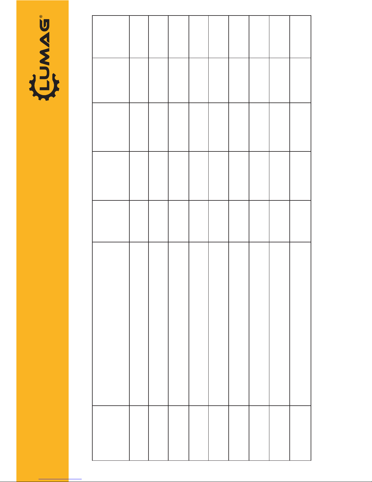
Engine Service & Maintenance Schedule
Machine Service & Maintenance Schedule
Item Checks/Work Each Use 20hrs
(1st Month)
50hrs
(2nd Month)
100hrs
(6th Month)
300hrs
(Yearly)
Engine Oil Check Level X
Change X (1) X
Air Filter Check X
Clean X (3)
Replace X (4)
Sediment Cup Clean X
Spark Plug Check/Clean X
Replace X
Idle Speed Check/Adjust X (2)
Valve Clearance Check/Adjust X (2)
Fuel Tank Strainer Check/Clean X (2)
Combuster Chamber Inspect/Clean X (2)
Fuel Lines Check X (2)
Item Checks/Work Each Use Weekly 20hrs
(1st Month)
50hrs
(2nd Month)
100hrs
(6th Month)
300hrs
(Yearly)
Fasteners Tension Check X
Clean Machine Clean X
Drive Belt Check/Adjust X
Replace X (2)
All Other Moving Parts &
Cables
Lubricate X X (2)
Engine Oil 750ml Lumag Engine 1
1 – First service only, 2 = Should be carried out by your Lumag Dealer, 3 = May need to be done more oen in dusty areas &
4 = Replace paper element only
To maximise the life of your Lumag machine it needs to be serviced and maintained at every indicated month or
operang hour interval, whichever comes rst, in accordance with the below Schedules. Please note that failure to
service your machine on schedule or use genuine Lumag parts and consumables will result in your warranty being void.

Distribution Limited
Service & Maintenance Record
Product Details: Model: __________________________________
Serial number: ____________________________
Purchase Date: ____________________________
Date:
Description of checks/work carried out:
Parts Used?
Y/N
Parts Invoice
Number:
Dealers
Name:
Engineers
Name:
Engineers
Signature:
Please note that failure to service your machine on schedule or use genuine
Lumag parts and consumables will result in your warranty being void


-26-


1. Subject of warranty
The warranty applies to products and goods
supplied by MOTOR JIKOV Strojirenska a.s.
2. Warranty period
The basic warranty period provided is 24 months
from the date of sale to the purchaser, unless
otherwise specified in the respective warranty
certificate. The period from application of the right
following from damage liability to compulsory
takeover of the repaired object is excluded from
the 24-month warranty period. The seller shall
submit to the buyer written confirmation of the
warranty right application, of the repair performed
and the period of time it consumed. In the case of
product replacement the warranty period of the
replaced assembly set will be the whole 24
months from the date of the repaired product
takeover.
3. Scope of manufacturer's responsibility
The manufacturer is responsible for qualities of
the product throughout the warranty period. The
qualities will be as usual for this type of product
and its specifications. The manufacturer shall not
be liable for product defects caused by regular
wear and tear or by use of the product for
purposes other than designed.
i) The defects claimed have been caused by
unprofessional product storage
j) The defects claimed have resulted from usual
wear and tear following from regular use
k) The product has been combined or operated
with a device not approved by the manufacturer
5. Warranty claim application
Warranty claim is applied by the buyer with the
seller. The buyer placing a complaint shall submit
the properly filled out warranty certificate of the
product. Warranty repairs shall be performed by
the seller or by an authorised service shop of the
seller. The buyer shall contact the nearest autho-
rised service shop of the seller.
6. Exceptions from warranty
The guarantee shall not apply wear and tear of
the parts resulting from the ordinary use of thing
that are usually replaced in the courses of the
prescribed maintenance. This concerns,
in particular, harvester mowin knives, V-belts,
ingnition plugs (sparks) and air filters.
4. Cancellation of warranty
The warranty claim is cancelled if:
a)
The product is not used and maintained pur-
suant to its instruction for use or damaged by
unauthorised interference of the use
r
b)
The product has been used under conditions
or for purposes other than designed
c)
The customer is unable to submit the product
warranty certificate
d)
The data specified by the manufacturer, dealer
or service shop in the original product documen
-
tation have
been intentionally overwritten
e)
Any product part has been replaced with a
part other than a original part supplied by he
manufacturer
f)
The product has been damaged due to insu-
fficient maintenance
g)
The product has had an accident or has been
damaged by force
majeure
h)
The product has been altered without the
manufacturer's approval
-25-

Dismantle the drive wheels from the
axle at the end of the season, clean them and fill
the cartridge with a new fill of plastic lubricant.
Lubricate also the wheel front with the balls and
the freewheel section (4) (fig. 8). When assem-
bling the machine again never tighten the nut
with the maximum torque, the wheel must turn
slightly. Provide the nut with a new lock pin
Lubricate the lines with silicon oil.
8. Decommissioning
After every mowing let the engine cool,
clear the stuck grass and lubricant residues.
When mowing in a dusty environment take the
plastic cover off the BDR 582 engine and clean
the cylinder blades.
Inspect the mower, Replace worn or damaged
parts. Tighten all bolted joints with maximum
torque.
9. Machine storage
Let the engine cool. Clean and wash the
machine (not with pressurised water) to clear gra
-
ss, lubricant and fuel residues. Check all bolted
joints for tightening to provide for a functional and
safe machine.
Check the machine and replace all worn or dam
-
aged parts as needed. Never store the machine
with any fuel in the tank inside the building where
the petrol vapour might reach open fire or
sparks.
If storing the machine without fuel, empty the fuel
tank in an open space and into a barrel designed
for fuel repository, and observe the relevant regu
-
lations for safe storage of petrol. Conserve the
engine surface and other parts of the machine
that might get corroded.
Place the machine in a sheltered ventilated room
and protect against weather and humidity.
The mower must be within the safety distance
from substances causing corrosion such as gar
-
den chemicals or defrosting salts.
Storage or placement of the products
on free uncontrolled dumps is legally prohibited,
including release of technical fluids into a natural
source or to sewerage.
7. Machine lubrication
Paper wrappers:
- return for recycling to collection points
- place in paper containers for sorted waste
- incinerate
Plastic wrappers:
- place in plastic containers for sorted waste
Wood:
- incinerate or crush
-24-
If the machine is not to be used any more you
must release the fuel and the oil fill into closed
containers. The machine may then be stored or
provided to a professional organisation for phy-
sical liquidation, including the technical fluids.

Before knife replacement and before
every check of the mowing gear always disco-
nnect the power terminal from the ignition spark.
Release and fully dismantle the nut (2)(fig. 11).
and remove the washer (6). When taking out the
screw (1) hold the knife (3) and take the screw
out through the auxiliary opening in the bottom
disc (4). Remove the knife, turn it round and
assemble again (the knife is sharpened on both
sides). When both side cutting edges are insuffi-
ciently sharp sharpen the edges and level the
knife if slightly bent. Replace the knife with a
new one if seriously damaged or extensively bent.
Some mowers have the nuts secured with a lock
pin. Remove the lock pin before dismantling and
replace with a new one when assembling the
connection again.
i Never use the machine without a com-
plete set of the knives! All assembled parts must
be original, supplied by the manufacturer.
2. V-belt tightening and check of rotor belt
tightening mechanism
> Place the mower on a work table. Fix
the wheels with wedges to prevent spontaneous
move of the mower.
Dismantle the bottom cover (5) (fig. 10) loosen
the nuts (2) and tighten the drive belt (9) with the
nut (3). The belt should be tightened to provide
for 10-15 mm slack and for clearance of the rotor
drive belt (8). Tighten the nut (2) and replace the
cover (5). Never tighten the belt without released
nuts (2).
Take off the plastic cover covering the mower
front. Check correct adjustment of the tightening
pulley of the drive belt in relation to the mower
box once a month, depending on the mower ope-
ration. When placing a ruler on the upper face of
the opening in the box (fig. 12) the upper side of
the pulley lining (1) should be about 8 mm below
the box level. Adjust the position with mechanical
bending. With fully depressed lever on the
right-hand handlebar the pulley must sufficiently
tighten the belt (the spring on the rod must be
pressed by about 2 mm in comparison to the nor-
mal state). When the belt is turning the pulley
must not oscillate. Remove the pulley oscillation
with the adjustment bolt (1)(fig. 7) and the lever
bolt (3) (fig. 4, 5, 13)
Move of the machine is adjusted with the
adjustment bolt on the lever line (1) (fig. 4,5,13) or with
the bolt (2) (fig. 7) with the result that when the
move lever is engaged the machine cannot
be reversed.
4. Belt replacement
i Place the mower on a work table. Fix the
wheels with wedges to prevent spontaneous move
of the mower. Dismantle the plastic cover from the
mower. Dismantle the bottom cover (5) and loosen
the V-belt tightening union (4) (fig. 10) with nuts (2)
and (3). Shift the engine towards the mowing gear
and replace the move belt (9). Dismantle the belt
tightening union (4) and remove the rotor belt (8)
from the pulley (10). Dismantle the rotor pulley
from the cartridge (3 M6 bolts, 3 M6 nuts, fig. 11)
and pull the belt out of the box. The assembly is
to be done in the reverse order. Tighten the move
belt pursuant to Chapter VI/2. Before replacing the
plastic cover check operation of the tightening pu-
lley pursuant to chapter VI/2.
When changing the drive belt of the mowing rotor,
performing the role of the clutch, use exclusively
original belts supplied by the manufacturer or
assembled by an authorised service shop of
MOTOR JIKOV. The manufacturer takes no res-
ponsibility for correct operation of the transmission
if you use another belt.
5. Engine
'When operating the engine follow the
instruction for use of the particular engine type.
6. Transmission
kThe transmission box is filled with per-
manent transmission oil of SAE 90 class. When
cleaning the mower a check for leak of the oil
from the transmission box is recommended. Per-
form the check via the two little windows in the
real wall of the box (6) (fig. 10)
In the case of detected leak replace the worn
shaft sealing rings. The replacement should be
done by an authorised service centre.
1. Mowing knife replacement
3. Move adjustment
-23-

In the case of emergency release both
levers on the handlebar immediately.
The levers will return to the zero position, the
machine will stop and the safety brake will stop
the mowing rotor in a very short time.
3. Operating lawn mowers 5316SBE, 5316SPE
Move the accelerator control
lever on the right
handlebar to MAX position. Start the engine. Follow
the instructions in the engine instruction manual.
When starting the engine, both clutch levers (1) and
(3) fig. 5 on the handlebars shall be released. Set
max. revolutions of the engin
e by the accelerator
lever. Hold the handlebar grips. Press the lever with
the safety catch (3) fig. 5 on the right handlebar.
Press the lever very slowly by two thirds so that the
mowing rotor can start turning and the engine does
not stop. The starting o
f the mowing rotor is accom-
panied by partial slipping of the V
-belt and relating
phenomena (rattling, screeching). Upon complete
start
-up of the rotor, press the lever fully towards the
grip. The propelling mechanism is actuated by
means of the lever (1)
fig. 5 on the left handlebar.
Press the lever towards the grip, and the machine
will start moving.
6. Stopping lawn mower 5316SLE
If you operate the machine with the horizontal bar
tilted down (4) fig. 13, hold the lever (3) fig. 13 by
your right hand and release the grab handle, or re-
lease the lever (1) fig. 13 by your left hand, and the
machine will stop moving. Release the right lever (3)
fig. 13 slowly to switch off the mowing rotor drive.
When turning or backing with the machine, the mo-
wing rotor need not be stopped so as not to waste
the energy of the turning rotor. Switch the engine off
by moving the accelerator lever (2) fig. 13 to MIN or
STOP position.
The procedure of adjusting the position of handlebars
1 .Loosen the lever of a clamp joint no. 1 by one revolution
2. Loosen
the lever of position no. 2 arrest by 3
revolutions
3. Adjust
the handlebars to required position
yellow arrows
on the tube of the upper part point at the yellow division
of individual positions on the lower part.
4. Tighten the lever of position no. 2 arrest.
5. Tighten the lever of clamp joint no. 1.
HANDLEBAR POSITION SIDE ADJUSTMENT RIGHT
HANDLEBAR POSITION HEIGHT ADJUSTMENT I
-22-
4. Stopping lawn mowers 5316SE, 5316SPE
Release the left lever (1) fig. 5, and the machine
will stop moving. Release the right lever (3) fig. 5
slowly to switch off the mowing rotor drive. When
turning or backing with the machine, the mowing
rotor need not be stopped so as not to waste the
energy of the turning rotor. Switch the engine off by
moving the accelerator lever to MIN or STOP position.
5. Operating lawn mower 5316SLE
Move the accelerator control lever (2) fig. 13 on the
right handlebar to MAX position. Start the engine.
Follow the instructions in the engine instruction ma-
nual. When starting the engine, both clutch levers
(1) and (3) fig. 13 on the handlebars shall be re-
leased. Set max. revolutions of the engine by the
accelerator lever. Hold the handlebar grips. Press
the lever with the safety catch (3) fig. 13 on the right
handlebar. Press the lever very slowly by two thirds
so that the mowing rotor can start turning and the
engine does not stop. The starting of the mowing
rotor is accompanied by partial slipping of the V-belt
and relating phenomena (rattling, screeching). Upon
complete start-up of the rotor, press the lever fully
towards the grip. The propelling mechanism is
actuated by means of the lever (1) fig. 13 on the left
handlebar. Press the lever towards the grip, and the
machine will start moving. When mowing, you can
make use of a tilting horizontal bar (4) fig. 13, and
operate the machine by one hand.
HANDLEBAR POSITION TRANSPORT

The machine is designed for mowing
high-grown stands of stalk grass and thin
self-sowed plants of non-ligneous nature in
maintained areas. It is not intended for park
treatment of grass stands. Grass is cut by three
rotating knives of a mowing rotor at high periphe-
ral speed, and it is thrown out to a canvas, where
it is windrowed. When going round the area mo-
wed, the direction of mowing shall always be anti-
clockwise so that the rotor throws the grass to the
right side which is already mowed. If the stand
mowed is very thick, overgrown, rotten or de-
pressed, the swath shall be reduced accordingly
to prevent the accumulation of the grass in front
of the machine. If such situation occurs, stop the
machine and the mowing rotor will throw out the
grass accumulated. However, if the space
between the mowing rotor and the machine be-
comes clogged, stop, turn the engine off and clean
the space. The height of the stubble is given by
the lower disc, and cannot be modified. The disc
copies the surface, and that is why the stubble
height may not be regular when mowing extremely
uneven areas. While mowing, the lower disc shall
always be pressed to the ground, and it shall not
bounce.
Before first starting the engine check the
engine oil level with the dip gauge and replenish
oil if necessary.
1. Installation of canvas holder
Push the canvas arm with the canvas on into the
right wheel hinge.
2. Handlebar adjustment
Use the lever and the nut to adjust position of the
handlebar (1) (fig. 2). Place the nut lever in the
upper position so that it does not prevent starting
the engine.
______ Check tightness and faultlessness of the
mowing rotor knives.
3. Adjusting the handlebars on mower 5316SLE
The construction of the handlebars allows both
height and side adjustments, which is useful when
mowing close to walls, fences, stands etc. The
transport position of tilted handlebars makes it
possible to load the mower in the passenger car boot
easily.
1. Operating lawn mowers 5316SE
Press the clutch lever (1) fig. 4 on the left handlebar
so that it is secured by the safety catch (2). Now the
propelling mechanism of the mower is off. Move the
accelerator lever on the right handlebar to START or
MAX position fig. 6. Switch the engine on according
to the engine instruction manual. Set max. revolutions
of the engine by means of the accelerator lever. Hold
the grips of the handlebars. Press the lever with the
safety catch (3) fig. 4 on the right handlebar. Press
the lever very slowly by two thirds so that the mowing
rotor can start turning and the engine does not stop.
The starting of the mowing rotor is accompanied by
partial slipping of the V-belt and relating phenomena
(rattling, screeching). Upon complete start-up of the
rotor, press the lever fully towards the grip. Release
the clutch lever (1) by means of the safety catch (2),
and the mower will start moving.
2. Stopping lawn mowers 5316SE
Press the clutch lever (1) fig. 4, and the mower will
stop moving. Release the right lever (3) fig. 4 slowly
to switch off the mowing rotor drive. Move the acce-
lerator lever to STOP or MIN position fig. 6. The mo-
wer shall only be stopped by means of releasing the
rotor brake lever in emergency cases.
■21

Business Name
BDR 582
BDR 583
Order Number
5316 SE
5316 SBE
5316 SPE
5316 SLE
Length
1360 mm
1400 mm
Height
960 mm
1020 mm
1210 mm
Transport Height
650 mm
710 mm
Width
620 mm
620 mm
620 mm
660 mm
Weight
58 kg
60 kg
63 kg
64 kg
Maximum Reach
580 mm
580 mm
580 mm
640 mm
Driver Wheel
ANO
Engine
Briggs
Stratton
650 Series
Briggs Stratton
650 Series
Briggs Stratton
850 Series
Honda GCV 160
Engine Power (kW)
4,1
4,1
4,4
4,1
Max.Engine Speed (rev./min)
3000
3000
3000
3000
Acoustic Pressure at Operators Place La
(die CSN EN ISO 11 201) (dB)
79,7
79,9
79,6
77
Resulting Weighed Value of Vibrations
(die CSN EN 836+A1 changeA2) (m/s2)
4,7
4,7
2,7
1,5
Guaranteed Level of acoustic Performace Lwa
(die CSN ISO 11 094) (dB)
91
92
92
90
-20-

The user takes full responsibility for inju-
ries of other persons or damage to their property
by the mower. That is why the operator must wa-
tch for other persons' and animals' movement
within the reach of the operated machine. The mi-
nimum safe distance from the machine is 30 m
(fig. 1). If the operator sees a person or an animal
within the hazardous area of the machine the ma-
chine must be stopped immediately and the ope-
rator must wait for the hazardous area of the ma-
chine to be clear.
Never let children or persons not acquainted with
this instruction work with the machine. Observe
local regulations about the minimum age of the
machine operator.
Never work with the machine when sick, under
effect of drugs, alcohol or addictive narcotics.
Make sure the machine is in good technical con-
dition before starting work. Never use the ma-
chine with any of its parts damaged or loose, es-
pecially the knife nuts. Tighten all loose conne-
ctions and replace all damaged or worn parts first.
Use exclusively original parts supplied by the ma-
nufacturer.
Before starting work make sure that the area you
are going to mow does not contain any large firm
objects under the grass (like stones, wires, pipes,
string tree branches etc.). These objects must be
removed first to prevent their throwing up by the
machine or their damage to the machine rotor.
Always use work boots and long trousers when
working with the mower. Never work barefooted
or in light sandals.
Use protective goggles against small objects
thrown by the machine.
Work extremely carefully around screens, walls
and trees.
When reversing with the machine there is a risk
of stumbling and falling. Therefore be very careful.
When starting the machine or working with it,
when the rotor moves, the operator must stand or
walk within the reserved area (fig. 1).
When working on a slippery or wet and muddy
surface there is the risk of slid and fall. Therefore
be very careful.
■Do not work on extremely steep slopes. Observe
the maximum slope inclination specified in the
instruction for use of the machine.
■Never fill the machine with fuel when in operation
or hot. Fill the machine with fuel in an open
space only.Do not smoke when filling.
■Store the fuel in containers specifically designed
for that purpose.
■Follow safety regulations for work with flammable
substances.
■Never start the engine in the case of the fuel
overflow. Move the machine from the place of the
spill and prevent any inflammation until the fuel
vapours disperse.
■Never start the engine or let it run in closed spa-
ces for the danger of development of hazardous
concentrations of toxic gases.
■When the engine is hot or running never touch
the exhaust and the cylinder blades to prevent
the risk of burning.
■Before servicing the mowing gear wait for the ro-
tor to stop. Remove the terminal from the ignition
spark to prevent restart of the engine.
■Be extremely careful when dismantling the knives.
The knife blades are sharp. Use gloves.
■Never operate the machine with the safety covers
and other safety elements removed or damaged.
-19-

You have purchased one of the products
of MOTOR JIKOV. Thank you very much for your
trust in our products. The company wishes you
maximum satisfaction with the product.
The mowers are designed for mowing lawns in-
cluding thin-stalked invasive nonwoody plants.
Permanent readiness of the mowers for work and
reliability of their function depends on correct ma-
intenance and treatment. The user is therefore
recommended to read carefully this instruction
for use and strictly follow all guidelines for use of
the mower.
The user takes full responsibility for injuries of
other persons or damage to their property by the
mower. The manufacturer bears no responsibility
for damage caused by unauthorised use, or inco-
rrect operation of the machine, including damage
to the machine caused by any adaptation not app-
roved by the manufacturer. Te manufacturer rese-
rves the right to technical alterations and innova-
tions not included in this instruction for use and
not affecting function and safety of the machine
without prior notice and without any liability
related to that.
Mowers are constructed as single-purpose
machines driven by four
-stroke ignition engines
by leading world manufacturers.
The load
-bearing element consists of the chassis
and a metal plate box. The combustion engine is
Dear Customer,
For increased clarity of this document the
following symbols are used:
Assembly and adjustment works
seated in the upper part of the box. The engine
drives the mower gear via a transmission with a
V
-belt. The chassis consists of a gear-box with
worm drive and tooth clutch, which allow running
after pressing lever 1 (fig.5) on handlebar (type
5316SBE, 5316SLE, 5316SPE). By others start
running by pressing safety
-lock 2 together with
lever 1 (fig.4). When the lever on the handlebar is
depressed the
machine begins to move. The
wheels with rubber tyres are equipped with ball
freewheel for easier turning and handling. The
mowing gear consists of a rotating disc with 3 knives,
or 4 knives (5316SPE, 5316SLE) of quality hardened
steel cutting the growth.
The tubular handlebar holds
the controls. The handlebar height is adjustable.
The machine bears the following symbols:
Read instruction for use before
start of operation!
When performing a repair of the
mower disconnect the
high-voltage cable from the
ignition spark!
Danger! Risk of burning!
Maximum inclination
operability 20 degrees!
Attention! Watch for inertia!
The rotating parts stop after
a delay!
Keep within a safe distance
from the machine!
Risk of injury by flying objects!
Attention! Rotating cutting tool!
Do not step on the mower cover!
-18 -
Read carefully
Warning, extremely important

Distribution Limited
PART DRAWINGS
FOR YOUR SAFETY
READ AND UNDERSTAND THE ENTIRE MANUAL
BEFORE OPERATING THIS MACHINE
This manual suits for next models
1
Table of contents
Other Lumag Lawn Mower manuals