Lumix S-R70200 Installation guide

Dust and splash resistant Yes
Maximum diameter Φ84.4 mm (3.3 inch)
Angle of view 34°(Wide) to 12°(Tele)
Filter diameter
Maximum image magnification 0.25×
Image stabiliser Yes
Minimum aperture value
Maximum aperture F4.0
Recording range
Specifications
INTERCHANGEABLE LENS FOR DIGITAL CAMERA
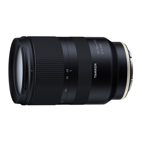
“LUMIX S PRO 70-200 mm F4 O.I.S.”
Focal length f=70 mm to 200 mm
Mount Leica Camera AG L-Mount
F22
23 elements in 17 groups
0.92 m (3.02 feet) to ∞ (from the focus distance reference line)
ⓒ Panasonic Entertainment & Communication Co., Ltd. 2023.
Unauthorized copying and distribution is a violation of law.
Lens construction (1 aspherical lens, 1 UED lens, 3 ED lenses, 1 UHR lens)
Permissible relative humidity 10%RH to 80%RH
-10 ℃ to 40 ℃ (14 ℉ to 104 ℉)
Overall length
Recommended operating
temperature
Mass (Weight) Approx. 985 g (2.17 lb) (excluding the external tripod mount)
Approx. 179 mm (7.0 inch)
(from the tip of the lens to the base side of the lens mount)
77 mm
Aperture type 9 diaphragm blades/Circular aperture diaphragm
S-R70200
Service Training Manual
(Edition of Lens Cleaning) Ver.1.0
Internal use only
TABLE OF CONTENTS
1.1. Introduction
1.2. Overview of Cleaning Components
1.3. Cleaning Service Flowchart
2 Ex
p
loded View
3 Replacement Parts
4 Service Jigs & Tools
5 Disassembly Instructions
5.1. Disassembly Flowchart
5.2. Disassembly Procedure
6 Lens Cleaning
6.1. Cleaning procedures of outside surface of the Lens
6.2. Cleanin
g
p
rocedures of inside surface of the Lens
7 Assembl
y
Instructions
7.1. Assembly Flowchart
7.2. Assembly Procedure
8 Optical Performance Check
8.1. Procedure of Visual Checking
9 Revision History
・ ・ ・ ・ ・ ・ ・ ・ ・ ・ 13
13
・ ・ ・ ・ ・ ・ ・ ・ ・ ・
・ ・ ・ ・ ・ ・ ・ ・ ・ ・ 9
・ ・ ・ ・ ・ ・ ・ ・ ・ ・ 10
・ ・ ・ ・ ・ ・ ・ ・ ・ ・
・ ・ ・ ・ ・ ・ ・ ・ ・ ・
・ ・ ・ ・ ・ ・ ・ ・ ・ ・
8
9
・ ・ ・ ・ ・ ・ ・ ・ ・ ・
8
8
・ ・ ・ ・ ・ ・ ・ ・ ・ ・
4
・ ・ ・ ・ ・ ・ ・ ・ ・ ・ 6
PAGE
1 Service Navigation 1
1
・ ・ ・ ・ ・ ・ ・ ・ ・ ・
・ ・ ・ ・ ・ ・ ・ ・ ・ ・
1
3
・ ・ ・ ・ ・ ・ ・ ・ ・ ・
・ ・ ・ ・ ・ ・ ・ ・ ・ ・
・ ・ ・ ・ ・ ・ ・ ・ ・ ・ 2
・ ・ ・ ・ ・ ・ ・ ・ ・ ・ 5
・ ・ ・ ・ ・ ・ ・ ・ ・ ・ 5
・ ・ ・ ・ ・ ・ ・ ・ ・ ・
3
・ ・ ・ ・ ・ ・ ・ ・ ・ ・ 15

1 Service Navigation
1.1. Introduction
1.2. Overview of Cleaning Components
* This manual contains technical information, which allow service personnel‘s to understand and service this model.
Please place orders using the parts list and not the drawing reference numbers.
Due to conducting lens cleaning with adjustment free, this lens cleaning does not involve the component change and
the parts list contains only limited parts.
Basically we recommend that the lens cleaning requires special facility of cleaning room or cleaning box which met
the standard of class 10,000 or above.
This manual describes the procedures for conducting the lens cleaning of full-frame Interchangeable Lens S-R70200.
This procedures explain to eliminate a debris and dust which invaded into the inside the lens during use.
For lens cleaning it requires to overhaul the lens unit, thus the lens unit disassembles and assembles its components.
The components were the minimum unit which does not have a particular adjustment, only requiring inspection of
visual performance using unique service tools.
External view
Sectional view
Cleanable area
1st Lens Frame Unit
1

1.3. Cleaning Service Flowchart
* In case that the process of Disassembly->Assembly->Inspection repeated for 3 times,
we suppose that the lens was NG and it needs to be replaced by new Lens.
Visual Checking
Disassembly ⇒Cleaning ⇒Assembly
- Begin again after
disassembly/assembly
Check for Internal Dust
Finish
OK
OK
NG
2

2 Exploded View
3 Replacement Parts
・All parts are supplied from PEAC-VSBU.
FILTER RING
RemarksRef.No. Part No. PcsPart Name & Description
221 P197TW0 DECORATION RING
222 P19T030 FRONT RING
This diagram shows exploded view of lens components for lens cleaning.
Only the components applied the parts number are supplied from spare parts.
Other was not eligible.
B221 - B232 0254050 SCREW 12
1
1NOT REUSABLE
1
223 P19T040
221
B225
B224
B221
B222
B223
B226
B227
B228 Alignment Washer
1st Lens Frame Unit
222
223
B231
B232
B229
B230
3

4 Service Jigs & Tools
The following Jigs and Tools are required for checking and servicing this Lens Unit.
Jig Name Jig No. Remarks
Torque Driver RFKZ0542 or RFKZ0456
Rp-Chart L-size SUKZ000034 600mm x 800mm
Rp-Chart M-size SUKZ000035 300mm x 400mm
Lens Cleaning Kit VFK1900BK
Master Body Purchased locally DC-S1R (Panasonic)
Pin Face Wrench Purchased locally Used for Front Ring Disassembly / Assembly
Tweezers Purchased locally Plastic or bamboo (Do not use metal)
Tripod Purchased locally
Illuminometer Purchased locally Set Illumination of chart to 1500±150 lx
Blower Purchased locally
Gloves Purchased locally
Cloth Purchased locally
Clean Box RFKZ0429 This item comes without air pump-filter, purchase
it locally. Model number is Omron ZN-A2502
4

5 Disassembly Instructions
5.1. Disassembly Flowchart
4 1st Lens Frame Unit
1 Decoration Ring
2 Front Ring
3 Filter Ring
5

5.2. Disassembly Procedure
Important Notice:
Perform lens disassembly in the clean room (class 10,000/ Federal Standard 209D) since lens is delicate product
and it dislikes a dust.
When removing the Front Ring, use a Pin Face Wrench.
5.2.1. Removal of Decoration Ring
1. Decoring Unit is sticked on Filter Ring.
2. Put the sheet so that the lens glass is fullty covered.
3. Insert the small flat blade screwdriver to Gap (between Decoring Unit and lens glass), and peel off Decoring Unit gently.
5.2.2. Removal of Front Ring
1. Insert a Pin Face Wrench into the two holes in the Filter Ring.
2. Loosen Front Ring while moving the Pin Face Wrench counterclockwise and remove Filter Ring.
Pin Face Wrench
Front Ring
hole
hole
6

5.2.4. Removal of 1st Lens Frame Unit
2. Remove 6 screws (B) and 1st Lens Frame Unit.
5.2.3. Removal of Filter Ring
1. Remove 6 screws (A) and Filter Ring.
※Be careful when handling 1st Lens Frame Unit.
※If the Alignment Washer is in the position shown below, do not move it from that position.
※Since 1st Lens Frame Unit mounting position needs to be returned to its original position.
(There may be multiple washers.)
1. In order to return the 1st Lens Frame Unit to its original position, mark two places as shown in the figure below.
Alignment Washe
r
Screw (A) x6
Screw (
A
)
Filter Ring
Screw (B) x6
Screw (B)
1st Lens Frame Unit
Marking
7

6 Lens Cleaning
6.1. Cleanin
g
p
rocedures of outside surface of the Lens
1. Blow off the dust on the Lens glass surface with the Blower, gently. (Do not blow strongly.)
2. Wipe out the dirt on the Lens glass surface with Lens Cleaning Kit (VFK1900BK) if necessary.
(Consult the instruction sheet which is included in the Lens Cleaning Kit in details.)
6.2. Cleanin
g
p
rocedures of inside surface of the Lens
1. When removing the each above unit, it has to be proceed inside of satisfied clean level.
(Less than class 10,000 (Federal Standard 209D))
As for clean box, refer to the "4 Service Jigs & Tools", in details.
2. Blow off the dust on the Lens glass surface with the Blower, gently. (Do not blow strongly.)
3. Wipe out the dirt on the Lens glass surface with Lens Cleaning Kit (VFK1900BK) if necessary.
(Consult the instruction sheet which is included in the Lens Cleaning Kit in details.)
【Cleaning Instruction】
Wipe the Lens surface with
cleaning sheet starting
from centre towards to
outside in a circular motion.
Cleanable area
1st Lens Frame Unit
8

7 Assembly Instructions
7.1. Assembl
y
Flowchar
t
4 Decoration Ring
1 1st Lens Frame Unit
2 Filter Ring
3 Front Ring
9

azzzzzzzzzzzzzzzzzzzzzzzzzzzzzzzzzzzzzzzzzzzzzzzzzzz
7.2. Assembly Procedure
Important notice:
When tightening the screw, use a torque driver (RFKZ0542) with specified torque described in each step.
※If the Alignment Washer comes off, put it back in place.
(There may be multiple washers.)
1. Insert 1st Lens Frame Unit according tonthe marking position.
Perform lens disassembly in the clean room (class 10,000/ Federal Standard 209D) since lens is delicate product
and it dislikes a dust.
When Installation the Front Ring, use a Pin Face Wrench.
7.2.1. Installation of 1st Lens Frame Unit
Screw Order
Torque
① → ② → ③ → ④ → ⑤ → ⑥
7.84 ± 1.0 N ・cm
※Be careful when handling 1st Lens Frame Unit.
2. Tighten 6 screws (B) in numerical order by using the torque driver with specified torque.
※Since 1st Lens Frame Unit mounting position needs to be returned to its original position.
Alignment Washer
Screw (B) x6
Screw (B)
1st Lens Frame Unit
Marking
④②
③
①
⑤
⑥
White Line on Lens Unit
10

7.2.2. Installation of Filter Ring
1. Install Filter Ring.
2. Tighten 6 screws (A) in numerical order by using the torque driver with specified torque.
Screw Order
① → ② → ③ → ④ → ⑤ → ⑥
Torque 7.84 ± 1.0 N ・cm
7.2.3. Installation of Front Ring
1. Install Front Ring and Insert a Pin Face Wrench into the two holes in the Filter Ring.
2. Fix Front Ring while moving the Pin Face Wrench clockwise.
Screw (A) x6
Screw (A)
Filter Ring
White Line on Lens Unit and Filter Ring
④
②
③
①
⑤
⑥
Pin Face Wrench
Front Ring
hole
hole
11

1. Insert Decoration Ring so that the center of the LUMIX "M" and the white line on the Lens Unit are aligned.
・Use new one, do not use the one which is removed.
・Double-stick tape sticks to Decoration Ring of the repair part. Remove the old double-stick tape from Front Ring.
2. After installing Decoration Ring, use a soft cloth to press it into place.
7.2.4. Installation of Decoration Ring
Decoration Ring
12

8 Optical Performance Check
8.1. Procedure of Visual Checking
(1)
(2)
(3)
(4)
(5)
(6)
(7)
(8)
- Focus mode : 【S】([AFS])
Mount repaired Lens on master body(DC-S1R).
(valid pixels : 47M pixels image sensor)
Mount master body(DC-S1R) on tripod.
Set the function parameter to below setting.
- Mode dial : A (Aperture-Priority AE Mode)
- Photo style : Standard
- Aspect ratio : 4:3
- Aperture : F4 (Maximum aperture)
Shooting photos to display at an equal magnification on the PC screen.
picture size and horizontal level in TELE end and WIDE end is
full display (camera LCD).
- ISO : 100
- OIS : OFF
- White Balance : AWB
- AF Mode : 1 point
(Focus subject in AF area)
- Metering Mode : Multi
(Focus and measure the subject on the center of the screen)
- Picture Size : L (42M)
- Picture Quality : Fine (JPEG Give priority to the picture quality)
Adjust distance between the camera and RP-Chart so that
Focus on center in the open aperture state 4, take photo by self-timer mode as camera shake does not occur.
As the Shutter Speed of photo taken will be 1/30~1/125, adjust the shooting environment. (Brightness)
(The Shutter Speed is confirmed in the EXIF information)
* It is necessary to change the distance between the camera and
RP-Chart in case of TELE end and WIDE end.
* The standard illuminance on the surface of all the 5 points of
the chart described as shown in the figure with red marking
is 1000±150 lux.
Observation point : Four corners (Angle of view 0.7 and wedge-shaped mark of the outermost)
If it has piece out-of-focus, reassembly again.
By visual check : None piece out-of-focus of resolution number at horizontal and vertical direction.
The balance of resolution number at horizontal and vertical direction is maintained.
illuminance measurement point
Outside of LCD display
Inside of LCD display
RP Chart
Move the Tripod to show expected frame of chart
on the LCD for both TELE end and WIDE end
TELE end : RP-Chart L size
WIDE end : RP-Chart M size
13

RP Chart L-Size 600x800mm
(SUKZ000034)
RP Chart M-Size 300x400mm
(SUKZ000035)
14

9 Revision History
1.0 2023.02.13 ・First Issue
Ver. Date History
15
Table of contents