Magenta 43 Troubleshooting guide

SERVICE MANUAL
&
PARTS LIST
MODEL: Magenta 43
First Edition: 08 July 2020

CONTENTS
WHAT TO DO WHEN....................................................................................................... 1 to 3
SERVICE ACCESS
FACE COVER ........................................................................................................................ 4
FRONT COVER ...................................................................................................................... 5
REAR COVER ........................................................................................................................ 6
MECHANICAL ADJUSTMENT
TOP TENSION ....................................................................................................................... 7
BOBBIN TENSION ................................................................................................................. 8
PRESSER BAR HEIGHT ALIGNMENT................................................................................... 9
NEEDLE SWING .................................................................................................................. 10
NEEDLE DROP ..................................................................................................................... 11
CLEARANCE BETWEEN NEEDLE AND SHUTTLE RACE
(ADJUSTMENT METHOD NO. 1).................................................................................... 12
CLEARANCE BETWEEN NEEDLE AND SHUTTLE RACE
(ADJUSTMENT METHOD NO. 2).................................................................................... 13
FEED DOG HEIGHT ............................................................................................................ 14
NEEDLE BAR HEIGHT ........................................................................................................ 15
NEEDLE TIMING TO SHUTTLE .......................................................................................... 16
BUTTONHOLE FEED BALANCE.......................................................................................... 17
FEED BALANCE ON STRETCH STITCH ............................................................................ 18
BUTTONHOLE FUNCTION ................................................................................................. 19
DISENGAGEMENT OF CAM FOLLOWER .......................................................................... 20
MOTOR BELT TENSION....................................................................................................... 21
WIRING ................................................................................................................................ 22
PARTS LIST.................................................................................................................. 23 to 41

1
PROBLEM CAUSE REMEDY REFERENCE
1. Skipping 1. Needle is not inserted Insert the needle properly.
stitches properly.
2. Needle is bent or worn. Change the needle.
3. Incorrectly threaded. Rethread.
4. Needle or thread are Use the recommended sewing
inappropriate for fabric being needle and thread.
sewn.
5. Sewing on stretch fabric. Use A #11 blue tip needle.
6. Inappropriate needle bar See mechanical adjustment P. 15
height. “Needle bar height.”
7. Inappropriate needle to hook See mechanical adjustment P. 16
timing. “Needle timing to shuttle.”
8. Inappropriate needle to See mechanical adjustment P. 12, 13
shuttle race clearance. “Clearance between needle and
shuttle race.”
2. Fabric not 1. Incorrect feed dog height. See mechanical adjustment P. 14
moving “Feed dog height.”
2. Thread on bottom side of Make sure to bring both needle
fabric is jammed up. and bobbin thread under the foot
when starting sewing.
3. Feed dog teeth are worn. Change the feed dog.
TROUBLESHOOTING

2
PROBLEM CAUSE REMEDY REFERENCE
3. Breaking 1. Initial sewing speed is too fast. Start with medium speed.
upper thread
2. Thread path is incorrect. Use the proper thread path.
3. Needle is bent or dull. Replace with a new needle.
4. Upper thread tension is Adjust upper thread tension P. 7
too strong. correctly.
5. Needle size is inappropriate Use appropriate needle and
for fabric. thread for fabric in use.
6. Needle eye is worn. Change the needle.
7. Needle hole in needle plate is Repair the hole or replace the
worn or burred. needle plate.
4. Breaking 1. Incorrectly thread bobbin case. Thread bobbin case correctly.
bobbin thread
2. Too much thread is around on Adjust the position of stopper.
the bobbin.
3. Lint is stuck inside the hook Clean the hook race.
race.
4. Thread quality is too low. Change to a high quality sewing
thread.
5. Thread is jamming around the Clear out the jamming thread.
bobbin.
6. Bobbin thread tension is too Adjust bobbin thread tension P. 8
strong. correctly.
5. Needle 1. Needle is hitting the needle See mechanical adjustment P. 11
breaks plate. “Needle drop.”
2. Needle is bent or worn. Change the needle.
3. Needle is hitting the hook race. See mechanical adjustment P. 12, 13
“Clearance between needle and
shuttle race.”
4. The fabric moves while the See mechanical adjustment P. 10
needle is piercing it, or the “Needle swing.”
needle zigzags while in fabric.
5. Fabric is being pulled too Guide the fabric gently while
strongly while sewing. sewing.

3
PROBLEM CAUSE REMEDY REFERENCE
6. Noisy 1. Backlash between shuttle hook See mechanical adjustment P. 13
operation gear and lower shaft gear is “Clearance between needle and
too great. shuttle race (NO. 2).”
2. Lower shaft gear is loose. Eliminate the looseness.
3. Inappropriate belt tension. See mechanical adjustment P. 21
“Motor belt tension.”
4. Upper shaft gear is loose. Eliminate the looseness.
5. Not enough oil. Oil all moving parts.
7. Deformation of 1. Inappropriate zigzag See mechanical adjustment P. 10
pattern synchronization. “Needle swing.”
2. Inappropriate disengagement See mechanical adjustment P. 20
of cam follower. “Disengagement of cam follower.”
3. Upper thread tension is too Adjust upper thread tension P. 7
strong. correctly.
4. Inappropriate feed balance. See mechanical adjustment P. 18
"Feed balance on stretch stitch."
4
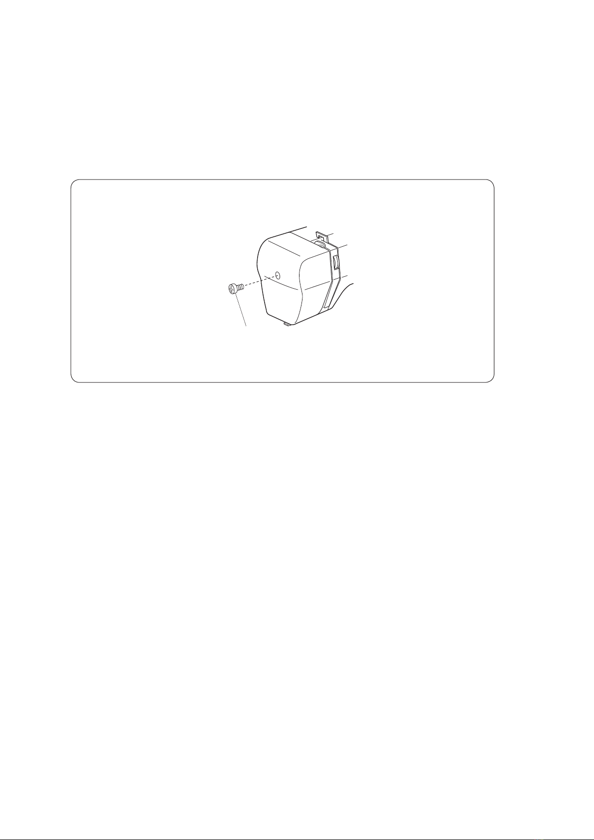
(A)
TO REMOVE
1. Remove the face cover by removing the setscrew (A).
TO ATTACH
2. Follow the above procedure in reverse.
SERVICE ACCESS (1)
FACE COVER
5
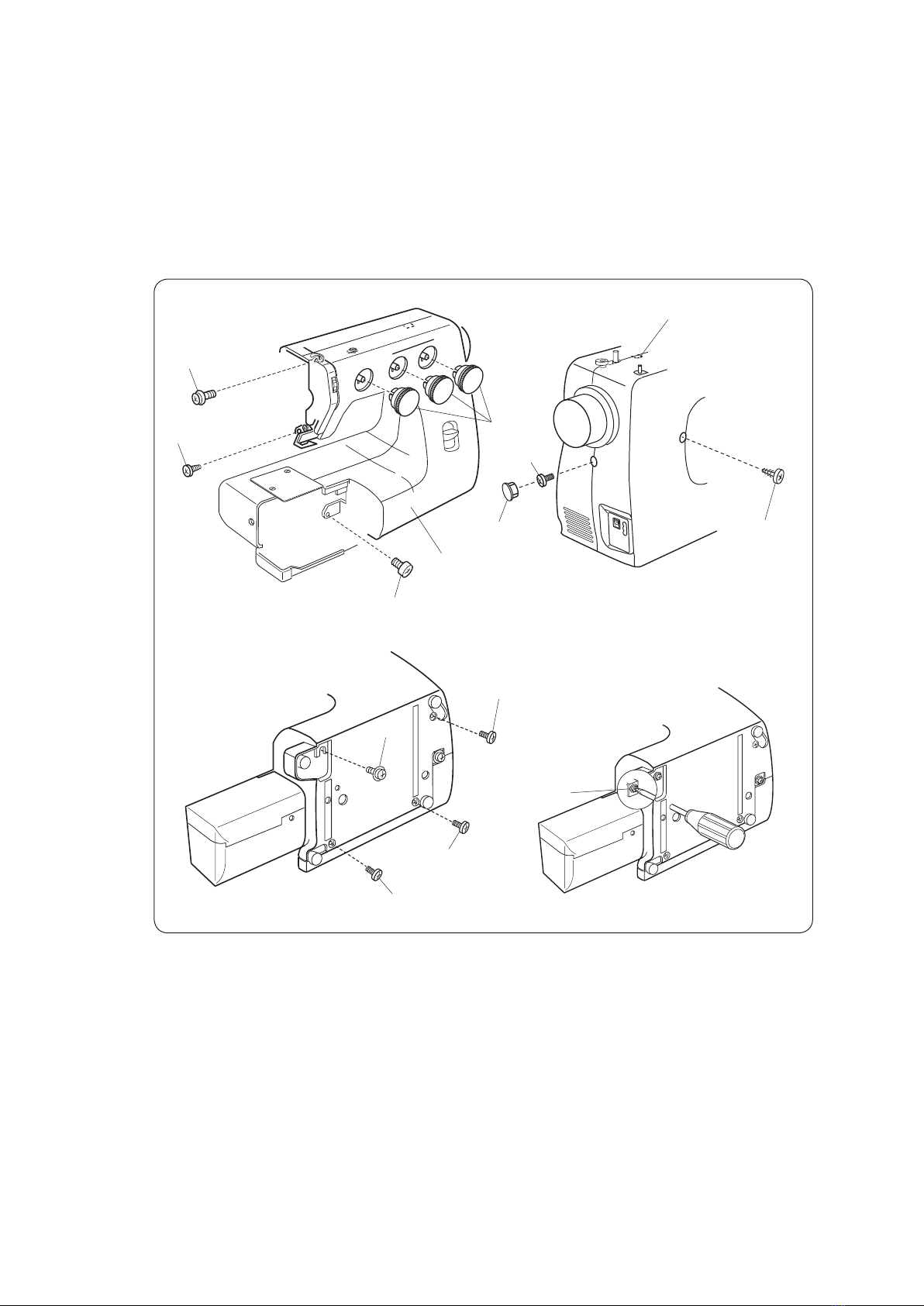
SERVICE ACCESS (1)
FRONT COVER
(D)
(A)
(E)
(G)
Dial
(B)
(F)
(H)
(K)
(C)
(I)
(J)
Cap
Front cover
TO REMOVE
1. Remove the face cover (see page 4).
2. Remove the dials.
3. Loosen the setscrew (A), (B), and (C), and then, remove the front cover by removing
the setscrews (D), (E), (F), (G), (H), (I), and (J).
Note: Unhook the tab (K) from the rear cover when removing the front cover.
TO ATTACH
4. Follow the above procedure in reverse.
6
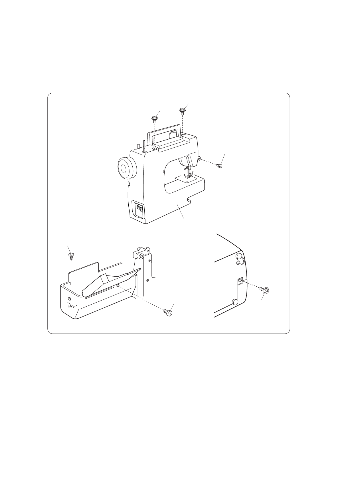
SERVICE ACCESS (4)
REAR COVER
(A)
(B)
(C)
(F)
Rear cover
(D)
(E)
TO REMOVE
1. Remove the face cover and front cover (see pages 4 to 5).
2. Loosen the setscrews (A), (B), and (C), and remove setscrews (D), (E), and (F).
3. Pull up the spool pins. Remove the machine socket. Remove the rear cover clearing
the presser foot lifter from the slit on the cover.
TO ATTACH
4. Follow the above procedure in reverse.
7
MECHANICAL ADJUSTMENT
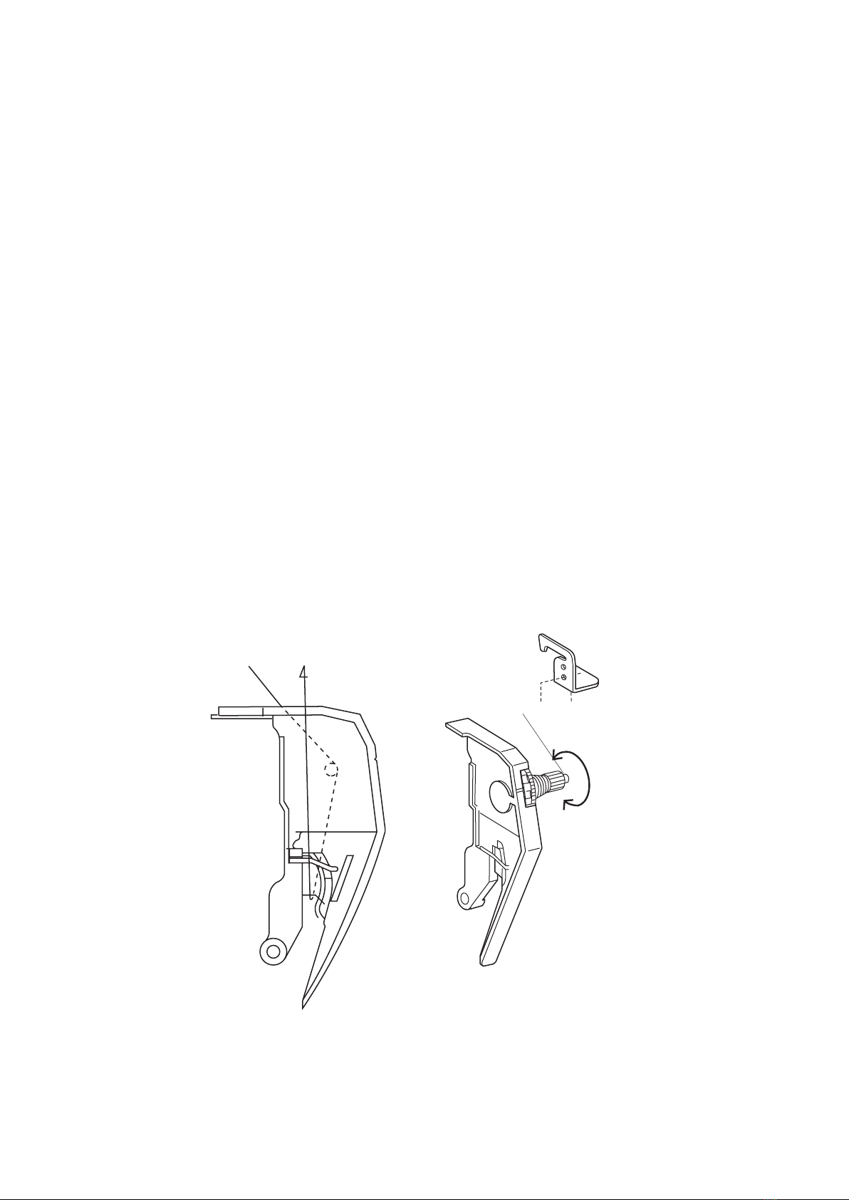
TOP TENSION
TO CHECK:
The standard upper thread tension should be 65 to 95 grams-force when pulling the thread (cotton thread #50)
in the direction of (B) with setting the tension dial at "3". (make sure the foot should be lowered.)
If the tension is out of the standard range, adjust it as follows:
ADJUSTMENT PROCEDURE:
1. Remove the front cover(see page 5).
2. Turn the adjusting screw (C) in the direction of (D) when the upper thread tension is too tight.
Turn the adjusting screw (C) in the direction of (E) when the upper thread tension is too loose.
3. Attach the front cover.
(B)
(C)
(E)
(D)
8
(B)
(E)
(D)
(C)
Cotton thread #50
MECHANICAL ADJUSTMENT
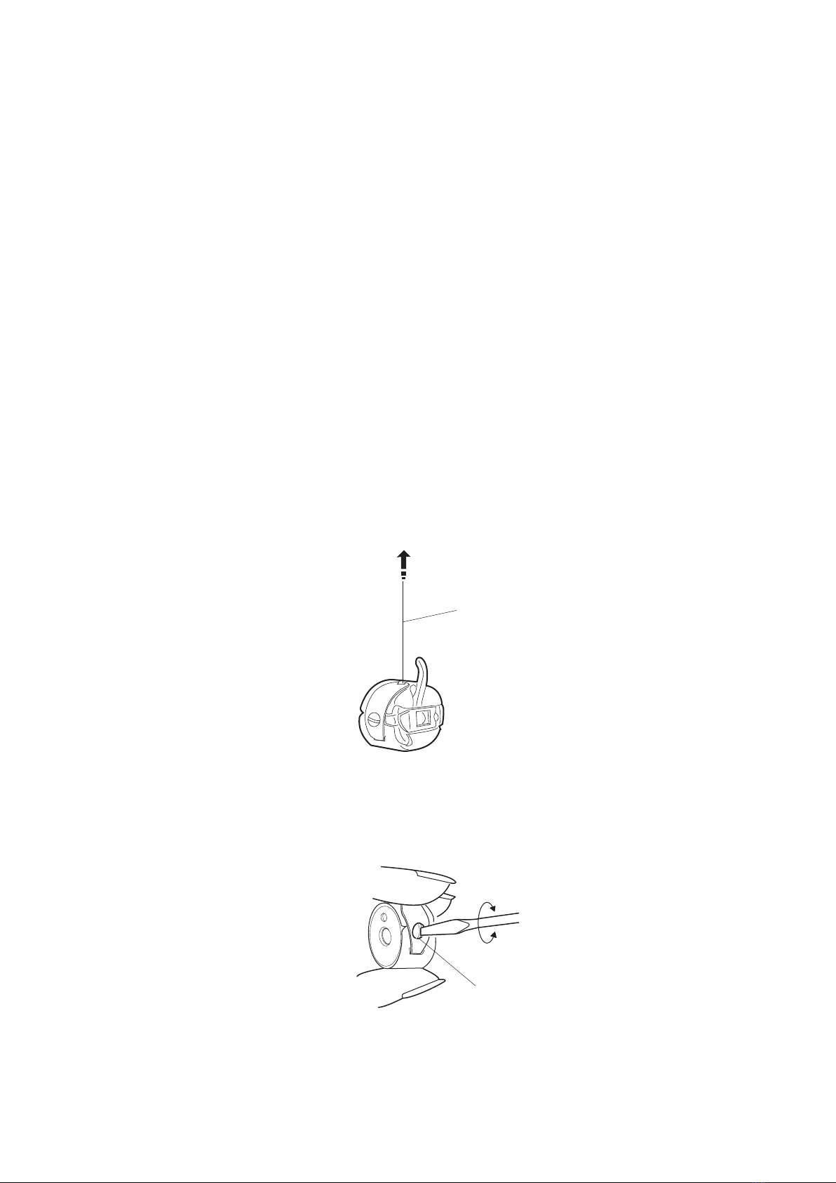
BOBBIN TENSION
TO CHECK:
Set the bobbin in the bobbin case and pass the thread (cotton #50) through the tension spring.
The bobbin thread tension should be 32 to 38 grams-force when pulling the thread in the direction of (B).
If the tension is out of the range, adjust it as follows:
ADJUSTMENT PROCEDURE:
1. Turn the adjusting screw (C) in the direction of (D) when the bobbin thread tension is too tight.
2. Turn the adjusting screw (C) in the direction of (E) when the bobbin thread tension is too loose.
Table of contents


