9
VERTICAL ADJUSTMENT
Apply a crosshatch signal.
Adjust (V-SCORRECTION) to obtain a s-correction picture.
Adjust (V-LINEARITY 50/60) to obtain a linear picture.
Adjust (V-POSITION 50/60) to move the picture at the center.
Adjust (V-SIZE 50/60) to obtain rightful high picture.
ATTN.: These settings should be done with separate test signals with a 50 Hz and a 60 Hz field frequency. These
parameters are stored in separate groups for 50 Hz and 60 Hz and are recalled or set, depending on the field
frequency of the currently received program.
SAFETY PRECAUTION :
Dielectric voltage withstand test :
The following accessible parts should be stressed for a period of one second on each complete appliance before it
leaves the factory.
The test potential voltage not less than 3500V, 50Hz should be applied for 1 second between both blades of the
attachment plug cap. and the following parts :
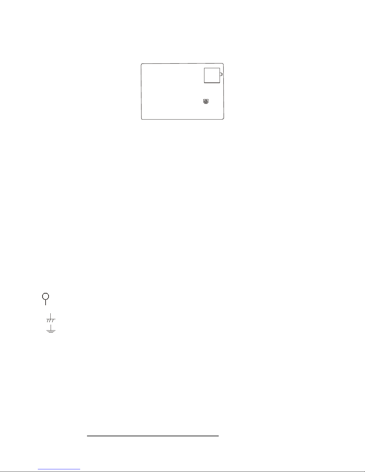
Name of part Locations
1. Antenna Terminal Back Cabinet
2. AV input Terminals Front / Back Cabinet
3. AV output TerminalsBack Cabinet
3. Enclosure Screws Back Cabinet
4. S-Video Sockets Front Cabinet
5. Ext. Speaker Terminals BackCabinet
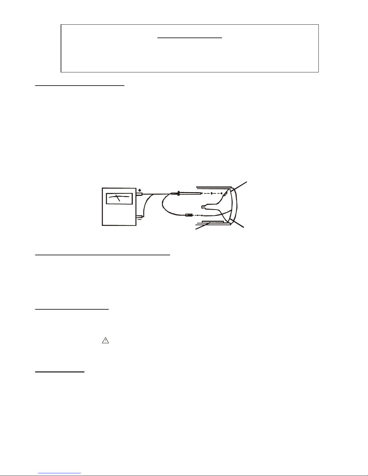
COLOUR PURITY ADJUSTMENT
Note: Before attempting any color purity adjustments, the receiver should be turned on for at least 30 minutes.
(see Figure 8). A few rubber wedges should be available for use whenever necessary during the
process of color purity adjustment.
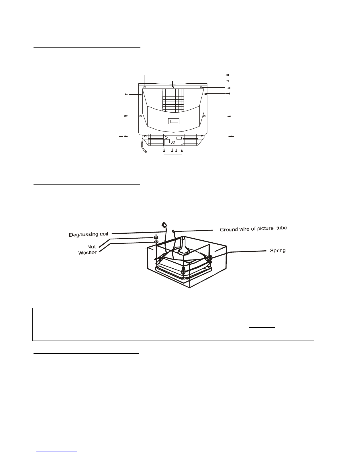
a. Demagnetize the picture tube and cabinet using an external degaussing coil.
b. Turn the CONTRAST and BRIGHTNESS controls to maximum.
c. Adjust RED and BULE bias controls (R-CUT OFF) and (B-CUT OFF) to provide only a green raster.
Advance the GREEN bias control (G-CUT OFF) is necessary.
d. Loosen the clamp screw holding the yoke and slide the yoke and slide the yoke backward to provide
vertical green belt (zone)in the picture screen.
e.Remove the rubber wedges.
f. Rotate and spread the tabs of the purity magnet (See Fig. 9around the neck of the picture tube until the
green belt is in the center of the screen. At the same time center the raster vertically.
g. Move the yoke slowly forward or backward until a uniform green screen is obtained. Tighten the clamp
screw of the yoke temporarily.
h. Check the purity of the red and blue raster by adjusting the(CUT OFF) bias controls.
i. Obtain a white raster, referring to"CRT GREY SCALE ADJUSTMENT (White Balance Adjustment).
j. Proceed with convergence adjustment.
CENTER CONVERGENCE ADJUSTMENT :
Note : Before attempting any convergence adjustments, the receiver should have operated for at least fifteen minutes.
a. Receive crosshatch pattern with a colour bar signal generator.
b. Adjust the BRIGHTNESS and CONTRAST controls fora well defined pattern.
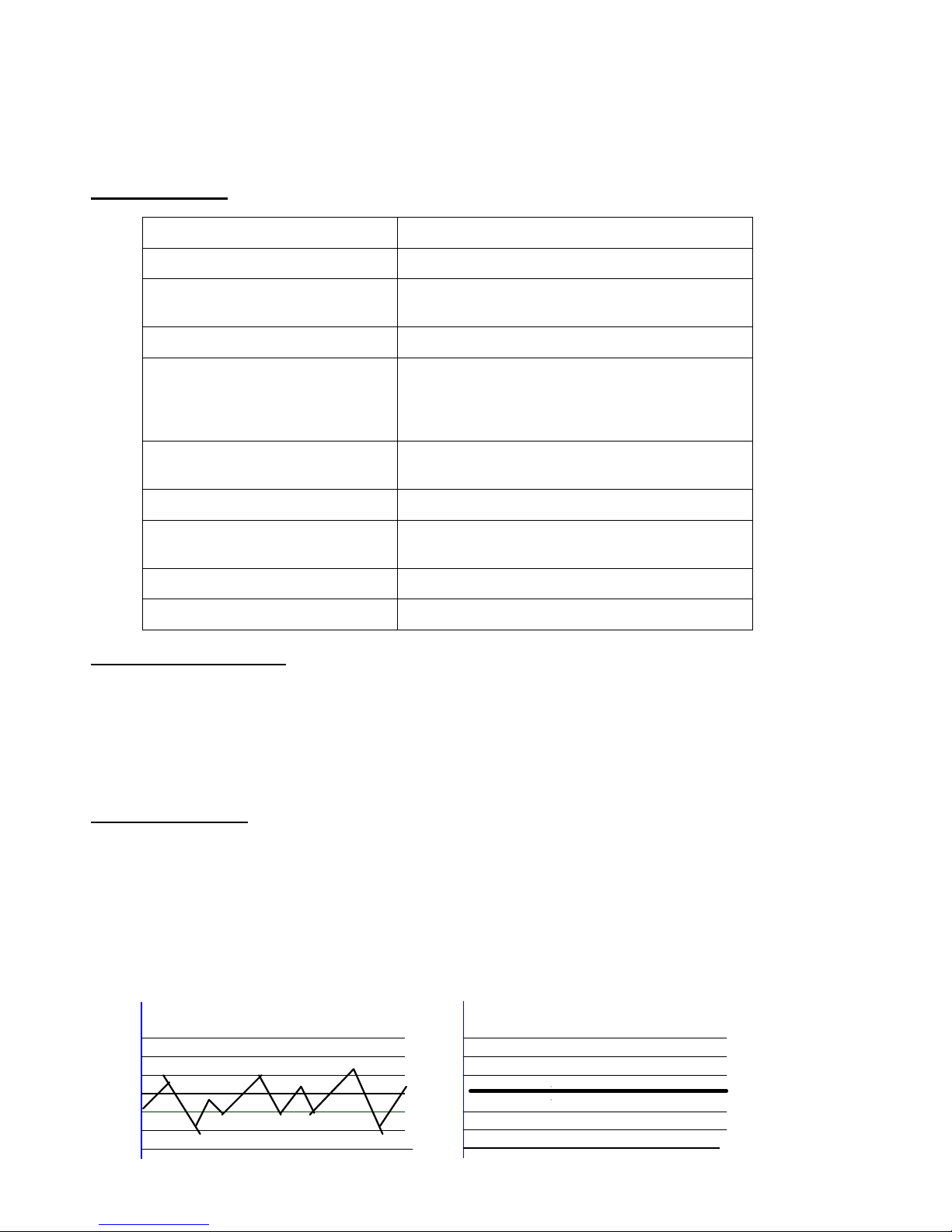
c. Adjust two tabs of the 4-Pole magnets to change the angle between them (See Fig.9) and superimpose red and
blue vertical lines in the center areaof the picture screen (See Fig. 10).
d. Turn both tabs at the same time, keeping their angles constant to superimpose red and blue horizontal lines at
the center of the screen (See Fig. 10).
e. Adjust two tabs of 6-Pole magnets to superimpose red and blue line with green one. Adjusting the angle affects
the vertical lines and rotating both magnets affects the horizontal lines.
f. Repeat adjustmentsc,d,e, keeping in mind red, green and blue movements because 4-Pole magnets and 6-Pole
magnets mutual affection and make dot movement complex.
CIRCUMFERENCE CONVERGENCE ADJUSTMENT :