WARNING
Some illustrations may show the machine without
protective screen or shield. Never use the
machine without these devices.
•
Learn how to stop the machine in emergency
situation. Read this manual and the tractor
manual
• Neve
r let anyone else use this machine if the
person did not read and understand this
manual
•
It is absolutely forbidden to transport persons
or animals on the machine
•
Never let children use this machine
•
Always wear protective equipment for head,
ears, hands
and feet using this machine
• Stay away from the rotor
in use.
• Always wear close-
fitting clothing to avoid to
be snatched by the moving parts or to hang on
•
Clean the worksite from branches, stones or
debris which may be projected and caus
injury or damage
•
Always work on daylight or with good
artificial light
•
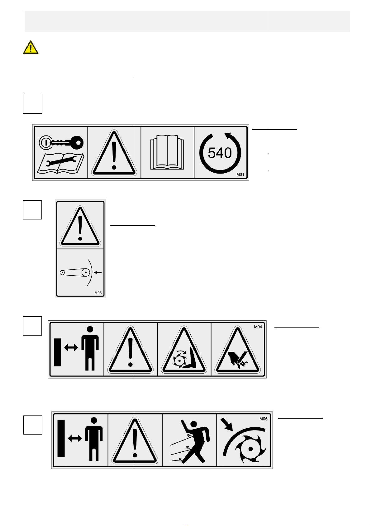
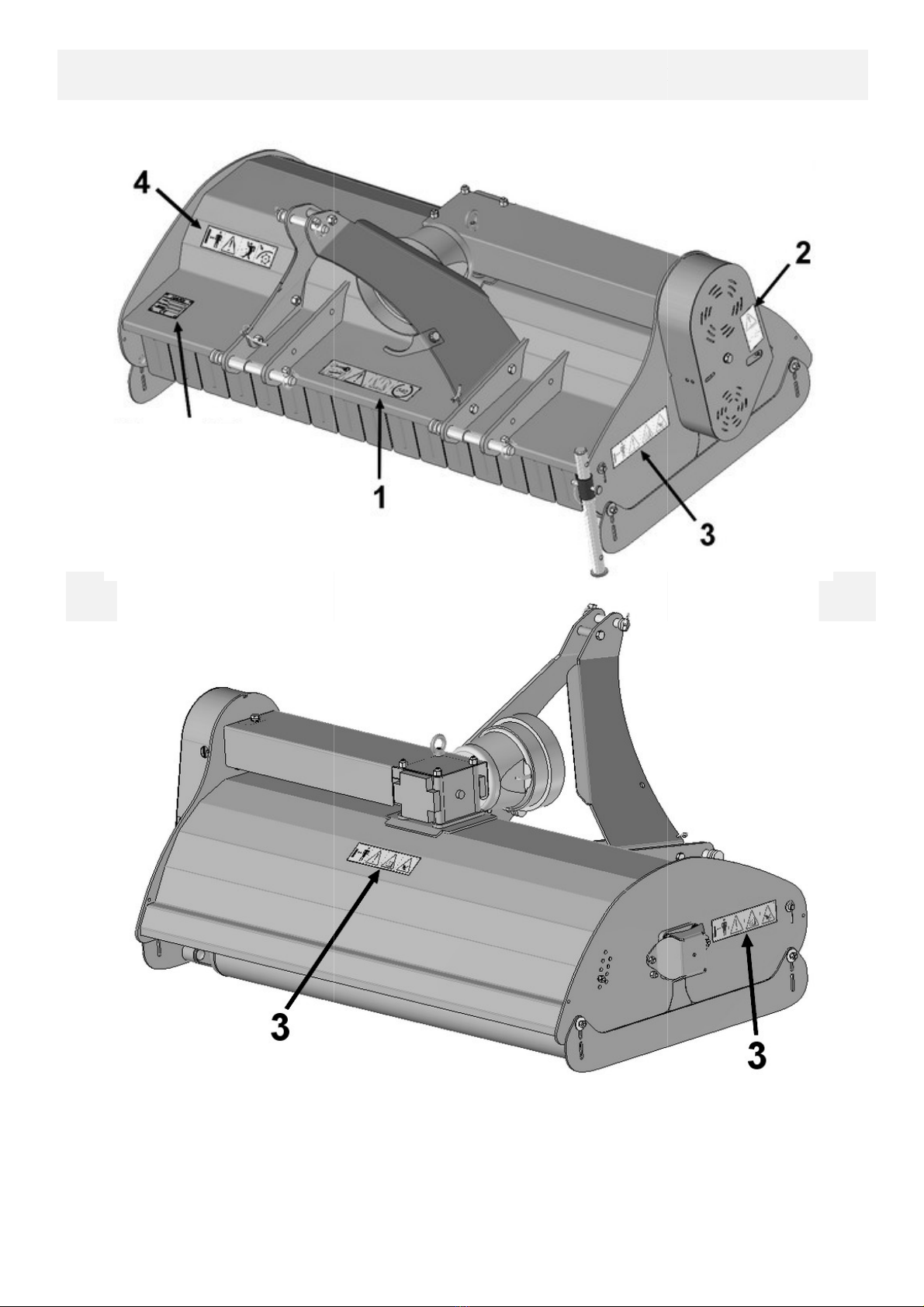
ake sure that the safety stickers are in place
and in good condition
•
Clean the grass and debris accumulations
•
ake sure that the machine is in good
working condition before using it
•
ake sure that all the safety screens, grids
and safety measures are in place and in good
condition
•
Do not use the machine in areas where you
cannot keep safety distance from the persons
or animals to avoid projection injury
• If the tractor has a ROPS Rol
Structure, fasten your seat belt
5
AFETY REGULATIONS
Some illustrations may show the machine without
protective screen or shield. Never use the
Learn how to stop the machine in emergency
situation. Read this manual and the tractor
r let anyone else use this machine if the
person did not read and understand this
It is absolutely forbidden to transport persons
Never let children use this machine
Always wear protective equipment for head,
and feet using this machine
fitting clothing to avoid to
be snatched by the moving parts or to hang on
Clean the worksite from branches, stones or
debris which may be projected and caus
e
Always work on daylight or with good
ake sure that the safety stickers are in place
Clean the grass and debris accumulations
ake sure that the machine is in good
working condition before using it
.
ake sure that all the safety screens, grids
and safety measures are in place and in good
Do not use the machine in areas where you
cannot keep safety distance from the persons
or animals to avoid projection injury
•
ake sure that nobody or anything is behind
•
Do not start or stop the engine abruptly on
slopes
•
Do not use the machine on too big slopes
•
Reduce speed on slopes to avoid a loss of
control
•
Be careful while driving along embankments
or ditches
•
Pay attention to the holes or other area
accidents on undulating terrains
• Stop the
pathways or ways with gravel
•
Disengage the power grip, stop the motor,
apply the han
dbrake and remove the key
before all settings, adjustments, maintenance
or disassembly
•
Never let anyone else to the driver’s cab
during adjustment interventions, maintenance
or disassembly of the machine
•
Check periodically tightening torques of all
fasteners
•
While maneuvering on slope always work up
and down, never across the slope
•
Place the wheels according to the setting
increase stability of the tractor
•
Avoid unstable embankments, rocks and
holes; this can be dangerous when moving
•
obstacles. Contact with power lines causes
•
Activate all the safety equipment
•
Only operate the control panel
correctly seated
•
Check visually hydraulic leaks and missing or
faulty parts.
Repair when necessary before
every manoeuvre
•
Check with the competent authorities that the
linkage complies with the national legislation
ake sure that nobody or anything is behind
Do not start or stop the engine abruptly on
Do not use the machine on too big slopes
Reduce speed on slopes to avoid a loss of
Be careful while driving along embankments
Pay attention to the holes or other area
accidents on undulating terrains
before crossing roads,
pathways or ways with gravel
.
Disengage the power grip, stop the motor,
dbrake and remove the key
before all settings, adjustments, maintenance
Never let anyone else to the driver’s cab
during adjustment interventions, maintenance
or disassembly of the machine
Check periodically tightening torques of all
While maneuvering on slope always work up
and down, never across the slope
.
Place the wheels according to the setting
increase stability of the tractor
.
Avoid unstable embankments, rocks and
holes; this can be dangerous when moving
high-voltage lines and
obstacles. Contact with power lines causes
.
Activate all the safety equipment
Only operate the control panel
when you are
Check visually hydraulic leaks and missing or
Repair when necessary before
Check with the competent authorities that the
linkage complies with the national legislation
.