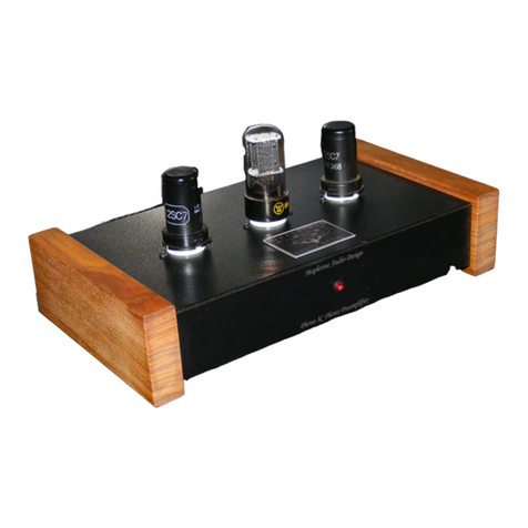
Mapletree Stealth Max User manual
Other Mapletree Amplifier manuals

Mapletree
Mapletree Ultra 4C User manual
Mapletree
Mapletree PS 2D User manual
Mapletree
Mapletree Black Buff User manual
Mapletree
Mapletree Sugarmaple Octal Duo User manual

Mapletree
Mapletree L2X Stereo Line User manual
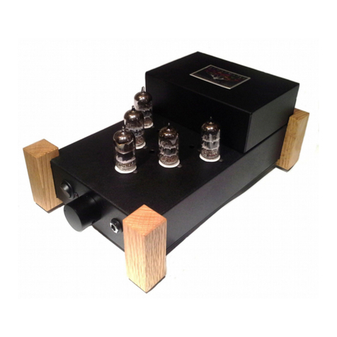
Mapletree
Mapletree Viper OTL User manual
Mapletree
Mapletree Super Stealth + User manual
Mapletree
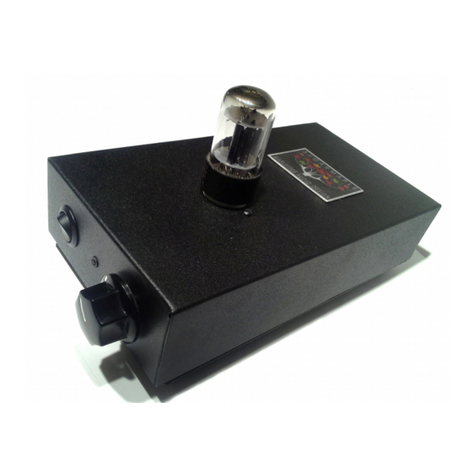
Mapletree SUGARMAPLE Black Buff User manual

Mapletree
Mapletree Ear+ HD II User manual
Mapletree
Mapletree stealth 5 User manual

Mapletree
Mapletree Ear+ HD Super II User manual

Mapletree
Mapletree Phono 3 User manual

Mapletree
Mapletree Line 2B SE User manual

Mapletree
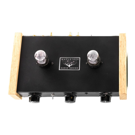
Mapletree Super Stealth User manual
Mapletree
Mapletree Line 2CRM User manual
Mapletree
Mapletree Phono 3E User manual

Mapletree
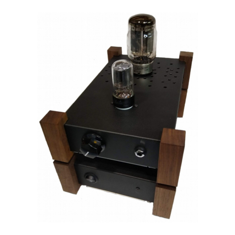
Mapletree Ultra 4B SE User manual
Mapletree
Mapletree Mellow Boy 6SL7 User manual

Mapletree
Mapletree Super Stealth User manual

Mapletree
Mapletree Ear+ HD300 User manual
Popular Amplifier manuals by other brands

Audio Control
Audio Control Architect 100 Installer's guide
Videosystems
Videosystems TA 101 operating instructions
PowerAcoustik
PowerAcoustik A2-200 Introduction manual
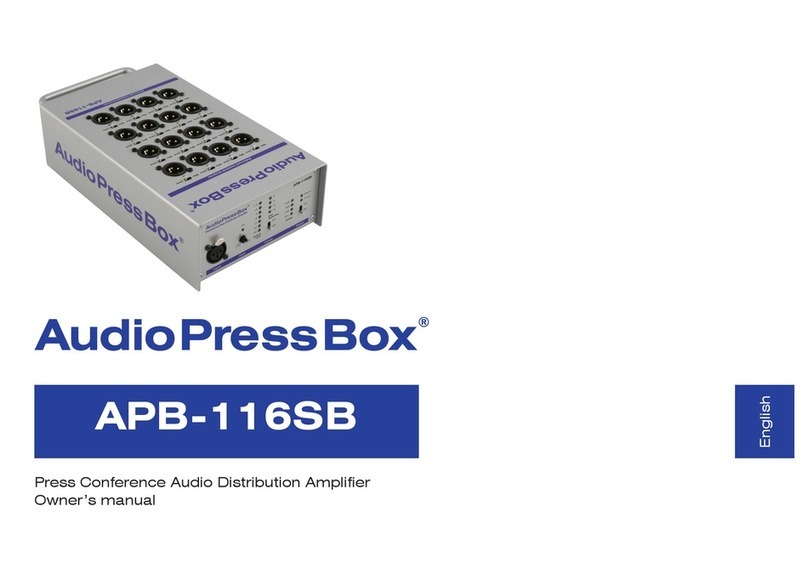
Audio Press Box
Audio Press Box APB-116SB owner's manual

BLACK STAR
BLACK STAR ID:15TVP owner's manual
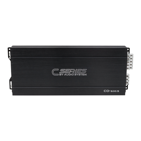
Audiosystem
Audiosystem C Series manual


