Marenius MM-4240 User manual

4/4/2014
MM-4240
4 channel stereo mixer
6 channel recorder
| Manual |
FW 2.1.1
Version 2.00

4/4/2014
Table of contents
1. GENERAL DESCRIPTION 1
2. FRONT PANEL 2
3. BACK PANEL 5
3.1. BALANCED XLR FEMALE /1/4” TRS PIN ASSIGNMENT 7
3.2. BALANCED XLR MALE PIN ASSIGNMENT 7
3.3. 1/4” TRS STEREO PIN ASSIGNMENT 7
3.4. MINI-DIN 4PIN ASSIGNMENT 7
4. POWERING THE MM-4240 8
5. PRIMARY DISPLAY MODE 8
6. QUICK ROUTING INFORMATION 10
7. SOLO 10
8. VIRTUAL TIME CODE SLATE 10
9. MAIN MENU 11
9.1. INPUT CONFIGURATION 12
9.1.1 Limiters 12
9.1.2 Phantom power 12
9.1.3 High pass filter 12
9.1.4 Mid/Side matrix 12
9.2. ANALOG MULTIPLEXING AND NOMINAL ANALOG LEVEL 13
9.2.1 Analog routing busses 13
9.2.1 Nominal analog level 13
9.3. DIGITAL MULTIPLEXING 13
9.3.1 Digital routing busses 13
9.4. RECORD CONFIGURATION 14
9.4.1 Record selection 14
9.4.2 Recording sample rate 14
9.4.3 Recording resolution 14
9.4.4 Time code auto record 14
9.5. GENERAL SETUP 15
9.5.1 File size 15
9.5.2 Device info 15
9.5.3 Set time and date 15
9.5.4 Color settings 15
9.5.5 Misc. settings 16
10. MIXING WITH THE MM-4240 17
10.1. PHANTOM POWER 17
10.2. PRE-GAIN 17
10.3. CHANNEL FADER 17
10.4. LIMITERS 18
10.4.1. Taking maximum advantage of the limiters 18
10.5. MASTER FADER 18
10.6. PANNING 18
10.7. MIXING 18
10.8. TEST TONE 18
10.9. MONITORING 19
10.10. DIGITAL OUTPUTS 19
11. RECORDING WITH THE MM-4240 20
11.1. SD CARDS 20
11.2. RECORDING 21
10.2.1 External record switch (Remote control) 21

4/4/2014
12. PLAYBACK TRACKS 22
12.1. START PLAYBACK 23
12.2. PAUSE PLAYBACK 23
12.3. SKIP TRACK 23
12.4. FAST FORWARD AND FAST REVERSE 23
12.5. STOP PLAYBACK 23
13. TIME CODE AND RTC 24
14. BLOCK DIAGRAMS 25
14.1. CHANNEL INPUT BLOCK DIAGRAM 25
14.2. MASTER OUTPUT BLOCK DIAGRAM 25
14.3. HEADPHONE OUTPUT BLOCK DIAGRAM 25
14.4. MONITOR OUTPUT BLOCK DIAGRAM 25
15. TECHNICAL SPECIFICATIONS 26
APPENDIX A. FIRMWARE UPDATE 27
Package includes
MM-4240 Mixer / Recorder
Mains AC/DC adapter
Mains cable
Interface cable for D1/D2 outputs
User’s Manual

MARENIUS ELEKTRONIKUTVECKLING AB | www.marenius.se | www.marenius.com |www.audiodesign.pro
4/4/2014 MM-4240 User Manual v.2.00 1
1. General description
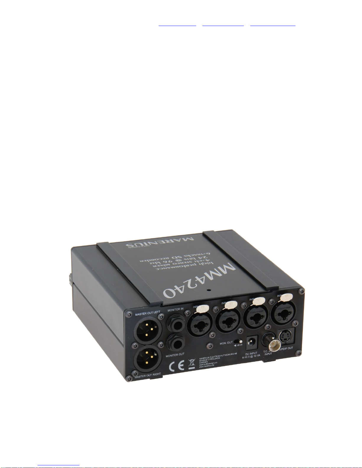
The MM-4240 is a 4 channel stereo mixer and a 6 channel recorder in a very compact format.
The unit has 4 high quality, digitally controlled, THAT Corporation microphone pre-amps.
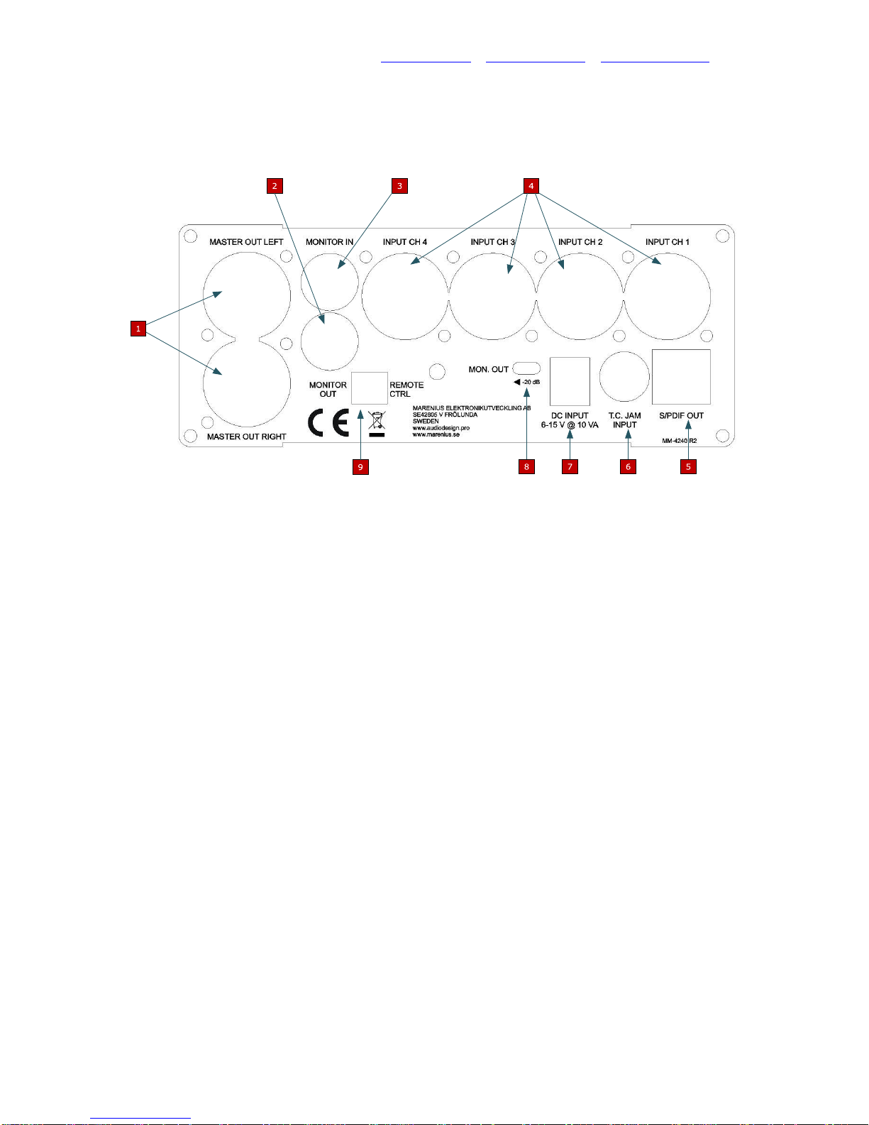
There are 5 stereo output busses, 1 master, 1 monitor, 2 digital and 1 headphone output. The
output busses can be individually assigned to any input pair or the master mix bus.
The unit is able to do mid/side matrix on each input pair.
An extremely wide viewing-angle and very clear OLED display is used for metering, menus and
information.
The MM-4240 has an internal sample rate of 96 kHz and a full 24-bit input-to-output resolution.
The recorder can be setup for other sample rates and resolutions.
The unit has dedicated potentiometers and switches for the most commonly used functions
such as pre-gain, pan, faders, record, test tone, monitoring, etc.
The master faders are combined with ultra-low THD opto-limiters.
Each pre-gain amplifier has a clipping LED allowing the user to set optimum pre-gain for each
scenario.
Linear time code decoding can be used to synchronize the unit to external equipment.
MM-4240 can be powered from standard LR14 (C type) batteries and/or an external 6-15V
power supply. A supercap is used instead of a traditional backup battery for real time clock and
LTC, meaning no internal battery needs to be replaced.
All recorded media is stored on a removable SD card in BWF format.
The MM-4240 is housed in a heavy duty aluminum cabinet.

MARENIUS ELEKTRONIKUTVECKLING AB | www.marenius.se | www.marenius.com |www.audiodesign.pro
4/4/2014 MM-4240 User Manual v.2.00 2
2. Front panel
1.
OLED Display
Displays operation information, settings and menus.
2.
SD Card slot
The SD card slot accepts SDHC and SDXC cards. The card must be placed in the
connector facing downwards. Note: do not use force when inserting or removing card.
3.
Headphone volume / Power switch (outer potentiometer)
Controls the volume for the headphone jack, at full CCW the unit is shut down.
To POWER ON the device turn the knob CW.
3.
Master fader (inner potentiometer)
The master fader gain can be controlled from -∞to +6dB. The current setting is also
shown on the display when changing the gain. The master gain can be switched of when
playing files. The master fader affects the mix-bus.
4.
Headphone jack
The headphone jack accepts headphones with an impedance of 32-600Ω.
Note: high volume can cause damage to your ears; always turn the headphone volume
down before inserting the headphones plug.

MARENIUS ELEKTRONIKUTVECKLING AB | www.marenius.se | www.marenius.com |www.audiodesign.pro
4/4/2014 MM-4240 User Manual v.2.00 3
5.
Menu / Solo navigation switch
The Menu / Solo navigation switch is a five direction switch. To enter the main menu press
the center key, then use up, down, right and left keys to navigate in the menu.
When using up, down, right and left keys outside the menu (not in play mode) each
channel will be sent solo to the headphones.
6.
Status LED
The status led has three colors; each color represents a specific operation mode.
☼ When the LED is red the device is in recording mode.
☼ When the LED is green the device is in play mode or reading from SD card.
☼ When the LED is blue the device output a test tone on all output busses.
7.
Recorder control
The five way navigation switch controls the recorder and the virtual time code slate.
The following switch directions are used:
CENTER
Stop
UP
Start new recording
DOWN
Enter play mode/play/pause; the last file recorded is automatically played
when entering the play mode.
Pressing the button down when playing a file will pause the playback.
Pressing the button down again will resume play.
RIGHT
Next track / Fast forward (only used in play mode)
Move the button to the right to fast forward.
If the MM-4240 is in recording or idle mode a virtual time code slate can
be displayed on the screen using the RIGHT button.
LEFT
Previous track / Fast reverse (only used in play mode)
Move the button to the left to fast reverse. When pressing the LEFT button
in record mode, a file split will occur.
8.
Test tone
Enables the test tone output on all output busses. The test tone switch cannot be activated
when the device is recording or playing tracks.
9.
Info button
Holding down the info button will display quick information about the bus routing and real
time clock. If the info switch is released when playing a file the unit will re-display the time
code information for the current file.

MARENIUS ELEKTRONIKUTVECKLING AB | www.marenius.se | www.marenius.com |www.audiodesign.pro
4/4/2014 MM-4240 User Manual v.2.00 4
10.
Monitor selection switch
The monitor selection switch allows the user to route either the internal associated
headphone output (INT.) or the monitor input (EXT.) to the headphones.
11.
Channel fader (one for each input channel)
The channel faders are used when mixing tracks, adjustable between -∞and +18dB.
When the fader is above 0dB a very low distortion limiter will limit the signal if the
headroom is too low (the limiter has to be enabled in the main menu).
12.
Pan (one for each channel) (outer potentiometer)
Left and right pan for each channel
12.
Pre-gain (one for each channel) (inner potentiometer)
Digitally controlled analog gain control. The gain can be set in 6dB steps, 0-60dB.
13.
Pre-gain CLIP
The CLIP LED is illuminated if the pre-gain stage is clipping.

MARENIUS ELEKTRONIKUTVECKLING AB | www.marenius.se | www.marenius.com |www.audiodesign.pro
4/4/2014 MM-4240 User Manual v.2.00 5
3. Back panel
1.
Master output bus (XLR male connectors)
The master output channels, LEFT and RIGHT.
2.
Monitor output bus (1/4” TRS connector)
The monitor output channels, LEFT and RIGHT.
3.
Monitor input (1/4” TRS connector)
Monitor input, the input can be routed directly to the headphone output from the front panel
monitor switch.
4.
Input channels (XLR female / 1/4” TRS connector)
Four input channels for microphone or line level input.
5.
Digital output busses (2 stereo pairs) (mini-DIN 4 connector)
Two standard S/PDIF output streams. The MM-4240 is shipped with a mini-DIN to 2xBNC
converter cable. The output voltage is set accordingly to the AES3-ID standard, if the
output is connected to an AES3 digital input a voltage level converter may be needed. The
outputs are transformer coupled.
6.
Linear time code input (BNC connector)
The time code input accepts standard linear time code, all frame rates are supported.

MARENIUS ELEKTRONIKUTVECKLING AB | www.marenius.se | www.marenius.com |www.audiodesign.pro
4/4/2014 MM-4240 User Manual v.2.00 6
7.
External power input
An external power source may be connected to the unit. The voltage level must be
between 6V and 15V. The power supply shall be able to source at least 2A for handling
current transients drawn by the unit.
The center pin of the connector is positive supply.
Note: voltage levels above 15V will damage the unit.
8.
Monitor output attenuation pad.
The monitor output may be padded -20dB for connection to low level inputs of e.g.
cameras.
9.
Remote control
The remote control input can be used to connect an external record switch. When the
switch is closed the MM-4240 is recording until the switch is opened.

MARENIUS ELEKTRONIKUTVECKLING AB | www.marenius.se | www.marenius.com |www.audiodesign.pro
4/4/2014 MM-4240 User Manual v.2.00 7
3.1. Balanced XLR female / 1/4” TRS pin assignment
Balanced analog audio input
Connector type
XLR/TRS Combo
Ground
Pin 1, Sleeve
Hot
Pin 2, Tip
Cold
Pin 3, Ring
3.2. Balanced XLR male pin assignment
Balanced analog audio output
Connector type
XLR
Ground
Pin 1
Hot
Pin 2
Cold
Pin 3
3.3. 1/4” TRS stereo pin assignment
Unbalanced analog audio input/output
Connector type
TRS
Ground
Sleeve
Left
Tip
Right
Ring
3.4. Mini-DIN 4 pin assignment
Digital audio output
Connector type
Mini-DIN 4
1
BUS1-
2
BUS2-
3
BUS1+
4
BUS2+

MARENIUS ELEKTRONIKUTVECKLING AB | www.marenius.se | www.marenius.com |www.audiodesign.pro
4/4/2014 MM-4240 User Manual v.2.00 8
4. Powering the MM-4240
The MM-4240 can be powered from an external power supply or six standard LR14 (C type)
batteries. Both NiMH and alkaline batteries can be used.
The batteries shall be placed in the battery holder as the label on the battery cover describes.
The battery chemistry shall be set in the main menu to allow the unit to display the correct
battery level.
The MM-4240 can be powered from an external power supply of 6V-15V; the external power
supply can be a mains adapter, batteries or any power supply that is able to delivery at least 2A
of current. Even if the MM-4240 doesn’t draw 2A the power supply must be able to handle load
transients.
The internal batteries are disconnected from the unit when an external power supply is
connected to the unit. Therefore it is very important that the voltage level of the external power
supply doesn’t drop below 6V.
When a valid external power supply and or six LR14 batteries has been connected to the unit
turn the headphone potentiometer clockwise to power on the unit.
5. Primary display mode
When the MM-4240 is powered up the primary display mode is entered. The unit displays
meters, recording settings, channel settings, time code, power information and SD card usage.
The image below shows the primary display mode.

MARENIUS ELEKTRONIKUTVECKLING AB | www.marenius.se | www.marenius.com |www.audiodesign.pro
4/4/2014 MM-4240 User Manual v.2.00 9
1.
Current recording sample rate
The recording sample rate can be changed between 48kHz and 96kHz. The internal
sample rate of the unit is always 96kHz. It is recommended to record at 96kHz to minimize
recording distortion since a sample rate conversion always adds distortion to the converted
signal.
2.
Current recording bit depth
The recording bit depth can be changed between 16-bit and 24-bit (stored as 32-bit).
3.
Number of recording channels
Display the current number of channels that are enabled for recording.
4.
SD Card usage
Shows information about the SD card usage in percent. If no card is inserted into the SD
card slot the value is “---“.
5.
External power
The power symbol is lit when an external power source is attached to the unit.
6.
Battery level
Displays current internal battery level. The symbol is filled with green or red depending on
the current level. If the symbol is flashing, replace the batteries as soon as possible. The
MM-4240 will only run for about 10 minutes when the battery symbol is flashing.
Note: For a true display of the battery level, the battery chemistry must be set.
7.
Channel meter rows
The meter row shows the current channel input level and the “CHx” indicator. If the limiter
for the channel is enabled and the limiter is active a “LIM” symbol appears to the right of
the meter. If the limiter for the channel is disabled a “CLP” symbol is shown if the level is
too high. The clip indication shown in the display doesn’t include pre-gain clip. This is
shown by the CLIP LED on the front panel.
8.
Channel information rows
Below each channel the current channel setting is shown. The following symbols can
appear in the channel information rows:
“xdB”, Current pre-gain I dB
“LIM”, Limiter enabled
“PH”, 48V phantom power enabled
“HPF”, High pass filter enable
“MID”, MS matrix enable, mid channel
“SIDE”, MS matrix enable, side channel
9.
Record/test tone field
If the MM-4240 is recording a “REC” symbol is lit in the field. If the test tone is enabled a
“1kHz” symbol is flashing in the field.
10.
Time code display area
The time code display area can show time code with three or four numbers. If an external
time code generator is connected to the MM-4240 the time code is displayed with four
numbers otherwise only three numbers are displayed. If the MM-4240 is jam synchronized
and the internal time code counter is valid an “S” is displayed to the right of the time code.
When recording the display area shows the elapsed recording time.
11.
Left and right mix level
The meters display the level of the stereo mix. A “CLP” symbol may appear to the right of
the meter if the mix is clipped.

MARENIUS ELEKTRONIKUTVECKLING AB | www.marenius.se | www.marenius.com |www.audiodesign.pro
4/4/2014 MM-4240 User Manual v.2.00 10
6. Quick routing information
The MM-4240 is equipped with an “INFO” button allowing the user to quickly view routing
information. The quick info screen displays routing for all five output busses, channels enabled
for recording and real time clock. The quick info also displays the number of files on the SD
card, SD card usage in percent and remaining recording time at current configuration. The MM-
4240 automatically switched between card usage and remaining recording time when the
“INFO” button is hold. In play mode the remaining recording time will not be displayed.
If the device is recording, the current internal buffer usage is displayed in the quick information
screen. This is useful to get a hint of the speed of the SD card; if the buffer level continuously
fills to near 100% the SD card is alarmingly slow for the current record setup.
The following routing information is shown when holding down the quick info button:
MASTER OUT
MONITOR OUT
HEADPHONE OUT
DIGITAL OUT 1
DIGITAL OUT 2
RECORD (Not shown when playback is activated)
BUFFER LEVEL (In record mode)
FILES (In idle- and play- mode)
REMAINING RECORD TIME (In idle mode)
7. Solo
The solo function is shared with the menu navigator button.
To solo one of the input channels to the headphone output use the UP- (Channel 1), RIGHT-
(Channel 2), DOWN- (channel 3) or LEFT-button (Channel 4).
When the channel is sent monophonic to the headphone channel the “CHx” indicator is
highlighted.
The solo function is only available in primary display mode and in recording mode.
See “Recording with the MM-4240” for color coding of “CHx” indicator.
8. Virtual time code slate
The MM-4240 has a virtual time code slate function. The feature is useful when recording video
with cameras that doesn’t have a time code function.
When the mixer is in recording- or idle- mode the right button of the recorder navigation key can
be pressed. The virtual time code slate will be displayed for 30 seconds allowing the user to film
the mixer during this time. To manually exit the feature press the right button again.
When filming the MM-4240 the LED will flash with one FPS + 1 millisecond if external time code
is connected. If external time code is not present on the time code input connector the LED will
flash with 24FPS. The flash occurs exactly when the frame counter becomes zero. When the
flash occurs the counter in the time code counter in the display will have some delay since it is
impossible to display time code before it has been read. In the post process the flash can easily
be found, if the flash is active for more than one frame the first frame showing the flash shall be
used as time reference.

MARENIUS ELEKTRONIKUTVECKLING AB | www.marenius.se | www.marenius.com |www.audiodesign.pro
4/4/2014 MM-4240 User Manual v.2.00 11
9. Main menu
Secondary functions are accessible through the main menu. To enter the main menu press the
center button of “MENU” switch. To navigate through the menu use the MENU navigation
switch. The main menu structure is shown in the illustration below. The menu will automatically
return one step every 15 second until the general screen has been reached.
A quick exit from the menu can be done using the “INFO” button.

MARENIUS ELEKTRONIKUTVECKLING AB | www.marenius.se | www.marenius.com |www.audiodesign.pro
4/4/2014 MM-4240 User Manual v.2.00 12
9.1. Input configuration
The input configuration menu controls all four input channels. The table below illustrates the
input configuration menu.
CH (Channel)
1
2
3
4
LIM (Limiter)
PH (48V)
HPF (High pass)
M/S (MS Matrix)
The navigation switch is used to navigate through the table. To enable or disable a function on
a channel press the center button on the navigation switch.
9.1.1 Limiters
The MM-4240 is fitted with four ultra-low THD opto-limiters. To enable a limiter on a channel
press the center button, then an “X” is displayed for the selected channel. The limiters are only
connected to the channel faders.
These limiters are completely analog for perfection in sound quality.
9.1.2 Phantom power
To enable 48V phantom power on the marked channel, press the center button. If the phantom
power is disabled on all channels the phantom power circuitry is powered down to save power.
When the phantom power circuitry is powered up there may be a small pop on the input
channel. The phantom power circuitry is able to source 10mA to each input channel;
however, maximizing the phantom power output current will drain the batteries quickly if
operating from the internal batteries.
9.1.3 High pass filter
An analog secondary order high pass filter may be assigned to each input channel. The high
pass filter is optimized to remove some of the wind noise that can appear when mixing
outdoors. The cutoff frequency is fixed to 200Hz.
9.1.4 Mid/Side matrix
A mid/side matrix (M/S) can be calculated on each input pair (1 & 2 or 3 & 4) where the odd
channel is used as mid signal and the even channel is used as side signal. A typical mid side
setup is illustrated below.

MARENIUS ELEKTRONIKUTVECKLING AB | www.marenius.se | www.marenius.com |www.audiodesign.pro
4/4/2014 MM-4240 User Manual v.2.00 13
9.2. Analog multiplexing and nominal analog level
Each analog output bus can be assigned to any stereo pair represented on the input or mixing
bus. The table below shows the analog output multiplexing possibilities.
CH (Channel)
R+L
1+2
3+4
N.LV.
MST (Master)
MON (Monitor)
HP (Headphone)
The navigation switch is used to navigate through the table. To select/change a setting press
the center button on the navigation switch.
9.2.1 Analog routing busses
The routing busses can be paired in the follow busses where each bus consists of two
channels:
1. MST Master bus (output bus)
2. MON Monitor out bus (output bus)
3. HP Headphone bus (output bus)
4. R+L Right and Left mix (input bus)
5. 1+2 Channel 1 and channel 2 input (After pre-gain and channel fader) (input bus)
6. 3+4 Channel 3 and channel 4 input (After pre-gain and channel fader) (input bus)
All analog output busses can be coupled to any of the input busses through the table shown
above.
9.2.1 Nominal analog level
The master and monitor output nominal level (N.LV.) can be selected as +4dBu, 0dBu or
-10dBv depending on which kind of equipment the output bus shall be connected to. Use the
center button to step through the different levels. Note: setting the level to 0dBu or -10dBv
slightly decreases the dynamic range of the output signal since the attenuation is digital.
9.3. Digital multiplexing
Each digital output bus can be assigned with any stereo pair represented on the input or mixing
bus. The table below shows the digital output multiplexing possibilities.
CH (Channel)
R+L
1+2
3+4
D1 (Digital 1)
D2 (Digital 2)
The navigation switch is used to navigate through the table. To select/change a setting press
the center button on the navigation switch.
9.3.1 Digital routing busses
The routing busses can be paired in the follow busses where each bus consists of two
channels:
1. D1 Digital 1 output bus (output bus)
2. D2 Digital 2 output bus (output bus)
3. R+L Master output bus (input bus)
4. 1+2 Channel 1 and channel 2 input (After pre-gain and channel fader) (input bus)
5. 3+4 Channel 3 and channel 4 input (After pre-gain and channel fader) (input bus)
All digital output busses can be coupled to any of the input busses through the table shown
above.

MARENIUS ELEKTRONIKUTVECKLING AB | www.marenius.se | www.marenius.com |www.audiodesign.pro
4/4/2014 MM-4240 User Manual v.2.00 14
9.4. Record configuration
The record configuration menu sets up all recording parameters except the file size which is
handled under the general setup menu. This menu option is not available while the MM-4240 is
recording.
The sample rate and resolution only affects the recording and not the internal processing of the
MM-4240.
9.4.1 Record selection
The table shown in recording configuration sets the channels to be recorded. The user can
select any combination of “1+2”, “3+4” and “R+L” where “1+2” and “3+4” are input channels
1,2,3 and 4 after the pre-gain and the channel fader, and “R+L” is the stereo mix.
9.4.2 Recording sample rate
The recording sample rate can be set to 48 kHz or 96 kHz. When using 48 kHz recording
sample rate the MM-4240 down-samples the internal 96 kHz signal. This adds a slight distortion
to the recorded signal since all down sampling creates new samples from the original samples.
The MM-4240 uses a three point interpolation algorithm for down-sampling.
9.4.3 Recording resolution
The recording resolution can be set to 16bit or 24bit. When using 24bit resolution the MM-4240
will save the samples in 32bit format. When using 16bit recording resolution the MM-4240 will
use a truncation algorithm for lowering the resolution.
9.4.4 Time code auto record
The MM-4240 is able to start and stop recording depending on a time code signal. If the feature
is turned off the device will function as a regular recorder. This option has two choices, time
code detection (DET) and time code running (RUN).
The time code auto record on detection (DET) will automatically start a new recording if a valid
time code stream is detected on the time code input. The MM-4240 will record as long as the
time code signal is represented on the time code input regardless of the record button.
The time code auto record on running (RUN) will automatically start a new recording if a valid
time code stream is running on the time code input. The MM-4240 will record as long as the
time code signal is running on the time code input regardless of the record button. If the time
code is paused the recording will stop. If the time code is resumed a new track will be recorded.

MARENIUS ELEKTRONIKUTVECKLING AB | www.marenius.se | www.marenius.com |www.audiodesign.pro
4/4/2014 MM-4240 User Manual v.2.00 15
9.5. General setup
The general setup menu handles various settings of the MM-4240
9.5.1 File size
This option sets the recording file size. The user is able to choose between:
128MB
265MB
512MB
1GB
2GB
4GB
The MM-4240 will split files sample-accurate, so files joined together in post-production will be
seamless. However if the SD card is to slow this will fail since the internal buffer will overflow.
To avoid overflow the file size may be decreased. This requires some trial and error on the
used SD card to find the limits.
9.5.2 Device info
This screen shows the following information about the MM-4240:
Unique serial number
Firmware version
Battery voltage
Maximum recording buffer usage since last power on
9.5.3 Set time and date
The internal real time clock can be set with this menu option. Use the five way navigation key to
setup the clock. To change a value, unlock it with the center button.
9.5.4 Color settings
The user is able to change the colors used in the menu and the colors used in the channel
information rows. The available colors are:
PURPLE
RED
GREEN
BLUE
DARK RED
YELLOW
PINK

MARENIUS ELEKTRONIKUTVECKLING AB | www.marenius.se | www.marenius.com |www.audiodesign.pro
4/4/2014 MM-4240 User Manual v.2.00 16
9.5.5 Misc. settings
The misc. settings menu sets up the battery chemistry, the play attenuator and time code
correction.
The battery chemistry must be set to the battery chemistry used for a correct battery level
meter. The choices are
Alkaline
NiMH
Other batteries may be used as long as the voltage stays between 5V and 10V; however the
battery level indicator will be incorrect.
The play attenuator can be enabled or disabled. When the attenuator is enabled the master
attenuator potentiometer can be used to control the playback volume between -∞dB and +6dB.
The playback attenuator can be disabled to avoid conflict with the master attenuator when
changing between playback mode and normal mode. When the playback attenuator is disabled
the playback level is equal to the level of the file.
The time code correction can be adjusted ±1 frame for 24FPS, 25FPS, 30FPS and 29.97FPS.
The adjustment adds or subtracts one frame from the BWF header. When the time code
correction is set to 0 frames the recording will start when the frame counter switches to zero,
however; some setups use the time code after it has been read. In that case the time code will
be one frame late.
The “Misc” menu also includes a firmware update option, for information about the firmware
update procedure see appendix “Appendix A. Firmware update”.

MARENIUS ELEKTRONIKUTVECKLING AB | www.marenius.se | www.marenius.com |www.audiodesign.pro
4/4/2014 MM-4240 User Manual v.2.00 17
10. Mixing with the MM-4240
Mixing audio with the MM-4240 is very straight forward, however there are some details that
require attention to avoid clipping and produce mixes with high quality sound.
10.1. Phantom power
The phantom power can be enabled for each input channel if needed. The phantom power shall
not be enabled unless required since it will draw excessive power and add a small amount of
noise to the signal. The following parameters apply to the phantom power circuitry:
Phantom power parameters
Maximum total phantom power current:
40mA
Maximum phantom power on each channel
10mA
Phantom power series resistance
6.8kΩ
The phantom power circuitry uses a step up regulator. It will use more current from the input
than drawn on the output.
The equation below can be used to calculate how much battery current is need to source
phantom power (Iph = phantom current, BV = Battery voltage):
For example, to source 10mA of phantom current ~100mA of battery current is needed if the
battery voltage is 9V.
The phantom power is ramped up so there will be up to 5 seconds delay before the phantom
power is available on the input connector.
10.2. Pre-gain
The pre-gain knob is the inner knob of the lower concentric potentiometers. The potentiometers
are stepped. Eleven 6dB steps allow a maximum pre-gain of 60dB. A clip LED for each pre-gain
is located next to the knob. The pre-gain for each channel is also shown in the OLED display as
the figure above illustrates. For optimal performance the pre-gain shall be set as close to the
clipping level as possible.
10.3. Channel fader
Each channel has a fader for controlling the mix. The fader is adjustable between -∞ and +18dB
(min.). The fader has been optimized for controlling the level from -6dB to +18dB. As for the
pre-gain, the channel fader shall be set as close to the clipping level as possible for optimal
performance.
Table of contents
Other Marenius Music Mixer manuals