Marlec Rutland 1200 Owner's manual

Doc No: SM-351 Iss A 18.07.16
MarlecEngCoLtd
Rutland Remote Display
-Model 1200
Installation and Operation

Doc No: SM-351 Iss A 18.07.16
MarlecEngCoLtd
Technical Specifications
Dimensions
Surface Mount: 125x75x50mm Weight: 203g
Recess Mount: 125x75x9mm Weight: 132g Recess Mount Cut Out: 100x62mm
Power Supply: via 3m serial cable supplied. Longer cables available at www.marlec.co.uk
Introduction
The Rutland Remote 1200 Model is designed for use with the Rutland 1200 Wind Turbine. It enables
convenient viewing of the wind generator and PV solar panel charge currents, power, battery Voltages,
charging status and accumulated ampere hours of charge to the batteries. It connects to the Rutland
1200 Hybrid Controller via a serial cable and mounting is optional between surface and recessed.
Exploded View
1

Doc No: SM-351 Iss A 18.07.16
MarlecEngCoLtd
UP DOWN ENTER
Mounting—2 Options are Available
Surface mount using the supplied back box. Fix the back box using suitable screws and fit the display
using screws supplied.
Recess mount by discarding the back box and mount directly to a panel with a 100mm x 62mm cut out,
using suitable screws .
Fit the screw caps supplied to finish.
Electrical Connection
The power supply for the unit is provided from the WG1200 controller via the serial data cable
supplied. Locate the RJ11 sockets on the controller and display unit to connect the 2 devices. The
screen will power up. Press any button to illuminate the backlight.
Note: In late 2016 a wireless Bluetooth kit will be available which will plug in at each end in place of the
cable. The Remote Display will require a local 12/24v dc power supply which is connected via the
terminal block mounted on the pcb. Important: Do not connect a local power supply to these
terminals if the remote is connected to the 1200 Controller via the serial cable.
2

Doc No: SM-351 Iss A 18.07.16
MarlecEngCoLtd
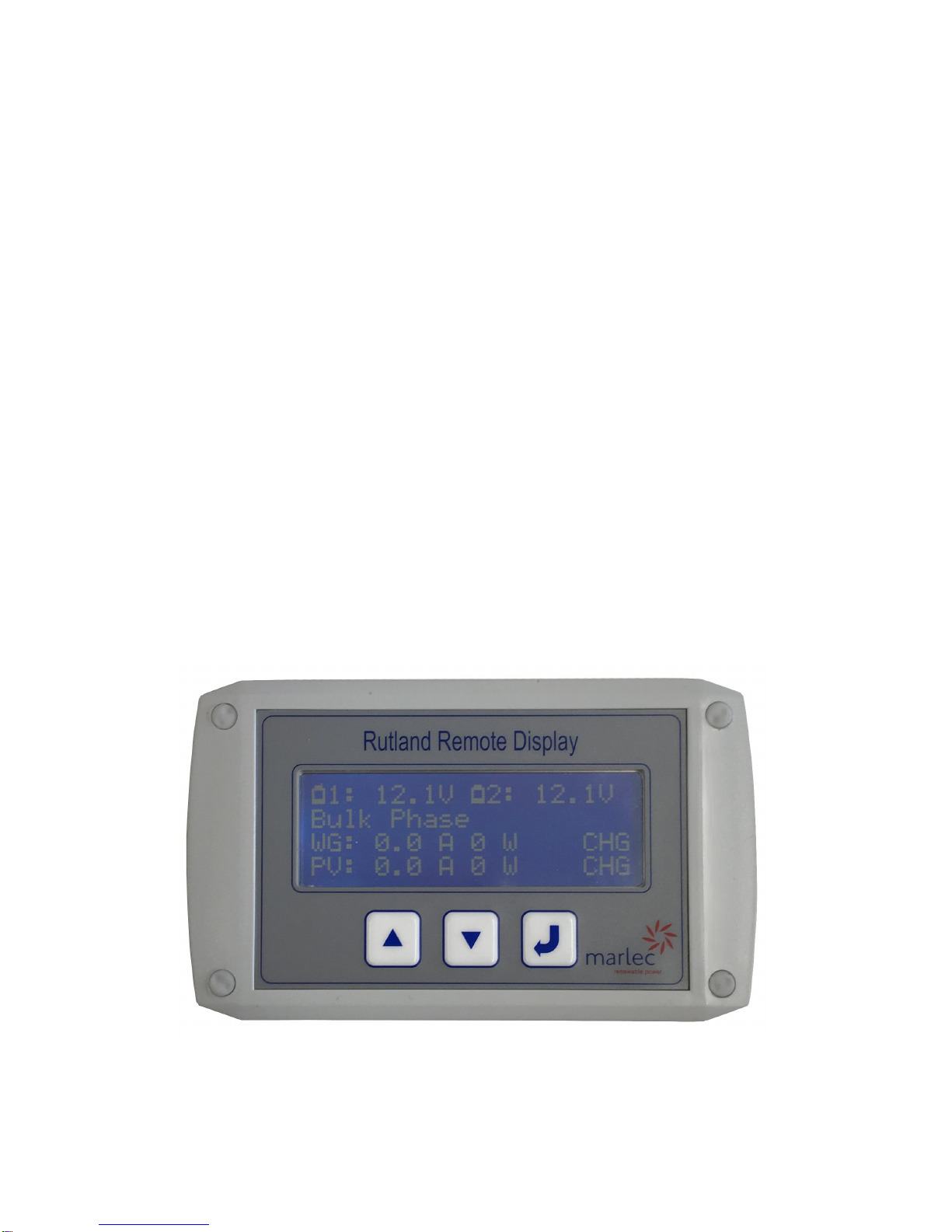
Power Up to Default Screen
Start Monitoring
Press the WG and PV buttons on the 1200 Hybrid Controller.
Amps and Watts for each charge source are displayed. Any one of the following is also displayed:
CHG— Charging,
ON— Charge source is on but there is no voltage to start charging.
SBY– Standby, charge source is on but there is insufficient voltage to start charging.
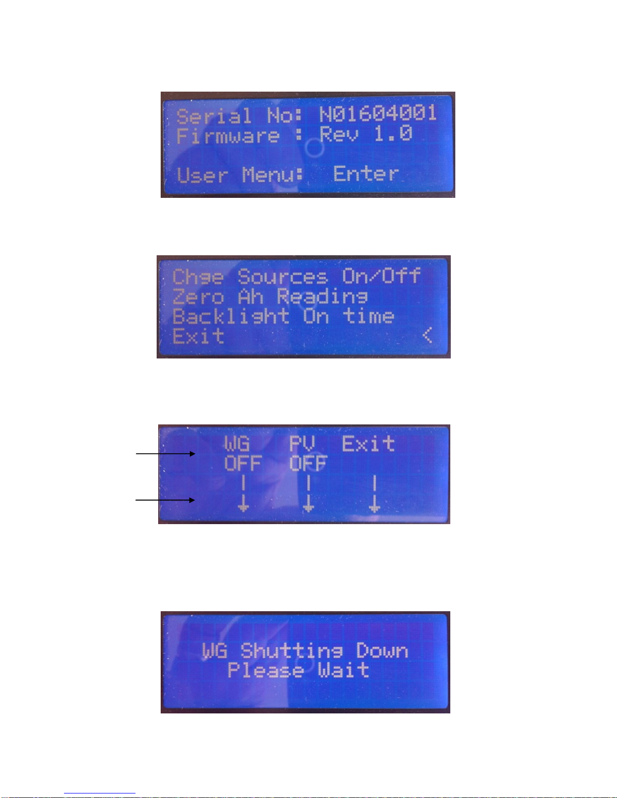
Note: Any button press onthe remotewith the backlight off will switch it on and start it's countdown
timer (default 30s), further button presses when the backlight is on perform functions as shown below.
Using the Remote Display
Press the DOWN and UP buttons to scroll through the available screens;
WG (Amps) - PV (Amps) - Total (Amps) - Default Screen
The screen can be left to display on any screen, the default screen is recommended.
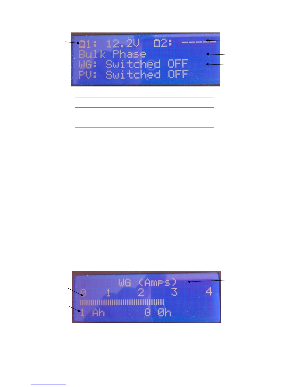
When the charge source, WG or PV, has been shutdown, either at the controller or via the Remote,
SWITCHED OFF is displayed.
Battery 2is shownas
not connected.
Bulk Phase or Float
Phase is displayed
WG = Wind Generator
PV = Photovoltaic
panel
Battery symbols
change to show
approximate level
of charge 0%, 25%,
50%, 75% & 100%
Flashing empty battery Indicates low battery warning
Flashing full battery Indicates regulating mode
WG orPV Switched OFF Coincides with Red illuminated
button on controller
WG or PV or
Total is dis-
played by
scrolling through
UP and DOWN
The scale and bar
graph alter in
response to the
levels of energy to
display
Accumulated
Ampere hours and
duration of
monitoring elapsed
3

Doc No: SM-351 Iss A 18.07.16
MarlecEngCoLtd
Settings
These are accessed via the ENTER key. The first screen displayed shows the controller serial number.
Press ENTER to view the programming menu. Use the UP and DOWN keys to scroll through and ENTER
to select an option. A cursor indicates the option available to select.
Option 1: Charge Sources On/Off
Toggle the UP and DOWN buttons to change between ON and OFF. Press ENTER to Exit.
Note that when switching WG to OFF the controller enters a soft stall routine, this slowly applies the
stall to decelerate the turbine. During this routine, the following is displayed and when complete the
display returns to the programming menu.
ON or OFF is
displayed
Use buttons
below indicated
by the arrows.
4

Doc No: SM-351 Iss A 18.07.16
MarlecEngCoLtd
To Confirm Press ENTER
To Exit and return to the Press UP or DOWN
Option 2: Zero Ah Reading
This function sets to zero all accumulated Ah and elapsed time for both the WG and PV simultaneously.
Option 3: Backlight On Time
This function adjusts the length of time the backlight will remain on following a button press. The
default On time duration is 30 seconds.
Adjust the seconds using the UP and DOWN buttons to the desired duration, one press adjusts one
second. Press ENTER to save this time to non volatile memory and return to the programming menu.
5

Doc No: SM-351 Iss A 18.07.16
MarlecEngCoLtd
Other Display Indications
Controller Over Temperature and Over Current
The following displays coincide with the controller LED display for these conditions. The WG or PV or
both will shutdown and display according to the screen selected as follows:
1. If default screen is selected:
When the condition subsides the normal display is automatically resumed except in the case of PV over
current. See below.
2. If Current screen is selected the WG and PV screens will display as follows:
Caution: PV Over Current
PV Over Current is a permanent error indicating that a PV array current exceeding the maximum
possible 20A has been connected. The error indication is only removed following a controller reset. A
PV array within permissible rating should be connected.
Consult the Rutland 1200 installation manual for further advice.
WG or PV or both
display
Over Temperature
WG or PV or both
display
Over Current
6

Doc No: SM-351 Iss A 18.07.16
MarlecEngCoLtd
L I M I T E D W A R R A N T Y
The Marlec Engineering Company Limited Warranty provides free replacement cover for all
defects in parts andworkmanship for 24 months from the date of purchase. Marlec's obligation in
this respect is limited to replacing parts which have been promptly reported to the seller and are
in the seller’s opinion defective and are so found by Marlec upon inspection. A valid proof of
purchase is required if making a warranty claim.
Defective parts must be returned by prepaid post to the manufacturer Marlec Engineering
Company Limited, Rutland House, Trevithick Road, Corby, Northamptonshire, NN17 5XY, England,
or to an authorised Marlec agent.
This Warranty is void in the event of improper installation, owner neglect, misuse, damage caused
by external factors. This warranty does not extend to ancillary equipment not supplied by the
manufacturer.
No responsibility is assumed for incidental damage. No responsibility is assumed for
consequential damage. No responsibility is assumed for damage caused by user modification to
the product or the use of any unauthorised components.
Manufactured in the UK by
Marlec Engineering Co Ltd
Rutland House
Trevithick Rd
Corby, Norhtants
NN17 5XY
Tel: +44(0)1536 201588
www.marlec.co.uk
Table of contents
Other Marlec Monitor manuals