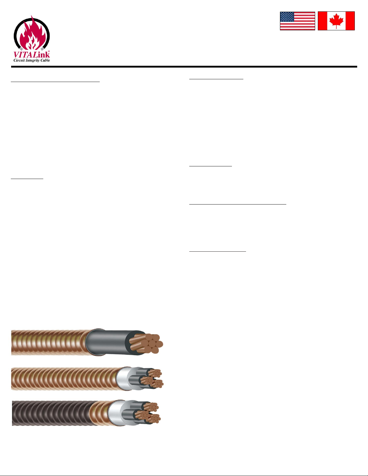
MARMON VITALink MC User manual

VITALink® MC/RC90
Fire-Resistive Cable Certified by UL and ULC IM-120-0
VITALink® MC/RC90 Cables Rev 0
Systems 120/120A/60 7/31/2020
RSCC Wire & Cable LLC © 2020 • 20 Bradley Park Road • East Granby, CT 06026 USA • 800-327-7625 Tel: 860-653-8300 • Fax: 860-653-8321 • r-scc.com 1/7
Installation Instructions
These instructions apply to listed fire-resistive cable. See applicable systems
under “Listings/Certifications/Compliance” on this page. See NFPA 70 Article
728 for a description of Fire-Resistive Cable Systems and their requirements.
Compliance and verification is summarized on the last page. This document
outlines the minimum installation requirements.
The requirements for fire resistive rated systems are more stringent
modifications to the installation rules in the NEC and CE Code. Industry
standard installation practices and workmanship shall be exercised in all
installations. Follow NEC or CE Code rules for cables installed in areas that are
fire protected (Ex. Electrical rooms, etc). Read all instructions before starting.
Description
RSCC’s VITALink® MC/RC90 cable is both UL and cUL listed electrically and fire-
resistive rated for a maximum of 2 hours to UL 2196/ULC S139 for USA and
Canada in sizes 14 AWG through 750 kcmil. The cable is compliant with the
NEC1and Canadian Electrical Code (CE CODE) requirements. The installation
instructions pertain to installing the cable for a 2 hour system therefore, the
cable system described within can be used for RSCC’s 1 hour or 2 hour fire
resistive rated VITALink® MC/RC90 systems.
VITALink® MC/RC90 cable is rated at 600 volts maximum (phase to phase) and
is compliant with the NEC1and Canadian Electrical Code (CE CODE)
requirements for Type MC and and RC90 respectively.
Cable sizes and constructions range from 14 AWG through 750 kcmil and
single conductor to twelve conductor. A complete list of available
constructions is provided within this document and on UL’s website under
FHJR R15365 for USA and FHJR7 R15365 for Canada.
Once a fire resistive rated splice is introduced into the system, please limit the
system use to the hourly fire resistance rating, max voltage and current
allowed for the splice.
Materials Required
Only the components listed in these instructions shall be used to maintain the
respective fire resistive rating. Further details on the materials beyond the list
below are provided inside the document.
1. VITALink® MC/RC90 Cable with or without an overall polymeric jacket, and
with or without ground(s) or segmented groundwire(s).
2. Steel mounting components.
For more information on the certification, please see the system published in
the UL website.
Tools Required
• Utility Knife • Pipe Cutter
• Socket Wrench • Cable Cutter
•Screw Driver
Listings/Certifications/Compliance
The fire resistive cable Certified by UL to UL 2196 and ULC to ULC S139 for use
in the following systems:
2 Hour FHIT/FHIT7 120
2 Hour FHIT/FHIT7 120A
1 Hour FHIT/FHIT7 60
VITALink® MC/RC90 Cable
• Type MC per UL 1569
• Type RC90 per CSA C22.2 No. 123
•See VITALink® MC/RC90 data sheet for other cable listings and certifications

VITALink® MC/RC90
Fire-Resistive Cable Certified by UL and ULC IM-120-0
VITALink® MC/RC90 Cables Rev 0
Systems 120/120A/60 7/31/2020
RSCC Wire & Cable LLC © 2020 • 20 Bradley Park Road • East Granby, CT 06026 USA • 800-327-7625 Tel: 860-653-8300 • Fax: 860-653-8321 • r-scc.com 2/7
General
This document outlines the minimum installation requirements for installing a
cable to the systems described above.
Electrical Circuit Integrity Systems consist of components and materials that are
intended for installation as protection for specific electrical wiring systems, with
respect to the disruption of electrical circuit integrity upon exterior fire
exposure. The specifications for the protective system and its assembly are
important details in the development of the ratings.
These protective systems are evaluated by the fire exposure and water hose
stream test as described in UL 2196 / ULC S139. Ratings apply only to the entire
protective system assembly. Individual components and materials are
designated for use in a specific system(s) for which corresponding ratings have
been developed and are not intended to be interchanged between systems.
Ratings are not assigned to individual system components or materials.
Authorities having jurisdiction should be consulted in all cases as to the specific
requirements covering the installation and use of these Classified systems.
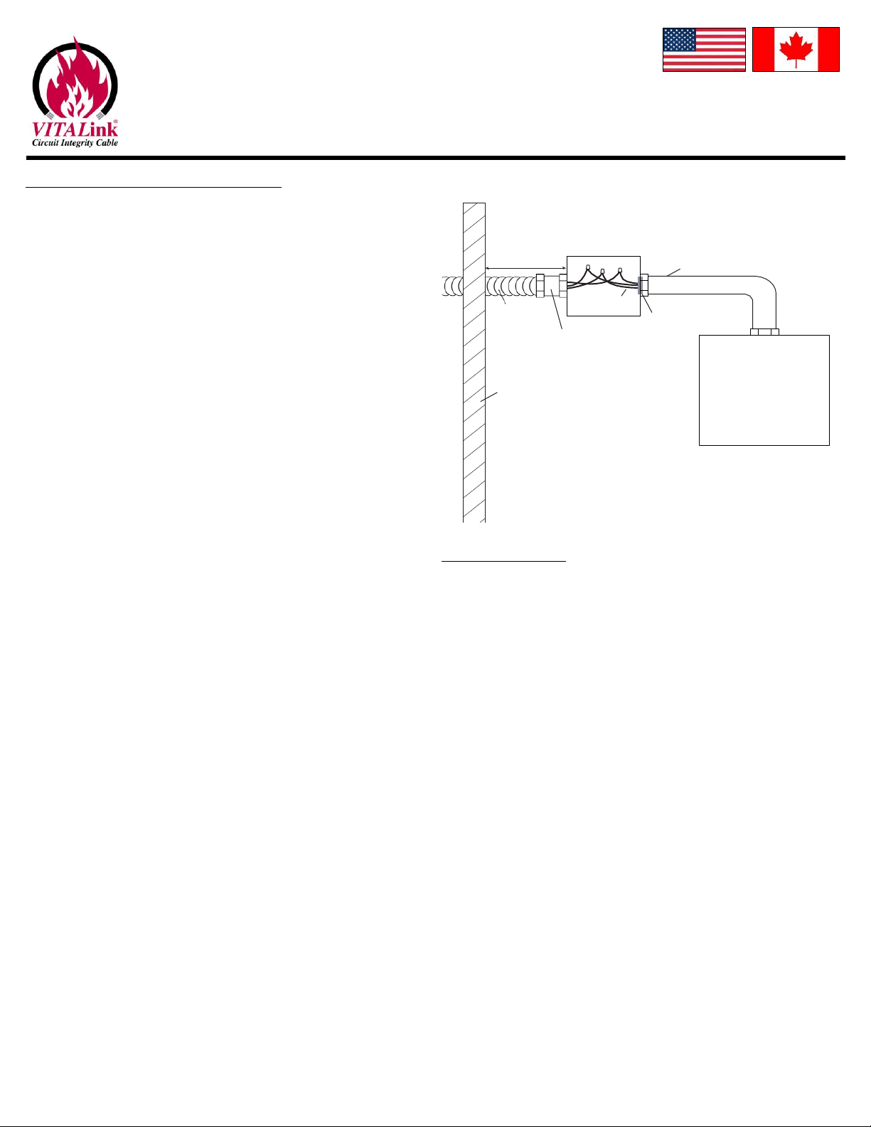
Cables and supports should be routed and supported separately from non-fire
resistive rated circuits. They should be positioned where any hazard of non-fire
resistive rated systems collapsing or failure will not disturb the system.
These requirements must be followed to maintain the hourly rating in the fire
area.
The VITALink® MC/RC90 cable system must be installed by qualified personnel
familiar with generally accepted construction techniques and safe electrical
practices.
Take all appropriate precautions when installing splices, including following
OSHA and other applicable regulations.
The installation must comply with all national and local electrical codes and all
the requirements of the UL Electrical Circuit Integrity System certification
requirements, and carefully follow the installation instructions.
Ensure the cable is in good condition prior to commencing splice installation.
Do not pull cables around corners that have sharp edges, such as corners in
cable trays, or other obstructions. See RSCC VITALink® MC/RC90 General
Installation and Handling Manual for more information.
Cable Support Distance
Cable shall be supported horizontally or vertically every four feet unless
otherwise stated in this document.
Cables shall also be supported on each side of a bend and not to exceed four
feet.
Support Methods
Drywall is not an acceptable means of support.
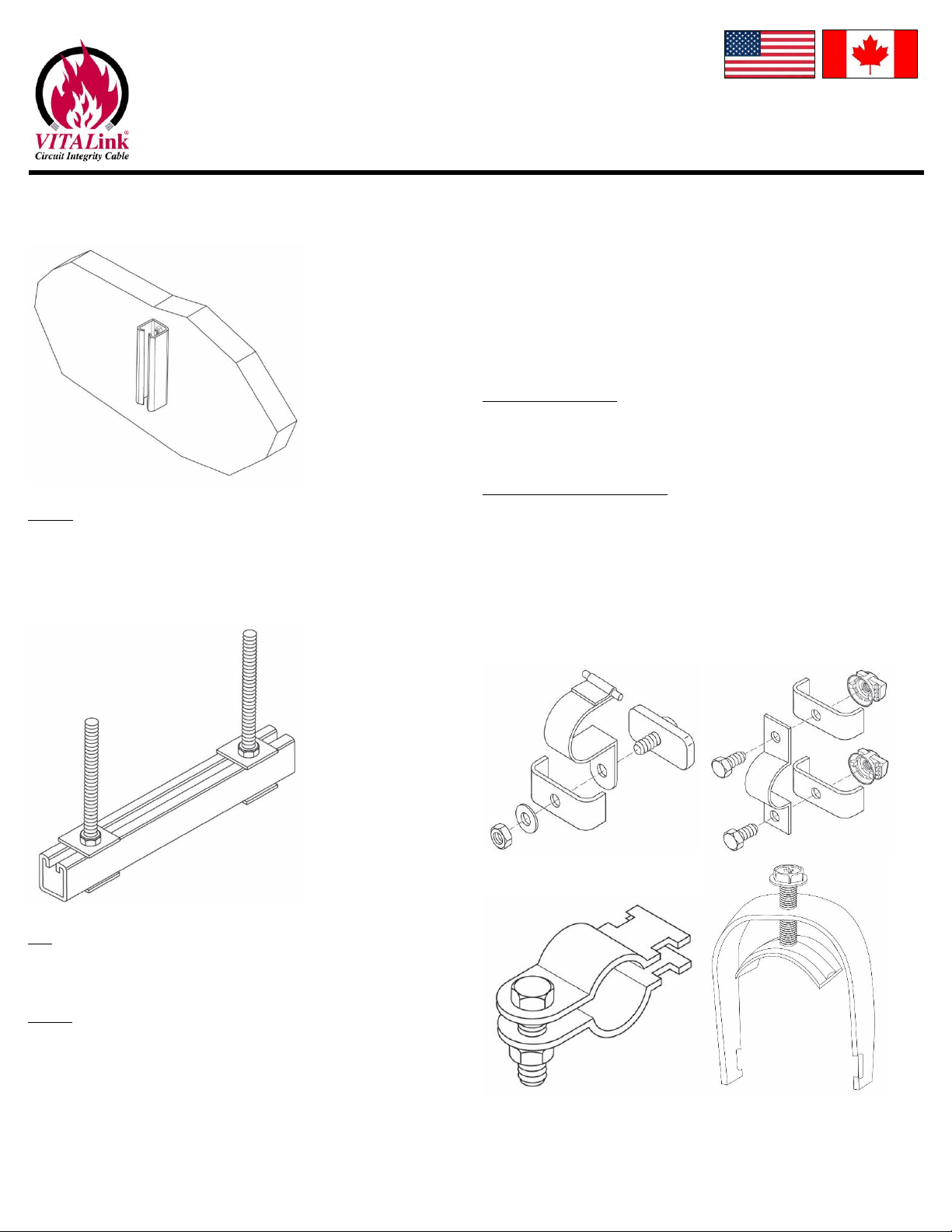
Strut
Box and Cables are mounted on 7/8” or larger 12 gauge slotted steel strut.
Painted or galvanized strut is acceptable.
Strut longer than 20” shall be a minimum of 1-1/2” 12 gauge steel.
Secure strut to concrete wall using a minimum 1/4 inch diameter steel
concrete screws by a minimum 2-1/4 inch in length.
Alternatively, Secure strut to concrete wall using a minimum 1/4 inch
diameter steel masonry anchor by a minimum 1-3/4 inch in length. The
deeper the penetration, the more secure the strut is mounted to the wall.
Please account for spalling.
Strut shall be secured to structure at a minimum on each end, and one in the
center for spans 5 feet or greater. Strut shall, at a minimum, be

VITALink® MC/RC90
Fire-Resistive Cable Certified by UL and ULC IM-120-0
VITALink® MC/RC90 Cables Rev 0
Systems 120/120A/60 7/31/2020
RSCC Wire & Cable LLC © 2020 • 20 Bradley Park Road • East Granby, CT 06026 USA • 800-327-7625 Tel: 860-653-8300 • Fax: 860-653-8321 • r-scc.com 3/7
supported/secured to a 2 hour structure no greater than three feet for
lengths greater than 5 ft.
Trapeze
Trapeze style installation is acceptable using a minimum 3/8” steel threaded
rod with steel strut washers and nuts. Secure strut into 2 hour rated structure
to the appropriate depth to account for supported weight and spalling. 7/8”
strut is not allowed for trapeze style mounting.
Tray
Steel cable tray is an acceptable support method and shall be supported every
five feet.
Conduit
This section applies to cables installed outside of the firezone and in
circumstances acceptable to AHJ.
Some installation may require that the cable is routed through conduit. Cable
should not exceed fill ratio and be de-rated as necessary. Rigid conduit is not
permitted.
EMT or IMC is acceptable for wall penetrations or short sections. Conduits
shall be fire stopped, with a material compatible with plastic and copper,
where the cable enters and exits the conduit. The conduit shall be supported
every five feet. Couplings for steel conduit shall also be steel.
Some conduits are routed underground and enter the building. PVC conduit is
acceptable for these instances as they are directly buried or in concrete.
Where the conduit enters the building, the conduit should be fire stopped.
Routing through PVC conduit is not allowed after entrance into the building.
Cable Securement
Some configurations may require ampacity de-ratings. Follow NEC, CE CODE or
governing code. All straps shall be steel and secure without slack onto cable.
Straps shall be 16 gauge minimum.
Overall Polymeric Jacketed Cable
T&B J-800, two hole one piece strap, two piece single hole with strut nut and
washer on each side of cable (each side of outermost cables if arrayed without
gaps between the straps, Figure 1 below) and in contact with the strap.
Trapeze style horizontal installations shall only use any strap in non-jacketed
section below.
Some illustrations of straps and configurations are provided below.
J-800
1-Piece
2-Piece
Saddle

VITALink® MC/RC90
Fire-Resistive Cable Certified by UL and ULC IM-120-0
VITALink® MC/RC90 Cables Rev 0
Systems 120/120A/60 7/31/2020
RSCC Wire & Cable LLC © 2020 • 20 Bradley Park Road • East Granby, CT 06026 USA • 800-327-7625 Tel: 860-653-8300 • Fax: 860-653-8321 • r-scc.com 4/7
Non-Jacketed Cable (Bare Copper Armor)
T&B J-800, two hole one piece strap, two piece single hole, Cobra Clamp/
Saddle Clamp, two hole Copper or Steel Clips that wrap around cable. Electrical
tape may be used between cable and strap if isolation is required due to
concerns with galvanic action.
Tray
Cables laid in steel tray shall neatly arranged and be secured with steel banding
or steel ties every four feet. Cables shall be installed snug, but not excessively
where cable is damaged. Ties should be compatible with tray, cable and
environment.
Grounding
The Armor may be used as an equipment ground. For grounding equivalents,
see the VITALink® MC/RC90 General Installation and Handling Manual.
Pulling Lubricant
As acceptable by AHJ, Polywater LZ may be used for cables with polymeric
jacket.
Any lubrication non-deleterious or non-corrosive to bare copper is acceptable
for bare copper armored/sheathed cable.
Splicing
2 hour and 1 hour splices are available. Contact RSCC for details.
1-Piece
J-800
Figure 1

VITALink® MC/RC90
Fire-Resistive Cable Certified by UL and ULC IM-120-0
VITALink® MC/RC90 Cables Rev 0
Systems 120/120A/60 7/31/2020
RSCC Wire & Cable LLC © 2020 • 20 Bradley Park Road • East Granby, CT 06026 USA • 800-327-7625 Tel: 860-653-8300 • Fax: 860-653-8321 • r-scc.com 5/7
Terminating at Switchgear/Equipment
When entering an electrical room or other protected area for termination on
equipment/cabinets, a junction box is required on the end of the fire resistive
rated cable in the fire rated room per the following:
1. Once the cable enters the fire rated room, a minimum of 12 inches,
terminate the VITALink® MC/RC90 cable into the appropriate size junction
box per NEC or applicable CE CODE. Use a listed MC/RC90 connector
suitable for a corrugated copper sheath, a listed lock nut and insulating
bushing to terminate the cable to the box. Connector should be suitably
grounded. Equipment grounding conductors should be carried through and
maintained as required. Utilize a grounding hub as required.
2. Using the appropriate raceway for the specified area, connect the junction
box to the equipment.
3. Install appropriate thermoset wiring between the junction box and the
equipment. RSCC’s Firewall® LSZH (NFPA 130 and NFPA 502 complaint) may
be used.
4. Splice VITALink® MC/RC90 to the wire using an approved method. Note a
transition splice may be required based on ampacity considerations.
5. Seal the end of the raceway in the junction box to keep gases from
migrating down into the equipment in the case of a fire. This may be done
using a pliable compound.
Note: All wiring methods and installation procedures shall comply with NEC /CE
CODE and local amendments. NEC Article 110.14 should be considered in
regard to the temperature limit of the wiring to the equipment. The VITALink®
MC/RC90 cable may be sized at 90°C if so desired. CE CODE requirements shall
be observed as applicable.
Other Installations
Contact RSCC Engineering department.
Fire Pump
Controller or
Transfer
Switch
Splice
Junction Box
Min. 12"
Raceway
VITALink
MC/RC90
MC
Connector
Pliable Seal
Fire Rated Wall

VITALink® MC/RC90
Fire-Resistive Cable Certified by UL and ULC IM-120-0
VITALink® MC/RC90 Cables Rev 0
Systems 120/120A/60 7/31/2020
RSCC Wire & Cable LLC © 2020 • 20 Bradley Park Road • East Granby, CT 06026 USA • 800-327-7625 Tel: 860-653-8300 • Fax: 860-653-8321 • r-scc.com 6/7
Parts and Configurations
Cables
All cables listed in FHJR R15365 for the USA and FHJR7 R15365 for Canada sizes
14 AWG through 750 kcmil with or without and overall polymeric jacket, and
with or without ground(s) or segmented groundwire(s). Standard PN’s are per
VITALink® MC/RC90 Cutsheet. Some cables may require custom PN. Common
cables constructions and sizes are provided in Table 1 below.
AHJ Inspection and Compliance
When inspecting the splice and components for compliance to UL 2196/ULC
S139, verify the following:
1. The fire resistive rated cable is VITALink® Type MC and/or Type RC90
printed on the cable.
2. The fire resistive rated system is installed per this document (IM-120-0),
splice instructions if applicable, and the NEC/CE CODE or other governing
code.
UL Inspection
This section is required by UL.
Print to Include
RSCC VITALINK(R) MC/RC90 600V (UL) 2196/(ULC) S139 FHIT/7: 120
FRR 2H 600V | 120A FRR 2H 480V | 60 FRR 1H 480V| [ELECTRICAL
LISTINGS] [PN] [DATE]
Cables are suitable for both control or power use.
1NEC and NFPA are registered trademarks of the National Fire Protection
Agency.
Table 1 - Connector Details and Listed Cable Constructions
Conductor Size
(AWG/kcmil)
RSCC Cable PN
Prefix
Nom Armor
OD (In)
Nom Jacketed
OD (In)
Cable Connector PN
“WSE-WT-“ Series
Connector Hub
Hole Punch
Trade Size
Connector
Body OD
Non-Jacketed
Cable
Jacketed
Cable
1 Conductor
1/0
VM011X0
1.004
1.107
104-100-S3
1”
2”
2/0
VM012X0
1.043
1.146
111-100-S3
1”
2”
3/0
VM013X0
1.075
1.178
111-100-S3
1”
2”
4/0
VM014X0
1.155
1.258
118-100L-S3
1”
2”
250
VM01250
1.215
1.318
125-125-S3
1-1/4”
2.12”
350
VM01350
1.350
1.453
139-125-S3
1-1/4”
2.12”
400
VM01400
1.410
1.513
148-150-S3
1-1/2”
2.5”
500
VM01500
1.500
1.603
157-150-S3
1-1/2”
2.5”
600
VM01600
1.670
1.793
166-150-S3
1-1/2”
2.5”
750
VM01750
1.729
1.852
175-200-S3
2”
3”
2 Conductor
14
VM02014
0.820
0.923
083-075-S3
3/4"
1.5”
12
VM02012
0.820
0.923
083-075-S3
3/4"
1.5”
10
VM02010
0.886
0.989
090-075-S3
3/4"
1.5”
8
VM02008
1.004
1.107
104-100-S3
1”
2”
6
VM02006
1.075
1.178
111-100-S3
1”
2”
3 Conductor
14
VM03014
0.820
0.923
083-075-S3
3/4"
1.5”
12
VM03012
0.886
0.989
090-075-S3
3/4"
1.5”
10
VM03010
0.940
1.043
097-100-S3
1”
2”
8*
VM03008
1.043
1.146
111-100-S3
1”
2”
6*
VM03006
1.155
1.258
118-100L-S3
1”
2”
4*
VM03004
1.235
1.338
125-125-S3
1-1/4”
2.12”
3*
VM03003
1.299
1.402
132-125-S3
1-1/4”
2.12”
2*
VM03002
1.410
1.513
148-150-S3
1-1/2”
2.5”
1*
VM03001
1.585
1.708
166-150-S3
1-1/2”
2.5”
1/0*
VM031X0
1.670
1.793
166-150-S3
1-1/2”
2.5”
2/0*
VM032X0
1.795
1.918
184-200-S3
2”
3”
3/0*
VM033X0
1.915
2.038
193-200-S3
2”
3”
4/0*
VM034X0
2.038
2.161
213-250NJ-S3
213-250-S3
2-1/2”
3.75”
250*
VM03250
2.258
2.412
235-250-S3
2-1/2”
3.75”
350*
VM03350
2.480
2.634
257-250-S3
2-1/2”
3.75”
400*
VM03400
2.710
2.864
285-300-S3
3”
4.5”
500*
VM03500
2.820
2.974
285-300-S3
3”
4.5”
600*
VM03600
3.128
3.302
313-300-S3
3”
4.5”
4 Conductor
14
VM04014
0.886
0.989
090-075-S3
3/4"
1.5”
12
VM04012
0.940
1.043
097-100-S3
1”
2”
10
VM04010
1.004
1.107
104-100-S3
1”
2”
8*
VM04008
1.155
1.258
118-100L-S3
1”
2”

VITALink® MC/RC90
Fire-Resistive Cable Certified by UL and ULC IM-120-0
VITALink® MC/RC90 Cables Rev 0
Systems 120/120A/60 7/31/2020
RSCC Wire & Cable LLC © 2020 • 20 Bradley Park Road • East Granby, CT 06026 USA • 800-327-7625 Tel: 860-653-8300 • Fax: 860-653-8321 • r-scc.com 7/7
Conductor Size
(AWG/kcmil)
RSCC Cable PN
Prefix
Nom Armor
OD (In)
Nom Jacketed
OD (In)
Cable Connector PN
“WSE-WT-“ Series
Connector Hub
Hole Punch
Trade Size
Connector
Body OD
Non-Jacketed
Cable
Jacketed
Cable
6*
VM04006
1.215
1.318
125-125-S3
1-1/4”
2.12”
4*
VM04004
1.350
1.453
139-125-S3
1-1/4”
2.12”
3*
VM04003
1.410
1.513
148-150-S3
1-1/2”
2.5”
2*
VM04002
1.500
1.603
157-150-S3
1-1/2”
2.5”
1*
VM04001
1.729
1.852
175-200-S3
2”
3”
1/0*
VM041X0
1.820
1.943
184-200-S3
2”
3”
2/0*
VM042X0
1.950
2.073
202-200-S3
2”
3”
3/0*
VM043X0
2.123
2.246
213-250NJ-S3
213-250-S3
2-1/2”
3.75”
4/0*
VM044X0
2.258
2.412
235-250-S3
2-1/2”
3.75”
250*
VM04250
2.460
2.634
257-250-S3
2-1/2”
3.75”
350*
VM04350
2.710
2.864
285-300-S3
3”
4.5”
400*
VM04400
3.128
3.302
313-300-S3
3”
4.5”
500*
VM04500
3.128
3.302
313-300-S3
3”
4.5”
5 Conductor
14
VM05014
0.940
1.043
097-100-S3
1”
2”
12
VM05012
1.004
1.107
104-100-S3
1”
2”
10
VM05010
1.075
1.178
111-100-S3
1”
2”
8
VM05008
1.215
1.318
125-125-S3
1-1/4”
2.12”
6
VM05006
1.299
1.402
132-125-S3
1-1/4”
2.12”
4
VM05004
1.480
1.583
157-150-S3
1-1/2”
2.5”
3
VM05003
1.585
1.708
166-150-S3
1-1/2”
2.5”
2
VM05002
1.670
1.793
166-150-S3
1-1/2”
2.5”
1
VM05001
1.915
2.038
193-200-S3
2”
3”
1/0
VM051X0
2.038
2.161
213-250NJ-S3
213-250-S3
2-1/2”
3.75”
2/0
VM052X0
2.258
2.412
235-250-S3
2-1/2”
3.75”
3/0
VM053X0
2.460
2.614
257-250-S3
2-1/2”
3.75”
4/0
VM054X0
2.480
2.634
257-250-S3
2-1/2”
3.75”
6 Conductor
14
VM06014
1.004
1.107
104-100-S3
1”
2”
12
VM06012
1.075
1.178
111-100-S3
1”
2”
10
VM06010
1.155
1.258
118-100L-S3
1”
2”
8
VM06008
1.299
1.402
132-125-S3
1-1/4”
2.12”
6
VM06006
1.410
1.513
148-150-S3
1-1/2”
2.5”
4
VM06004
1.585
1.708
166-150-S3
1-1/2”
2.5”
7 Conductor
14
VM07014
1.004
1.107
104-100-S3
1”
2”
12
VM07012
1.075
1.178
111-100-S3
1”
2”
10
VM07010
1.155
1.258
118-100L-S3
1”
2”
8
VM07008
1.299
1.402
132-125-S3
1-1/4”
2.12”
6
VM07006
1.410
1.513
148-150-S3
1-1/2”
2.5”
8 Conductor
14
VM08014
1.155
1.258
118-100L-S3
1”
2”
12
VM08012
1.215
1.318
125-125-S3
1-1/4”
2.12”
10
VM08010
1.299
1.402
132-125-S3
1-1/4”
2.12”
8
VM08008
1.500
1.623
157-150-S3
1-1/2”
2.5”
9 Conductor
14
VM09014
1.215
1.318
125-125-S3
1-1/4”
2.12”
12
VM09012
1.299
1.402
132-125-S3
1-1/4”
2.12”
10
VM09010
1.410
1.513
148-150-S3
1-1/2”
2.5”
10 Conductor
14
VM10014
1.215
1.318
125-125-S3
1-1/4”
2.12”
12
VM10012
1.299
1.402
132-125-S3
1-1/4”
2.12”
10
VM10010
1.410
1.513
148-150-S3
1-1/2”
2.5”
12 Conductor
14
VM12014
1.235
1.338
125-125-S3
1-1/4”
2.12”
12
VM12012
1.350
1.453
139-125-S3
1-1/4”
2.12”
10
VM12010
1.410
1.513
148-150-S3
1-1/2”
2.5”
*Segmented groundwires available
Note: Non-Fire Rated Connectors will be sized similarly but do not have to be stainless steel.

VITALink® MC
2 Hour Fire Rated Cable
UL FHIT 120/ULC S139 FHIT7 120
Installation Manual

All rights reserved. No part of this manual may be reproduced or utilized in any form or by any means,
electronic or mechanical, including photocopying, recording or by any information storage and retrieval
system, without permission in writing from the RSCC Wire & Cable LLC. Information subject to change
without notice. User to determine suitability for use in their application. RSCC Wire & Cable LLC is not liable
for loss of profits, installation costs or other indirect costs, incidental or consequential damage as a result
of use of this manual. Authorities having jurisdiction should be consulted in all cases as to the particular
requirements covering the installation and use of Listed or Classified products, devices and materials.

VITALink® MC
Installation Manual
Technical Manual 2015
Issue 3
Table of Contents
Section Page
1. Introduction....................................................................................... 1
2. Materials........................................................................................... 5
3. Handling and Storage....................................................................... 5
4. Pulling Calculations .......................................................................... 9
5. Pre-Installation .............................................................................. 18
6. Installation ...................................................................................... 23
7. Post Installation .............................................................................. 28
8. Glossary of Terms .......................................................................... 35
9. References ..................................................................................... 37
10. Appendix 1 ......................................................................................38

RSCC Wire & Cable LLC © 2015 • 20 Bradley Park Road • East Granby, CT 06026 • 800-327-7625 • 800-653-8300 • Fax: 860-653-8321 • www.vitalinkcable.com
1
1. Introduction
This manual covers installation, and termination
recommendations for VITALink®MC cable. It is
assumed that the cable has been properly sized
and the installation properly designed. Since this
manual is only a guide and all situations cannot
be covered, please call the RSCC Engineering
Department for special installations.
There are nine sections to this manual, starting
with this introduction. The second section pro-
vides material recommendations, with detailed
information in Appendix 1. Handling and stor-
age information is presented in section three.
An overview of calculations that should be per-
formed prior to installation, including pulling
tension, bend radius and cable fill are then
presented. Pre-installation information, including
minimum installation temperature, precautions,
installation equipment, setup, pull tension
monitoring, and cable attachment methods
are next. Installation recommendations for
UL System 120/ULC S139 FHIT7 120, as well
as general recommendations follow. Post
installation activities are then discussed. The
last two sections contain a glossary of terms
and references.
VITALink®MC
NEC Fire Rated Applications:
The NEC recognizes critical electrical circuits
which, in the event of a fire, must continue to
perform their intended functions. NEC Article
695 and Article 700 address “Fire Pump” and
“Emergency System” applications respective-
ly. Both require a minimum of a 2-hour fire
resistance rating which can be achieved
through various methods. This requirement is
applicable to the following:
• Fire Pump Feeders
• Emergency Generator Feeders
• Emergency Exhaust Fans
• Emergency Lighting
• Exit Signs
• Firemen’s Elevators
Fire Resistive Cable Issues:
One of the options available to designers was
to specify a cable system which was qualified to
meet the fire endurance requirements of the
code. Mineral Insulated (Type MI) cables
emerged as the only available technology to
meet this stringent requirement.
Although these cables did fulfill the code require-
ments, they suffered from many inherent prob-
lems which manifested in end user difficulties.
Installation problems such as cable stiffness,
special mounting procedures, susceptibility to
moisture, custom connectors, and termination
difficulties forced installers to expend time, labor
and resources to overcome these hurdles.
Designers had to deal with product limitations
that included severe length restrictions and very
narrow product offering with respect to size and
cable configuration.
These issues have led to a reluctance by both
installers and designers to utilize fire resistive
cables. They have pursued costly alternatives
such as rerouting, fire proof coating & wrapping
systems, and embedding cable in concrete.
The VITALink®MC Solution:
VITALink®MC is a “user friendly” fire resistive
cable which incorporates the ease and familiarity
of Type MC with a 2 hour fire endurance rating.
This is accomplished through the use of our
revolutionary Fire-Roc™ insulation material.
This proprietary thermoset inorganic insulation
is applied through the use of a conventional
extrusion process, allowing for long lengths and
a wide product array typical of standard Type
MC cables.
VITALink®MC allows designers to specify with-
out the burden of product limitations; while
enabling installers to reap the benefits of Type
MC convenience.

RSCC Wire & Cable LLC © 2015 • 20 Bradley Park Road • East Granby, CT 06026 • 800-327-7625 • 800-653-8300 • Fax: 860-653-8321 • www.vitalinkcable.
com
2
Termination Simplicity
Tools required
to terminate
VITALink®MC.
Tools required
to terminate
Type MI.

RSCC Wire & Cable LLC © 2015 • 20 Bradley Park Road • East Granby, CT 06026 • 800-327-7625 • 800-653-8300 • Fax: 860-653-8321 • www.vitalinkcable.com
3
Features
• 2-hour fire rating
• Available as a VFD cable with segmented grounds
• Low smoke, halogen free design
• Simple to terminate with commercially available brass or stainless steel
MC connectors
• Printed number coding allows for easy circuit identification
• Uses conventional tools for terminating
• Available in long lengths
• Welded armor forms an impervious barrier
• Armor is impact & crush resistant
• Fire-rated splice available (FHIT 120)
Applications
Emergency circuits:
• Ventilation
• Lighting
• Communications
Performance Standards
• UL listed, NEC Type MC in accordance with UL Standard 1569
• UL listed as 2-hour fire rated in accordance with ANSI/UL 2196, maximum 480 volts under fire conditions
• Electrical Circuit Integrity Systems (FHIT) — System No. 120 of the UL Fire Resistance Directory
• Meets and exceeds fire rated cable requirements in NFPA 130 for Transit applications and NFPA 502 for
Highway Tunnel applications
• Rated FT-4 / IEEE 1202 Vertical Flame test; ST1, limited smoke
• For use in wet locations to 90°C
• Armored with copper sheath that exceeds the NEC requirement for equipment grounding conductor
• Complies with NFPA 130 and NFPA 502 for total smoke released and low toxicity
Construction
Conductor: Annealed copper, Class “B” strand per ASTM B-170 & B-8
Insulation: Thermoset, low smoke zero halogen silicone rubber
Circuit Identification: Printed numbers per ICEA Method 4
Inner Jacket: Thermoset, low smoke zero halogen silicone rubber
Armor: Continuously welded and corrugated copper
Outer Jacket: Black low smoke, zero halogen polyolefin (colors available on request)
* Rated 90°C for normal operation, 130°C for emergency
overload conditions, and 250°C for short circuit conditions.
Scope
VITALink®MC Transit is a 600 volt power
cable with a 2-hour fire-rating when
installed in accordance with the VITALink
Installation Manual and Installation Guide.
This cable meets the requirements of
UL 2196 Fire Resistive Cable Standard
as a 2-hour “Electrical Circuit Integrity
System”. It was specifically designed
to meet both the electrical and fire-
resistive cable requirements of NFPA
130 and NFPA 502 for Emergency
Communications, Emergency Lighting &
Emergency Ventilation.
90°C*, 600 Volt
NEC Type MC
UL Listed
UL Electrical Circuit
Integrity System (FHIT 120)
VITALink®MC Transit
2-Hour Fire Rated Power Cable
www.vitalinkcable.com
Insulation
Proprietary Fire-Roc™ layer
Inner Jacket
Proprietary Fire-Roc™ layer
Armor
Continuously welded and corrugated copper
Jacket
Low Smoke Zero Halogen (LSZH)
Conductor
Annealed copper
Class “B” strand

RSCC Wire & Cable LLC © 2015 • 20 Bradley Park Road • East Granby, CT 06026 • 800-327-7625 • 800-653-8300 • Fax: 860-653-8321 • www.vitalinkcable.
com
4
VITALink®MC Transit 2 Hour Fire Rated Power Cable
Consult factory for availability and minimum quantity requirements
Product Code
Size
(AWG kcmil)
Number of
Conductors
Nominal Core
Diameter
(In)
Nominal Armor
Diameter
(In)
Nominal Cable
Diameter over Outer Jacket
(In)
Approximate
Net Weight
(Lbs/1000 ft)
VM02014-X00 14 2 0.49 0.82 0.92 490
VM03014-X00 14 3 0.52 0.82 0.92 510
VM04014-X00 14 4 0.57 0.89 0.99 580
VM02012-X00 12 2 0.53 0.82 0.92 522
VM03012-X00 12 3 0.56 0.89 0.99 599
VM04012-X00 12 4 0.62 0.94 1.04 670
VM02010-X00 10 2 0.58 0.89 0.99 604
VM03010-X00 10 3 0.61 0.94 1.04 685
VM04010-X00 10 4 0.67 1.00 1.10 767
VM03008-X00 8 3 0.72 1.04 1.14 838
VM04008-X00 8 4 0.80 1.16 1.26 977
VM03006-X00 6 3 0.80 1.16 1.26 1,020
VM04006-X00 6 4 0.89 1.22 1.32 1,158
VM03004-X00 4 3 0.91 1.24 1.34 1,246
VM04004-X00 4 4 1.01 1.35 1.45 1,510
VM03003-X00 3 3 0.97 1.30 1.40 1,410
VM04003-X00 3 4 1.07 1.41 1.51 1,700
VM03002-X00 2 3 1.04 1.41 1.51 1,649
VM04002-X00 2 4 1.15 1.50 1.60 1,940
VM03001-X00 1 3 1.20 1.59 1.71 1,990
VM04001-X00 1 4 1.33 1.73 1.85 2,550
VM011X0-X00 1/0 1 0.65 1.00 1.10 920
VM031X0-X00 1/0 3 1.29 1.67 1.79 2,350
VM041X0-X00 1/0 4 1.43 1.82 1.94 2,750
VM012X0-X00 2/0 1 0.70 1.04 1.14 1,030
VM032X0-X00 2/0 3 1.38 1.80 1.92 2,757
VM042X0-X00 2/0 4 1.54 1.95 2.07 3,320
VM013X0-X00 3/0 1 0.75 1.08 1.18 1,189
VM033X0-X00 3/0 3 1.50 1.92 2.04 3,321
VM043X0-X00 3/0 4 1.68 2.12 2.25 3,950
VM014X0-X00 4/0 1 0.80 1.16 1.26 1,360
VM034X0-X00 4/0 3 1.62 2.04 2.16 4,007
VM044X0-X00 4/0 4 1.82 2.26 2.38 4,680
VM01250-X00 250 1 0.89 1.22 1.32 1,620
VM03250-X00 250 3 1.81 2.26 2.38 4,380
VM04250-X00 250 4 2.01 2.46 2.61 5,470
VM01350-X00 350 1 0.99 1.35 1.45 2,000
VM03350-X00 350 3 2.03 2.48 2.63 6,242
VM04350-X00 350 4 2.26 2.71 2.86 7,050
VM01500-X00 500 1 1.12 1.48 1.58 2,575
VM03500-X00 500 3 2.31 2.82 2.97 7,721
VM04500-X00 500 4 2.58 3.13 3.30 9,520
VM01750-X00 750 1 1.33 1.73 1.85 3,455
Note: For other sizes and configurations not shown above please consult RSCC Customer Service Representative.

RSCC Wire & Cable LLC © 2015 • 20 Bradley Park Road • East Granby, CT 06026 • 800-327-7625 • 800-653-8300 • Fax: 860-653-8321 • www.vitalinkcable.com
5
3. Handling and Storage
2. Materials
5
VITALink MC cables are very durable, but the
following general handling and storage guide-
lines should be observed. These sections pro-
vide prudent storage and handling measures
that shall be followed to minimize the possibility
of cable damage.
Storage
Cables shall be stored to protect them
against physical damage and the environment.
Protection from construction equipment, falling
objects, chemical spills, and other hazards
should be considered in selecting storage areas
and environments. Fencing or other barriers
may be used to protect cables and reels
against damage by vehicles or other equipment
moving about in the storage area. Reels shall
be stored upright on their flanges, not stacked
(see Figure 1). See Figure 2 for definitions of
reel components. Handling shall be in a manner
that prevents deterioration of and physical dam-
age to the reel and to the cable (see Figure 1).
To prevent cables from settling into soft ground
and prevent reels from rotting, storage should
be on a firm surface, paved if possible, or on
planking in an area with good drainage. For
these reasons, storage of cable should, prefer-
ably, be indoors.
Cables are protected from the direct effects of
weather with wrapping or lagging when
shipped. When received, the protective cover-
ing or wrap on the cable should be inspected for
evidence of shipment damage. Whenever pos-
sible, the factory applied protective cover
should be left in place until removal is absolutely
necessary. Additional covering should be used
to protect against the effects of the environment
in which the cable is stored, such as outdoors
or in excessively dirty, dusty areas. The cover
should be resistant to the environment and
should be chosen to shield cables from the
deleterious effects of the sun. If possible, venti-
lation should be provided to dissipate any
heat buildup.
Both ends of the cable on a reel should be
securely fastened to the reel flange, and sealed
to prevent entrance of moisture. When shipped,
the exposed ends of RSCC cables are protect-
ed by shrinkable, molded polyolefin end caps.
These caps are weatherproof and should ade-
quately seal the cable against moisture and
other contaminants during shipment and stor-
age. Whenever end seals are damaged, miss-
ing, or removed look for moisture in the cable. If
moisture is found, use suitable measures to dry
the cable core and rectify any deleterious effects
of the moisture, such as corrosion, prior to
installation. If storage is outdoors or in an envi-
ronment where considerable dirt and moisture
are present, protection of the exposed cable
ends with shrinkable, molded polyolefin end
caps or other suitable means is recommended.
Handling
Cables should only be handled or installed with-
in suitable temperature limits (see Section 5,
Minimum Installation Temperature). Cable reels
Recommendations for fittings and other materi-
als for use with VITALink MC are shown in
Appendix 1. Other commercially available mate-
rials may work as well. It is suggested that the
manufacturer be contacted for recommen-
dations and instructions on the use of their
products.
The design should allow additions, replacements,
and other changes to be made easily, at minimum
cost, and with minimum interruption of service.

RSCC Wire & Cable LLC © 2015 • 20 Bradley Park Road • East Granby, CT 06026 • 800-327-7625 • 800-653-8300 • Fax: 860-653-8321 • www.vitalinkcable.
com
6
How To Handle Cable Reels
YES
Always load and store reels
upright on their flanges and
block securely.
Reels can be hoisted with a
properly secured shaft extend-
ing through both flanges.
Cradle both reel flanges
between fork tines.
Lower reels from a truck using a
hydraulic gate, hoist or fork lift.
LOWER CAREFULLY.
NO
Upended heavy reels will often
be damaged.
Do not lift by a single reel flange.
Cable or reel may be damaged.
Never allow fork tines to touch
the cable surface or reel wrap.
Never drop reels.
Figure 1. Reel Handling

RSCC Wire & Cable LLC © 2015 • 20 Bradley Park Road • East Granby, CT 06026 • 800-327-7625 • 800-653-8300 • Fax: 860-653-8321 • www.vitalinkcable.com
7
Figure 3. Reel Rolling
Roll reel in the direction
indicated by the arrow.
T
DF
d
Arbor
Hole
Figure 2. Reel Components
F = Flange Diameter
T = Inside Traverse Width
D = Drum Diameter
d = Depth
should be handled utilizing equipment designed
for that purpose. Reels of cable must not be
dropped from any height, particularly from trucks
or other transporting equipment. Lifting or han-
dling of cable reels should be done in such a
manner that the lifting/handling device does not
make direct contact with the cable or its protec-
tive covering. Care shall also be taken so that
the flange of one reel does not impact cable on
another reel. If any of these cases occur, the
cable shall be examined for damage. The fol-
lowing methods are recommended for lifting of
cable (see Figure 1):
• A crane or boom type equipment may be used
by inserting a suitable shaft, which is properly
secured, through the reel arbor hole and lifting
with slings. A spreader or other device should
be used to minimize sling pressure against the
reel flange.
• Forklift type equipment may be used to move
smaller, narrower reels. Fork tines should be
placed so that lift pressure is on the reel
flanges, not on the cable, and must reach all
the way across the reel so the lift is against
both reel flanges.
• Reels may be moved short distances by
rolling. Reels should be rolled in the direction
that the cable is wound (see Figure 3). This
will tend to tighten the cable windings, not
loosen them. Surfaces over which the reels
are to be rolled should be firm, level, and clear
of debris including protruding stones, stumps,
and other material which may damage the
cable if the reel straddles them. Make sure
there are no objects in the way that could
damage the cable surface by preventing the
reel flanges from bearing the total weight.
Table 1 provides capacities of standard RSCC
shipping reels. If a cable is transferred to another
reel, the drum diameter of the reel shall be equal
to, or greater than the original reel drum diame-
ter, as shown in Table 2. Reel flanges should be
in good condition to prevent damage to the
cable. The reel should be capable of accommo-
dating the cable length with at least 1 1/2 inches
of clearance below the top of the flange. The reel
shall have an adequate weight capacity. Care
shall be taken to assure that cable limits for
bending radius are not violated and the cable is
not twisted during rereeling or installation.
Appropriate precautions for reeling and unreel-
ing should be followed (see Section 5).
Identification and/or marking information shall be
transferred to the new reel using a permanent
marking method.
Cables shall be handled carefully during
unreeling to prevent damage due to kinking or
bending to radii smaller than allowable limits.
During handling, cables shall not be laid on
rough ground, run over, dragged over sharp
objects or other such treatment that could cause
damage.
R
S
C
C

RSCC Wire & Cable LLC © 2015 • 20 Bradley Park Road • East Granby, CT 06026 • 800-327-7625 • 800-653-8300 • Fax: 860-653-8321 • www.vitalinkcable.
com
8
* NOTE: Shaded area indicates that the chosen reel size is too small for corresponding cable.
Table 1. VITALink MC*Length Capacities On Standard Shipping Reels
Cable Type Cable Diameter Range
(Inches)
Minimum Drum Diameter As A
Multiplier Of Cable Diameter
VITALink MC All Sizes 20 X
Table 2. Minimum Reel Drum Diameter
Flange (Inches) 48 48 66 72 84 87
Traverse (Inches) 18 32 32 40 48 60
Drum (Inches) 24 24 30 40 48 60
Tare Wt: (Lbs) 110 194 350 520 750 880
Max. Net: (Lbs) 6,000 6,000 6,000 9,000 15,000 14,000
Maximum Diameter Reel Capacity In Feet
0.700 3,300 6,058 12,520 16,021 26,243 27,146
0.800 2,488 4,579 9,495 12,584 19,926 20,923
0.900 1,860 3,433 7,572 9,918 15,907 16,091
1.000 1,513 2,800 6,038 7,790 12,698 13,345
1.100 1,230 2,283 5,130 6,559 10,799 10,093
1.200 997 1,855 4,062 5,536 8,561 9,236
1.300 - - 3,450 4,672 7,279 7,660
1.400 - - 2,927 3,934 6,183 6,312
1.500 - - 2,723 3,296 5,758 5,881
1.600 - - - 3,082 4,897 4,816
1.700 - - - 2,572 4,139 4,525
1.800 - - - 2,422 3,901 3,657
1.900 - - - 2,003 3,278 3,458
2.000 - - - 1,898 3,107 3,280
2.100 - - - - 2,584 2,599
2.200 - - - - 2,461 2,476
2.300 - - - - 2,349 2,364
2.400 - - - - 1,925 2,262
2.500 - - - - - 1,734
2.600 - - - - - 1,665
2.700 - - - - - 1,600
2.800 - - - - - 1,540
2.900 - - - - - 1,485
3.000 - - - - - 1,433
3.100 - - - - - -
3.200 - - - - - -
3.300 - - - - - -
3.400 - - - - - -
3.500 - - - - - -

RSCC Wire & Cable LLC © 2015 • 20 Bradley Park Road • East Granby, CT 06026 • 800-327-7625 • 800-653-8300 • Fax: 860-653-8321 • www.vitalinkcable.com
9
When cables are pulled into raceways or trays,
they are likely to be subjected to physical
stresses that they will never again be required
to endure. The prime cause of pulling forces is
the friction of the cable against the supporting
and contact surfaces. If the supporting surface
is straight and horizontal, this friction is caused
by the weight of the cable in contact with this
surface. If the surface is not horizontal, the
weight of the cable also affects the pulling load,
but is dependent upon the angle of inclination.
This angle may add to or lessen the total pulling
force, depending upon whether the pull is up or
down.
When a cable is pulled around a bend, it is in
contact against the inner arc of curvature of the
bend. If any substantial amount of pulling force
has been developed in the cable, the friction
load due to the pressure at this point will greatly
surpass that due solely to the weight of the
cable. Thus, bends in the run increase the
pulling load significantly.
Factors that shall be considered prior to
installation, to minimize the possibility of cable
damage, are as follows:
• Tensile strength of the conductors
• Method of attachment to the cable
• Sidewall pressure
• Estimated pulling tension
• Force required to pull the cable off the reel
• Coefficient of friction between the cable and
adjacent surfaces
• Percentage of raceway area filled
• Bend radius
Each of these items is discussed in the follow-
ing sections starting with tension calculations.
Two tension calculations are required for each
cable installation. The first calculation is the
“Maximum Allowable Pulling Tension” for the
particular cable to be installed. This value is
dependent upon the method of attachment to
the cable, the allowable sidewall bearing pres-
sure, and the construction of the cable.
Secondly, knowing the weight of the cable and
the details of the installation configuration, the
“Estimated Pulling Tension” that may occur
during installation can be calculated.
Maximum Allowable Pulling
Tension
The maximum allowable pulling tension on the
cable(s) is the lesser of the maximum allowable
tension based on conductor strength (Tc), the
maximum allowable tension based on sidewall
pressure (Tp), and the limit based on the
attachment method to the cable.
Conductor Tensile Strength
It is assumed that the method used to attach
the cable to the pull rope transfers all forces to
the conductor. The tensile strength of the con-
ductor then becomes a limiting factor for the
force that can be applied. Copper elongates
slightly before breaking, which changes the
resistance characteristics. A safety factor is
used to prevent this, as well as other items.
This tension is determined by the following for-
mula:
Tc= K x F x kcmilT
Tc = Maximum allowable tension based
on conductor tensile strength (pounds)
K = Factor based on material strength
with a safety margin;
8 for annealed copper
F = Factor to account for possible
unequal tension distribution
kcmilT= The sum of the circular mil area of
all conductors in thousand circular
mils (kcmil)
4. Pulling Calculations

RSCC Wire & Cable LLC © 2015 • 20 Bradley Park Road • East Granby, CT 06026 • 800-327-7625 • 800-653-8300 • Fax: 860-653-8321 • www.vitalinkcable.
com
10
When all conductors are the same size, the
equation becomes:
Tc= K x F x kcmil x N
kcmil = Circular mil area of one conductor
in thousand circular mils (kcmil)
N = Total number of conductors pulled
The tension distribution factor (F) is 1 for a sin-
gle multiconductor cable, 0.8 when pulling
more than one cable of equal conductor size,
and 0.6 when pulling multiple cables of unequal
conductor size. Ground wires and armor should
not be considered in these computations. The
conductor circular mil area, and the conductor
strength for one and three annealed copper
conductor(s) of a single cable (N=1 and 3, and
F=1) using the above equation is provided in
Table 3.
Cable Attachment Limit
The maximum allowable tension is also limited
by the ability of the device used to connect the
cable to the pull rope to withstand the forces
applied. When pulling by gripping the conduc-
tors with a pulling eye or bolt, the maximum ten-
sion is usually limited to 10,000 pounds. This is
dependent upon the pulling eye or bolt used
and the method of application. The manufac-
turer’s recommendations should be followed.
When the insulated conductors are gripped with
a properly sized and applied basket weave grip,
the limit is 200 pounds per grip. This is based
upon the hoop stress applied with a basket grip
and the cable construction. Since the attachment
by a grip is limited by the slip of the insulation,
the insulation may be removed, and friction tape
applied over the conductor to increase the pull
by grip limit. For this configuration, with a properly
sized and applied grip, the limit is 2000 pounds.
Sidewall Pressure
When a cable is pulled around a bend, radial
force is exerted on the insulation, armor, and
jacket as the cable is pressed against the inner
arc of the bend (see Figure 4). This is referred
to as sidewall pressure and is expressed as
pounds per foot of radius.
Sidewall pressure is important in cable pulling
calculations for two reasons. The first is its
increase in the total pulling tension due to
greater pressure between the cable and the
bend. The second is its crushing effect upon the
cable insulation and the possibility of permanent
damage to the insulation and/or the cable armor
if excessive sidewall pressures are permitted.
Sidewall pressure is usually the determining
factor when establishing maximum allowable
pulling tension for large conductor sizes.
The maximum value for sidewall pressure
depends on the cable design. For VITALink MC
it is normally 400 pounds per foot of bend, with
a 10 times pulling radius multiplier. Under cer-
tain circumstances it may be necessary to
reduce the bend radius multiplier to 7 times
(which is provided for permanent training). For
this case, the sidewall pressure should not
exceed 300 pounds per foot of bend. The for-
mula for sidewall pressure for a single cable is
as follows:
Tp= SWP x R
Tp= Maximum allowable tension which
will not exceed the sidewall pressure
limit in pounds*
SWP = Sidewall pressure limit in
pounds per foot
R = Radius of bend in feet
* This value may be more limiting than the
maximum tension Tc based on conductor
strength. The lower value of the two governs.
Radius Of Bend
Sidewall Pressure
Tension
Figure 4. Sidewall Pressure
This manual suits for next models
1
Table of contents
Popular Cables And Connectors manuals by other brands

Flash butrym
Flash butrym DMX SPLITTER 8 User's manual & operating instructions

Converters.TV
Converters.TV 757 Operation manual

Keysight
Keysight N4697J Operating and service manual

SolidView
SolidView PS-2002 user manual

Big Sprinkler
Big Sprinkler 4200HR Instruction Manual for Operation & Maintenance

Festo
Festo NEBCM12G8-E LE8 Series Instructions & assembly