Maselec MPL-2 User manual

MPL-2
Peak & High Frequency Limiter
http://www.maselec.com

MASELEC MPL-2
Peak & High Frequency Limiter
Page 2 of 5
INTRODUCTION
The MASELEC model MPL-2 limiter was designed to:
Prevent peak levels from exceeding a pre-set limit.
Increase subjective loudness of programmes.
Give digitally recorded programmes a more ‘analogue’ character.
Introduce a soft 'levelling' function for large differences in average programme levels.
Reduce dynamic range of programmes to maximize the performance of AD converters.
Add no audible 'pumping' resulting from limiting.
Have a well-defined threshold, with no need for programme related adjustments.
DESCRIPTION
The MPL-2 is housed in a 1U 19" rack mount alloy case.
A minimum of controls is used due to automatic time constants and optimisation techniques for the
gain reduction. The advantage is not only simple operation but also increased performance for highly
dynamic and inconsistent materials without the need for continuous readjustments.
The input gain does not reduce the wide dynamic range of the limiter. It can be used at its maximum
setting with no increased risk of distortion. This eliminates the need for excessive levels, which could
cause clipping in equipment feeding the input of the limiter. A further benefit is that the maximum
peak output level (set with the threshold) is independent of different gain settings.
High Frequency Limiting is primarily intended for use as a de-esser, reducing unattractive high
frequencies. Part of the high frequency limiter circuit is also used to reduce distortion from the wide-
band limiter.
Users of the MPL-2 will notice the removal of spurious peaks, and an increase of subjective levels,
without the coloration and increased distortion so often associated with soft clippers and other ultra
fast limiters.
1. Input Gain
2. Limiter ‘on/off’
3. Limiter ‘hard’
4. Limiter Threshold
5. HF Limiter Threshold
6. HF Limiter ‘on/off’
7. HF Limiter side-chain M-S
8. Bypass

MASELEC MPL-2
Peak & High Frequency Limiter
Page 3 of 5
LIMITER
The diagrams above show how the limiter reduces the output level by 3 dB without overshoot
or distortion of the waveform.
HF LIMITER
input: 1 kHz burst +22 dBu output: threshold = +18 dBu
Output frequency response when
the HF limiter is adjusted for max.
high frequency reduction.
4dB reduction: 5msec attack.
10 dB reduction: 1 msec attack
This shows how the attack time
becomes shorter when high
frequency reduction is increased.

MASELEC MPL-2
Peak & High Frequency Limiter
Page 4 of 5
OPERATION
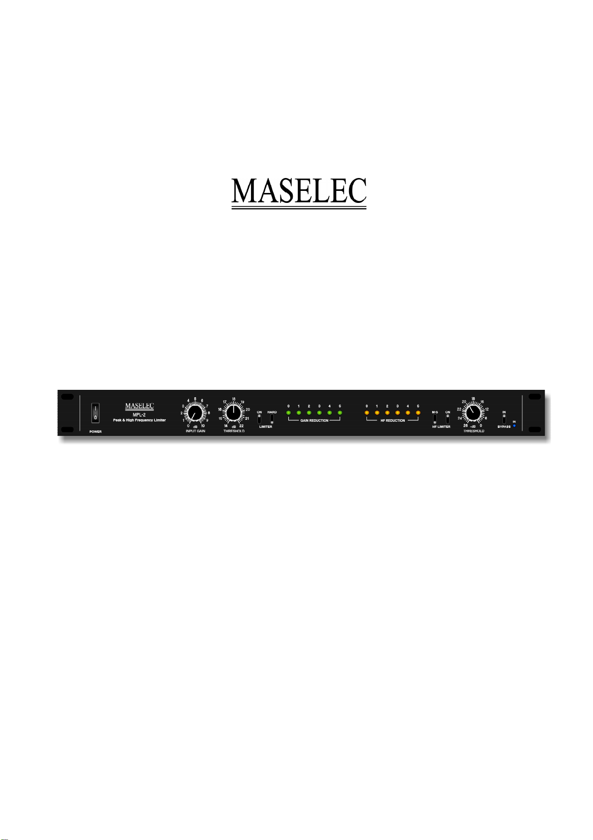
INPUT GAIN…….. 0dB to 10dB. Adjust the gain to achieve desired amount of limiting.
THRESHOLD….... +14dBu to +22dBu. The limiter threshold is normally adjusted to just below
(limiter) maximum peak operating level. Further adjustments should not be necessary.
Note: This control relates to peak programme level. Do not use sine waves
(steady tones) to adjust, instead use programmes. You could increase the input
gain to make it easier find the threshold that stops ‘overs’ and then re-adjust the
gain after the threshold has been set.
HARD………..…... This control changes the limiter character to:
• Harder knee
• Shorter release time
• Slightly more aggressive increase of loudness
The ‘HARD’ mode is particularly useful for percussive programmes and should be
used with care for softer, low- to mid-frequency programmes.
HF THRESHOLD.. Adjust this control to set the amount of high frequency limiting. The limiter setting
affects this control: The HF threshold is relative to the limiter threshold as if the
two controls are in series (also when the limiter is off).
M-S………………..Switches the side-chain of the HF limiter to M-S mode (the actual audio-path is
not affected). This function can be used to ‘zoom in’ on high frequencies in the
centre of the stereo image. With this control in the M-S position, signals that are
either in the centre (mono) or 180 deg. out of phase have a 6 dB lower threshold
than signals that are panned extreme left or right. The M-S mode can reduce mis-
triggering of the HF limiter.
The meters show the amount of actual gain reduction (no hold times are incorporated). Longer
release times will be noticed for:
• Low frequency signals
• Frequent limiting over longer time periods
• Large amount of limiting
Note: 0 dB indicates ‘above threshold’.
Optimum reduction of peaks is maintained for extensive variations of programme materials. When
longer release times are noticed, additional reduction of short duration peaks will still only cause
short, programme dependent, release times. The result is predictable and consistent performance
over a wide dynamic range.
The ‘hard’ position should be used for dynamic, percussive programmes. Care should be taken with
softer, less dynamic, low frequency programmes, as this option could cause increased coloration.
The HF limiter has a maximum range of 11dB starting at approximately 2kHz.
The attack time is both programme dependent and non-linear relative to the amount of limiting taking
place. It is long for small amounts of HF limiting (>20msec) and becomes progressively faster for
more limiting (<1msec). This acts as a barrier for HF limiting near or just above the threshold and
increases selectivity. The result is a natural balance of transient and sustained high frequencies.
The M-S control will further increase the selectivity for programmes with excessive treble in the
centre of the stereo image. This is normally the case when de-essing vocals.
Switching to M-S reduces HF limiting on ‘stereo’ signals whilst retaining the limiting on centre signals.
Note: The actual audio path is not M-S processed.

MASELEC MPL-2
Peak & High Frequency Limiter
Page 5 of 5
INSTALLATION
Caution: Make sure that the rear panel mounted voltage selector is set to correct voltage!
• Connect inputs and outputs to XLR connectors using high quality cables only.
• Both inputs and outputs are balanced.
• For unbalanced connections either pin 2 or pin 3 should be terminated to audio ground.
• Always connect audio screens to pin 1.
• Do not place the MPL-2 near or above other units producing excessive heat or
electro-magnetic fields.
SPECIFICATION
Input dynamic Range......................... Better than 120dB (balanced)
Output dynamic range........................100dB to 120dB (depending on gain and threshold settings)
Maximum input level..........................+29dBu (balanced)
Maximum output level........................+29dBu (balanced)
Distortion............................................Typically less than 0.003%
Limiter attack time..............................Instant
HF limiter attack time.........................Programme dependent 1msec to 20 msec
Release time......................................Programme dependent
Input impedance................................ 100k
Ω
ground floating electronically balanced
Output impedance.......................…... 33
Ω
electronically balanced
Threshold...........................................+14dBu to +22dBu
H.F. Threshold................................... 0dB to 26dB below limiter threshold
Gain...........................................….....0dB to 10dB
H.F. Limiter..............................….......>2kHz
Power......................................…....…90-130, 180-260 Volts @ 50-60 Hz
Fuse..........................................…......315mA, anti surge (slow)
Subject to changewithout notice.
Table of contents