MATTIG-SCHAUER MPU-TC User manual

MPU-TC
Microprocessor-controlled Master Clock
for
Industrial Applications
User Manual
Version e5

Page 2
Important Safety Information!
•Never remove the cover. This clock may not be serviced by the user.
•If there are service works necessary, please contact our service partners.
•If parts or fluids enter the housing, immediately disconnect the power supply,
and before putting it into operation the clock must be checked by an authorised
service partner.
•For direct and indirect damages occurring due to improper handling of
the device no liability is granted.
•Schauer reserves the right to make changes to this document without notice.
•For device installation the current laws and regulations must be considered.
•Please read the user manual before installing the device.
© 2012 MATTIG-SCHAUER GmbH

Page 3
Table of Content
Table of Content......................................................................................................... 3
1 Installation and assembling................................................................................. 4
1.1 General Information...................................................................................... 4
1.2 Installation.................................................................................................... 5
1.3 Connections................................................................................................. 6
1.4 Connection of power supply (230VAC) ........................................................ 7
1.5 Connection of slave clocks........................................................................... 8
1.6 Connection of DCF receiver......................................................................... 9
2 Operation........................................................................................................... 10
2.1 Description of the display........................................................................... 10
2.2 First steps................................................................................................... 10
3 Menu ................................................................................................................. 11
3.1 Masterclock................................................................................................ 12
3.2 Slave Clock Line Settings........................................................................... 16
3.3 Relays........................................................................................................ 20
3.4 Programming of the relay switching programs........................................... 23
3.5 Settings...................................................................................................... 29
3.6 Service....................................................................................................... 32
4 Supplement....................................................................................................... 35
4.1 Time Zones................................................................................................ 35
4.2 Keyboard Layout for Dayplan Names......................................................... 36
Page 4
1 Installation and assembling
1.1 General Information
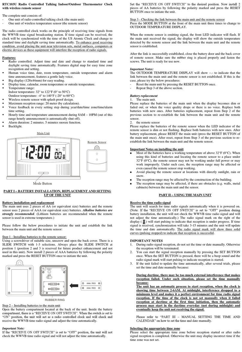
MPU-TC is a modular Master Clock and can be configured for industrial application
with up to 6 slave clock lines and up to 32 switching channels, using extension
modules. Specific to the configuration an extension enclosure is required.
The clock can be continuously synchronized using a DCF77 or GPS Antenna.
Daylight Saving Times are calculated automatically based on a user defined entry or
are defined by the DCF77 signal.
The slave clock lines outputs are polarised 24V impulses, the line type can be
defined separately for each line.
The switching channels can switch up to 230V AC signals.
Programming of the switching channels is done in multiple steps.
First the switching times of the switching channels on one day are defined in a
Dayplan. On one day only one Dayplan can be active.
The Dayplans then have to be assigned to a specific date or date period in which
they are active using the Period Assignment menu. Additionally the days of the
week in which they are active can be selected.
The Holidays menu enables the user to assign Dayplans to holidays or holiday
periods which overrule the Period Assignment Dayplan. The standard fixed and
moveable holidays are pre-programmed.

Page 5
1.2 Installation
The enclosure must be opened cautiously with a slot screwdriver. The
screwdriver
has to be pressed against the enclosure snap, when put in the
opening hole [1],
while pulling on the top of the enclosure.In the enclosure top there also is a switch
[2], which can be used to disable all switching channels.
[2] Switching Chanels
Switch
▲program (1)
▼off (0)
[1] Opening Hole

Page 6
1.3 Connections
The MPU-TC can be mounted on a support rail. A position should be considered,
where the cabling fits well through the provided opening (1).
For Wall mounting the provided 8mm dowels and the screw holes (2) should be
used.
If the optional available support rail is used, it must be checked that the enclosure is
correctly snapped onto the rail and afterwards the lock bolts (3) have to be fixed with
screws (4).
(1)
(3)
(4)
(2)
(4)
(2)
(6)

Page 7
1.4 Connection of power supply (230VAC)
The 230VDC mains supply has to be installed by qualified specialists. The wires
must not be energized during installation.
The provided supply cable with ferrite (6) has to be connected to the base circuit
board.
Live wire, neutral wire and protective earth wire need to be attached according to the
labels as follows:
•PE = Protective Earth
•N = Neutral
•L1 = Live
For comfortable mounting the plug can be removed carefully.
Live L1
Neutral N
Protective Earth PE
Fuse
T800mA

Page 8
1.5 Connection of slave clocks
Slave clock lines are also located on the base cuircuit board inside the housing. The
clocks for line 1 must be attached to the terminal with the label 1.1 1.2 and clocks
for slave clock line 2 should be connected to the terminal 2.1 2.2.
The electrical schema is presented in the following figure.
DCF+ DCF-
2.1
2.2
1.1
1.2

Page 9
1.6 Connection of DCF receiver
The DCF77 antenna needs to be plugged into the terminal with the label +DCF-.
Before attaching the antenna the MPU-TC must be taken from main supply, the
polarity of the Mattig-Schauer DCF77 Antenna does not need to be considered.
After powering the MPU-TC again, the signal quality can be checked with the
antenna symbol on the MPU-TC display, the control LED on the base cuircuit board
or the LED on the DCF antenna. All of those indications should blink in a one second
cycle.
If the LEDs blink aperiodic or permanent, then the antenna needs to be positioned
differently. To improve reception conditions please change position of the DCF
antenna as long as necessary. The DCF antenna should be mounted in a 90°angle
to the direction of Mainflingen near Frankfurt/Germany.
In case the signal reception is interfered by means of the shape or material of the
building (reinforced concrete) or due to the surroundings (high buildings, cranes, etc)
the DCF antenna should be mounted externally (facade or roof). The maximum
distance with shielded cable can be 200m.
In other cases the MPU-TC master clock can also be synchronised by GPS antenna
with output of DCF signal.
If the BMC is operated together with the Network Module, it can be synchronized to a
Network Time Server (NTP). In this case antenna input is ignored. For more details
can be found in the user manual of the Network Module.

Page 10
2 Operation
2.1 Description of the display
After powering the device the MPU-TC shows its actual Software Version for a
moment, and then it shows the start screen and is ready to operate.
Description of first line:
16
day of month
08
month
2011
year
s
summertime
w
wintertime
!
keyboard unlocked
keyboard unlocked
16
hour
22
minute
23
second
Description of second line:
Bell1
name of active dayplan
¥
DCF antenna symbol
-
symbol for impulse synchronisation
B
synchronised to network module
?
no synchronisation for more than 1 minute
!
synchronisation alarm
If a dayplan is active on that day, its name will be displayed in the second line.
Potential alarms are also displayed in the second line, like synchronisation alarm
(ALARM –SYNC!) or a short circuit on slave clock line 1 for instance (ALARM – LI1).
If the keyboard is unlocked, the actual state of the lines and switching channels can
be displayed in the second line by pressing the button
?
??
?
.
2.2 First steps
By pressing the buttons
^
^^
^
und
v
v v
v
simultaneously the keyboard is unlocked and then
the contrast of the LCD display can be adjusted in the start screen with the buttons
<
<<
<
und
>
>>
>.
..
.
To navigate through the menu points the buttons
^
^^
^
and
v
v v
v
are used. With the
buttons
>
>>
>
or
e
ee
e
the menus can be entered. The menus can also be entered by
pressing their corresponding menu number (see following table). The menus or sub
menus can be left with the
c
cc
c
or
<
<<
<
button.
16.08.2011w!16:22:23
Bell1 ¥

Page 11
3 Menu
Start Screen
1 Masterclock
11 Date
12 Time
13 Sync-Source
14 Time Zone
15 Su/Wi Source
2 Lines
21 Line Time
22 Line Offset
23 Line Type
24 Impuls/Pause
3 Relays
31 Relay Status
32 Relay Configuration
33 Relay Timer
34 Relay manual
4 Programming
41 Holidays
42 Period assignment
43 Dayplans
44 Serial Interface
5 Settings
51 Language/Sprache
52 Daylightsaving
53 Restart
54 Init Memory
55 Relay Test
6 Service
61 Power-On Time
62 Synchronisation
63 Synchronisation Quality
64 Last Synchronisation
65 Daylightsaving Switching Times
66 Supply Voltage
67 Temperature
68 Error Memory
69 Software Version

Page 12
3.1 Masterclock
3.1.1 Date
After unlocking the keyboard, navigate to Menu “1 Master lo k” and then “11
Date” using the arrow- or number-buttons as described in chapter Fehler!
Verweisquelle konnte nicht gefunden werden..
Display: 11 Date
> 16.08.2011 Th
With the button
>
>>
>
, the cursor moves to the right and the buttons
^
^^
^
and
v
vv
v
or the
number buttons allow you to select the specific value (day, month, year) of the date.
Everything is stored by pressing the button
e
ee
e
and changes are discarded with the
button Taste
<
<<
<
or
c.
c.c.
c.
If anything was changed you have to confirm your entry again
by pressing the
e
ee
e
button after the query “Save?” is displayed. However if the
changes shall be discarded you have to press the
c
cc
c
button.
3.1.2 Time
After unlocking the keyboard, navigate to Menu “1 Master lo k” and then “12
Time” using the arrow- or number-buttons as described in chapter Fehler!
Verweisquelle konnte nicht gefunden werden..
Display: 12 Time
> w 16:22:23
With the button
>
>>
>
, the cursor moves to the right and the buttons
^
^^
^
and
v
vv
v
allow you
to select sfor summertime and wfor wintertime as Daylight Saving Time setting.
With the button
>
>>
>
, the cursor moves to the right and the buttons
^
^^
^
and
v
vv
v
or the
number buttons allow you to select the specific value (hour, minute, second) of the
time.
Everything is stored by pressing the button
e
ee
e
and changes are discarded with the
button Taste
<
<<
<
or
c.
c.c.
c.
If anything was changed you have to confirm your entry again
by pressing the
e
ee
e
button after the query “Save?” is displayed. However if the
changes shall be discarded you have to press the
c
cc
c
button.

Page 13
3.1.3 Synchronisation Source
After unlocking the keyboard, navigate to Menu “1 Master lo k” and then “13
Syn -Sour e” using the arrow- or number-buttons as described in chapter Fehler!
Verweisquelle konnte nicht gefunden werden..
Display: 13 Syn -Sour e
> DCF 48h .
The MPU-TC supports synchronisation via DCF77 or GPS. With the GPS setting the
clock considers receiving GMT time instead of CET time for DCF77 and that the
summer or winter bit does not have to be exclusively set.
With the button
>
>>
>
, the cursor moves to the right and the buttons
^
^^
^
and
v
vv
v
allow you
to select DCF or GPS or IMP for synchronising the MPU-TC using polarised (pol) or
unpolarised (upol) Minute (60) or Half-Minute (30) impulses.
With the button
>
>>
>
, the cursor moves to the right and the buttons
^
^^
^
and
v
vv
v
or the
number buttons allow you to select the specific value (00 to 99 hours or no) for
synchronisation failure alarming.
This setting specifies after how many hours of not getting synchronised to an external
source (antenna or Network Module) an alarm is issued.
With the button
>
>>
>
, the cursor moves to the right and with the buttons
^
^^
^
and
v
vv
v
the
alarm acknowledgment setting can be selected. A .means that the alarm is
automatically cleared if synchronisation is re-established. If the alarm
acknowledgment option is active (symbol √ after 48h), the user has to confirm the
alarm by disabling the alarm acknowledgement option (symbol . +
e
ee
e
button) and, if
needed, re-enabling it again (symbol √ +
e
ee
e
button.
Everything is stored by pressing the button
e
ee
e
and changes are discarded with the
button Taste
<
<<
<
or
c.
c.c.
c.
If anything was changed you have to confirm your entry again
by pressing the
e
ee
e
button after the query “Save?” is displayed. However if the
changes shall be discarded you have to press the
c
cc
c
button.

Page 14
3.1.4 Time Zone
After unlocking the keyboard, navigate to Menu “1 Master lo k” and then “14
Time Zone” using the arrow- or number-buttons as described in chapter Fehler!
Verweisquelle konnte nicht gefunden werden..
Display: 14 Zeitzone
> +01:00 A
The master clock is pre-programmed to CET (i.e. GMT + 01:00). The selection can
be done in steps of 30 minutes. The offset to GMT can be programmed to be within
+12:30 to -12:30. The character behind the time offset is internationally defined. A
time zone list can be found in appendix Fehler! Verweisquelle konnte nicht
gefunden werden..
With the button
>
>>
>
, the cursor moves to the right and the buttons
^
^^
^
and
v
vv
v
allow you
to select the specific offset value for the time zone.
Everything is stored by pressing the button
e
ee
e
and changes are discarded with the
button Taste
<
<<
<
or
c.
c.c.
c.
If anything was changed you have to confirm your entry again
by pressing the
e
ee
e
button after the query “Save?” is displayed. However if the
changes shall be discarded you have to press the
c
cc
c
button.

Page 15
3.1.5 Daylight Saving Source
After unlocking the keyboard, navigate to Menu “1 Master lo k” and then “15
Su/Wi Sour e” using the arrow- or number-buttons as described in chapter Fehler!
Verweisquelle konnte nicht gefunden werden..
Display: 15 Su/Wi Sour e
> DCF
In this menu the user can select the daylight saving times switching behaviour of the
MPU-TC master clock.
DCF/user
If a DCF signal is available the switching to DST is done
according to the DST bit in the DCF packet. In case of a
poor DCF signal the DST offset is done according to the
user defined points in time (see chapter Fehler!
Verweisquelle konnte nicht gefunden werden.).
user
DST switching is done only at the user defined points in
time (see chapter Fehler! Verweisquelle konnte nicht
gefunden werden.).
DCF
Only the DCF DST bit is used for DST switching.
off
The master clock does not change to DST.
For the settings DCF and DCF/user the DST announcement bit is analysed.
After identifying 5 successive DCF packets with a set announcement bit within an
hour, a DST switch will happen at the next full hour, even if there is no DCF signal at
that point in time.
If 5 consecutive packets without the announcement bit set are received, there will be
no DST change at the next full hour, when no DCF signal is available at the moment
in time. Even if user defined settings would indicate a change for the setting
DCF/user the switching will not be done.
With the button
>
>>
>
, the cursor moves to the right and the buttons
^
^^
^
and
v
vv
v
allow you
to select the specific Summer-/ Winter-Time setting.
Everything is stored by pressing the button
e
ee
e
and changes are discarded with the
button
<
<<
<
or
c.
c.c.
c.
If anything was changed you have to confirm your entry again by
pressing the
e
ee
e
button after the query “Save?” is displayed. However if the changes
shall be discarded you have to press the
c
cc
c
button.

Page 16
3.2 Slave Clock Line Settings
After unlocking the keyboard, navigate to Menu “2 Lines” using the arrow- or
number-buttons as described in chapter Fehler! Verweisquelle konnte nicht
gefunden werden..
Display: 2 Lines 123456
> XXXXXX
Depending on the extensions to the MPU-TC, the currently available clock lines are
displayed. The line numbers are displayed in the upper line (123456) and
underneath the corresponding line state can be seen.
The state of a line can be one of the following:
X Line is off ( not active)
_ Line is on (active). A rectangle above/underneath the line
indicates positive/negative impulse output (+24V/-24V) on
the line
. Line is on (active), but waiting (for instance if the line time is
slightly ahead of the Masterclock Time and waiting is faster
than catching up)
! Short circuit or high current detected on the line
With the button
>
>>
>
, the cursor moves to the right and the slave clock line can be
selected. The selected line is displayed blinking. By pressing the button
?
??
?
, this line is
switched on/off. When the button
e
ee
e
is pressed the submenus for the specific line is
entered and the line settings can be set. These submenus are explained in the
following chapters.
3.2.1 Line Time
Display: 21 Line Time 01
> 12:03 pos
With the button
>
>>
>
, the cursor moves to the right and the buttons
^
^^
^
and
v
vv
v
or the
number buttons allow you to select the specific slave clock time (hours, minutes,
seconds – depending on the clock type) of the connected slave clocks.
With the button
>
>>
>
, the last right position can be reached and the buttons
^
^^
^
and
v
vv
v
can change the polarity of the line output. The polarity pos indicates that the first
impulse (clock starts at 12:00 postion) is +24V and with polarity neg the first impulse
is -24V.
While editing the line time the clock line is paused until the changes are submitted.
Everything is stored by pressing the button
e
ee
e
and changes are discarded with the
button
<
<<
<
or
c.
c.c.
c.
If anything was changed you have to confirm your entry again by
pressing the
e
ee
e
button after the query “Save?” is displayed. However if the changes
shall be discarded you have to press the
c
cc
c
button.

Page 17
3.2.2 Line Offset
Display: 22 Line Offset 01
> 00:00 Z
Here the offset from the line time to the master clock time can be set. The line time
will always have that offset in comparison to the master clock.
With the button
>
>>
>
you move the cursor to the right and with the buttons
^
^^
^
and
v
vv
v
the
hour offset between can be selected between -12 and +12 hours.
By pressing the button
>
>>
>
again the minute offset can be set to either 00 or 30
minutes using the buttons
^
^^
^
and
v
vv
v
. The character after the offset declares the Time
Zone specific offset.
Everything is stored by pressing the button
e
ee
e
and changes are discarded with the
button
<
<<
<
or
c.
c.c.
c.
If anything was changed you have to confirm your entry again by
pressing the
e
ee
e
button after the query “Save?” is displayed. However if the changes
shall be discarded you have to press the
c
cc
c
button.

Page 18
3.2.3 Line Type
Display: 23 LiType OR xs 01
> 1min 12h .√
The line type defines which kind of clocks is connected to the line.
The master clock will be pre-programmed to 1min (minute impulse clock), where the
clock sends a polarized 24V impulse to the clocks every full minute.
With the button
>
>>
>
you move the cursor to the right and select the type of line using
the buttons
^
^^
^
and
v
vv
v
. Supported types are seconds (1se ) / half minutes (30se ) /
minutes (1min) / Time Code mixed with minutes (TC60s) / Time Code mixed with half
minutes (TC30s) / DCF77 (DCF) / 24V on line output (DC24V).
By using the button
>
>>
>
again it can be specified if the slave clocks on the line are 12h
(analog) or 24h (digital) clocks with the buttons
^
^^
^
and
v
vv
v
.
The next option which is marked with the xin the upper line is used to set the
behaviour in case of a short circuit on the line.
It can be configured after pressing using the button
>
>>
>
once more.
As default setting (.) the output of impulses is stopped when a short circuit is
detected and automatically restarted after the short circuit is resolved.
If the √is selected here then the clock checks every second if the short circuit is
resolved and if still is not, after 60 times of checking (60 seconds), the line switches
itself off and has to be re-enabled manually.
The next option determines if the line output follows the Daylight Saving Times. The
default setting (√) lets the line follow the DST settings of the master clock. If .is
selected the line will not switch to summer time, but will keep the standard time
always.
Everything is stored by pressing the button
e
ee
e
and changes are discarded with the
button
<
<<
<
or
c.
c.c.
c.
If anything was changed you have to confirm your entry again by
pressing the
e
ee
e
button after the query “Save?” is displayed. However if the changes
shall be discarded you have to press the
c
cc
c
button.

Page 19
3.2.4 Line Impulse/Pause Duration
Display: 24 Pulse Pause 01
> 1s 1s
This menu enables the user to set the duration of the impulses on the line. The first
parameter 1s means that the impulse for the clock will have a period of 1 second.
The second 1s indicates that after the impulse there will be a minimum 1 second
pause until the next impulse is generated. For a minute impulse clock it will take 2
seconds to make up one minute if the salve clock is not already synchronised.
The line will be pre-programmed to 1s pulse duration and 1s pause duration.
For standard applications the value should be 1s 1s, for special applications the
duration of the minute pulses/pauses can vary between 1s, 2s, 5s and 10s. The
pulses/pauses for second impulse slave clocks may vary between .05s, .10s, .20s
and .30s.
With the button
>
>>
>
you move the cursor to the right and with the buttons
^
^^
^
and
v
vv
v
the
impulse/pause durations can be set.
Everything is stored by pressing the button
e
ee
e
and changes are discarded with the
button
<
<<
<
or
c.
c.c.
c.
If anything was changed you have to confirm your entry again by
pressing the
e
ee
e
button after the query “Save?” is displayed. However if the changes
shall be discarded you have to press the
c
cc
c
button.

Page 20
3.3 Relays
After unlocking the keyboard, navigate to Menu “3 Relays” using the arrow- or
number-buttons as described in chapter Fehler! Verweisquelle konnte nicht
gefunden werden..
Display: 3 Relays
>
All settings for relay switching channels can be set here.
3.3.1 Relay Status
After unlocking the keyboard, navigate to Menu “3 Relays” and then “31 Relay
Status” using the arrow- or number-buttons as described in chapter Fehler!
Verweisquelle konnte nicht gefunden werden..
After entering the submenu with the button
>
>>
>
the actual state of all relay switching
channels is displayed. The user can not configure anything in this menu, it only
shows the actual state of the relay channels.
Display: 1......2.......
3....
The above example shows a display of a MPU-TC with two 8Rel extension boards
and one 4Rel extension board. Channels 1 and 6 on relay extension board 1 (8Rel)
and channel 4 on relay extension board 2 (8Rel) are switched on, all other channels
are switched off at this moment.
Possible relay states are
on
.off
Aalarm (short circuit on a line or synchronisation alarm)
S summer – indicates active summertime
W winter - indicates wintertime
Table of contents
Popular Clock manuals by other brands

Ravencourt
Ravencourt Rosebud quick start guide

Bodet Time
Bodet Time BT 6 Series operating instructions

Oregon Scientific
Oregon Scientific PRYSMA G RRM222P User instruction

Oregon Scientific
Oregon Scientific RM602 user manual

Oregon Scientific
Oregon Scientific RM313P instruction manual

Mini Gadgets
Mini Gadgets BB2BLUETOOTHCLOCK user manual

La Crosse Technology
La Crosse Technology 404-3036BW quick start guide

Hama
Hama CWA100 operating instructions

MGA Entertainment
MGA Entertainment 403640 user guide

Simplex
Simplex Acroprint 175 Installation, operating and programming instructions

König
König KN-WS102N manual

GlobalTime Electronic
GlobalTime Electronic GTD368 Series Installation and user manual