McDonald's C602 User manual

This manual is for the exclusive use of licensees and employees of McDonald's Corporation.
©2005 McDonald's Corporation May, 2005 (Original Publication) Printed in
All Rights Reserved (Updated August, 2020 ) The United States of America
EM SD11
Warranty
Warranty information is contained in this Equipment Manual. Refer to the warranty information listed in the Limited Warranty on
Equipment and Limited Warranty on Parts sections and to the warranty classifications listed in the Parts Identification/Function
section when service is performed on your machine.
It is recommended that the operator take the necessary time to carefully read through the complete warranty information.
Thoroughly understand your warranty protection before you begin operation.
For any questions pertaining to the Taylor warranty, please contact Taylor Company, Rockton, Illinois 61072.
Soft Serve/Shake Combination Freezer
Taylor Model C602
Place this chapter in the Shakes/Desserts
section of the Equipment Manual.
Manufactured exclusively for
McDonald's®by
Taylor Company
750 N. Blackhawk Blvd.
Rockton, IL 61072
Phone: (815) 624-8333
Toll Free Number
Outside Illinois:
1 (800) 228-8309
Inside Illinois:
1 (800) 851-5639
Fax: (815) 624-8000
Table of Contents
Introduction ....................................................................................................................................................... 1
Safety................................................................................................................................................................ 1
Parts Identification/Functions............................................................................................................................ 4
Important to the Operator................................................................................................................................ 31
Daily Opening Procedures .............................................................................................................................. 34
Syrup System.................................................................................................................................................. 39
Daily Closing Procedures................................................................................................................................ 42
Scheduled Maintenance - Syrup System ........................................................................................................ 46
Syrup Topping Pump ...................................................................................................................................... 49
Manual Brush-Cleaning .................................................................................................................................. 54
Equipment Setup ............................................................................................................................................ 59
VFD Screens................................................................................................................................................... 74
Manager's Menu ............................................................................................................................................. 78
Troubleshooting Guide.................................................................................................................................... 91
Parts Replacement Schedule ....................................................................................................................... 106
Limited Warranty on Equipment.................................................................................................................... 107
Limited Warranty on Parts ............................................................................................................................ 109
Ordering/Service Information ........................................................................................................................ 112

1
INTRODUCTION
The Model C602 is a combination shake and soft serve
freezer. The soft serve side uses a 3.4 qt. (3.2 L) freezing
cylinder with a single-spout door.
The shake side has a 7 qt. (6.6 L) freezing cylinder with a
four-flavor dispensing door. The touch panel has four
flavor symbols for selecting and drawing the desired
shake flavor. When dispensing a shake, the cup is placed
on the shake cup holder below the door spout. A shake
flavor symbol is selected to automatically raise the
draw valve, allowing frozen mix and syrup to enter the
door where they are blended and dispensed as a finished
shake.
A portion control device will sense the filling of the shake
cup and automatically close the draw valve upon filling
the shake cup to the correct level. The operator also has
the ability to override the portion control and stop
dispensing the shake by pressing any of the four shake
flavor symbols. The shake draw valve can also be raised
and lowered in the Wash and Off modes by selecting any
of the four flavor symbols to enable cleaning, sanitizing,
and priming.
Shake syrup is stored in the lower front compartment.
Each syrup flavor is delivered to the dispensing door by a
peristaltic pump. Syrup can be pumped directly from
disposable plastic jugs or stainless steel tanks, or
adapted to syrup-in-bag dispensing. The proper syrup
delivery rate is achieved by calibrating each syrup flavor.
The mix is located in the mix hopper and is pumped to
the freezing cylinder by an air/mix pump.
When your machine is delivered, or if it has been in the
OFF position for more than 24 hours, disassemble the
freezer following the Manual Brush-Cleaning procedures
on page 48. Follow the Equipment Setup procedures on
page 59 to reassemble your machine.
The machine must be disassembled, cleaned, sanitized,
and lubricated at least once every 2 weeks. Syrup lines
must be cleaned and sanitized weekly.
It is recommended that these operating procedures be
followed closely to ensure correct assembly and
disassembly of the freezer.
The C602 is designed for indoor use only.
Note: Only instructions originating from the factory or its
authorized translation representative(s) are considered to
be the original set of instructions.
SAFETY
Always follow these safety precautions when operating
the freezer:
NOTICE! DO NOT operate this machine
without reading this manual. Failure to follow these
instructions may result in machine damage, poor
dispenser performance, health hazards, or personal
injury.
IMPORTANT! This machine is to be used only
by trained personnel. It is not intended for use, cleaning,
or maintenance by children or people with reduced
physical, sensory, or mental capabilities, or lack of
experience and knowledge, unless given supervision or
instruction concerning the use of the machine by a
person responsible for their safety. Children should be
supervised to ensure that they do not play with the
machine.
WARNING! Avoid injury.
•DO NOT operate the machine unless it is
properly grounded.
•DO NOT operate the machine with fuses larger
than specified on the machine's data label.
• All repairs should be performed by a Taylor
service technician.
• The main power supplies to the machine must
be disconnected prior to performing installation,
repairs, or maintenance.
•For Cord-Connected Machines: Only Taylor
service technicians or licensed electricians may
install a plug or replacement cord on the
machine.
• Machines that are permanently connected to
fixed wiring and for which leakage currents may
exceed 10 mA, particularly when disconnected
or not used for long periods, or during initial
installation, shall have protective devices to
protect against the leakage of current, such as a
GFI, installed by the authorized personnel to the
local codes.
• Stationary machines which are not equipped
2
with a power cord and a plug or another device
to disconnect the machine from the power
source must have an all-pole disconnecting
device with a contact gap of at least 0.125 in.
(3 mm) installed in the external installation.
• Supply cords used with this machine shall be
oil-resistant, sheathed flexible cable not lighter
than ordinary polychloroprene or other
equivalent synthetic elastomer-sheathed cord
(code designation 60245 IEC 57) installed with
the proper cord anchorage to relieve conductors
from strain, including twisting, at the terminals
and protect the insulation of the conductors from
abrasion.
• If the supply cord is damaged, it must be
replaced by an Taylor service technician in order
to avoid a hazard.
• Secure the supply cord ground lead to the
machine in a location where if the cord is pulled,
the main power leads will become taut before
the ground lead can break loose.
Failure to follow these instructions may result in
electrocution. Contact your local authorized Taylor
distributor for service.
IMPORTANT! An equipotential grounding lug is
provided with this machine. Some countries require the
grounding lug to be properly attached to the rear of the
frame by the authorized installer. The installation location
is marked by the equipotential bonding symbol (5021 of
IEC 60417-1) on both the removable panel and the
machine's frame.
WARNING! Avoid injury.
•DO NOT allow untrained personnel to operate
this machine.
•DO NOT operate the machine unless all service
panels and access doors are fastened with
screws.
•DO NOT remove any internal operating parts
(including, but not limited to, freezer door,
beater, or scraper blades), unless all control
switches are in the OFF position.
Failure to follow these instructions may result in severe
personal injury, especially to fingers or hands, from
hazardous moving parts.
WARNING! DO NOT attempt to draw product
or disassemble the machine during the heat treatment
cycle (if equipped). The product is hot and under extreme
pressure. Severe burns from hot product may result if this
instruction is not followed.
WARNING! This machine has many sharp
edges that can cause severe injuries.
•DO NOT put objects or fingers in the door
spout. This may contaminate the product and
cause severe personal injury from blade
contact.
•USE EXTREME CAUTION when removing the
beater assembly. The scraper blades are very
sharp.
•USE EXTREME CAUTION when handling the
cup/cone dispenser (if supplied with machine).
Two people are required to handle the cup/cone
dispenser. The appropriate type of protective
gloves must be worn and the mounting holes
must NOT be used to lift or hold the dispenser.
Failure to follow these instructions can result in personal
injury or damage to the machine.
WARNING! Only install this machine in a
location where its use and maintenance is restricted to
trained personnel. Failure to comply may result in
personal injury.
CAUTION! This machine must be placed on a
level surface. Use caution when moving the machine.
Failure to comply may cause the machine to tip over and
result in personal injury.
NOTICE! Cleaning and sanitizing schedules
are governed by your federal, state, or local regulatory
agencies and must be followed accordingly. Please refer
to the cleaning section of this manual for the proper
procedure to clean this machine.
3
CAUTION! This machine is designed to
maintain product temperature under 41°F (5C). Any
product being added to this machine must be below 41F
(5C). Failure to follow this instruction may result in
health hazards and poor machine performance.
WARNING! This machine must NOT be
installed in an area where a water jet or hose can be
used. NEVER use a water jet or hose to rinse or clean
the machine. Failure to follow this instruction may result
in electrocution.
This freezer is designed to operate indoors, under normal
ambient temperatures of 70°F to 75°F (21°C to 24°C).
The freezer has successfully performed in high ambient
temperatures of 104°F (40°C) at reduced capacities.
Do not obstruct air intake and discharge openings: 3 in.
(76 mm) minimum airspace all sides. Install the deflector
provided to prevent recirculation of warm air. Failure to
follow this instruction may cause poor freezer
performance and damage to the machine.
Do not run the machine without product. Failure to follow
this instruction can result in damage to the machine.
NOTICE all warning labels that have been attached to
the freezer to further point out safety precautions to the
operator.
Water Connections
(Water-Cooled Machines Only)
An adequate cold water supply must be provided with a
hand shutoff valve. On the underside rear of the base
pan, two 1/2 in. Iron Pipe Size (IPS) water connections
for inlet and outlet have been provided for easy hookup.
Permanently connect the machine using 1/2 in.
(12.7 mm) inside diameter water lines. (Flexible lines are
recommended, if local codes permit.) Depending on local
water conditions, it may be advisable to install a water
strainer to prevent foreign substances from clogging the
automatic water valve. There will be only one water in
and one water out connection. Do not install a hand
shutoff valve on the water out line! Water should always
flow in this order: first, through the automatic water valve;
second, through the condenser; and third, through the
outlet fitting to an open trap drain.
IMPORTANT! A backflow prevention device is
required on the incoming water connection side. Please
see the applicable national, state, and local codes for
determining the proper configuration. Water pressure to
the unit must not exceed 150 psi (1034 kPa).
HAZARD COMMUNICATION STANDARD (HCS) - The
procedure(s) in this manual include the use of
chemical products. These chemical products will be
highlighted with bold faced letters followed by the
abbreviation (HCS) in the text portion of the
procedure. See the Hazard Communication Standard
(HCS) manual for the appropriate Material Safety
Data Sheet(s) (MSDS).
This machine is made in America and has American
sizes of hardware. All metric conversions are
approximate and vary in size.
NOISE LEVEL: Airborne noise emission does not
exceed 78 dB(A) when measured at a distance of 39 in.
(1.0 m) from the surface of the machine and at a height of
63 in. (1.6 m) from the floor.
IMPORTANT! If the crossed-out wheeled-bin
symbol is affixed to this machine, it signifies that this
machine is compliant with the EU Directives as well as
other similar end-of-life legislation in effect after August
13, 2005. Therefore, it must be collected separately after
its use is completed and cannot be disposed as unsorted
municipal waste.
The user is responsible for delivering the machine to the
appropriate collection facility, as specified by your local
code.
For additional information regarding applicable local
disposal laws, please contact the municipal waste facility
and/or local authorized Taylor distributor.

4
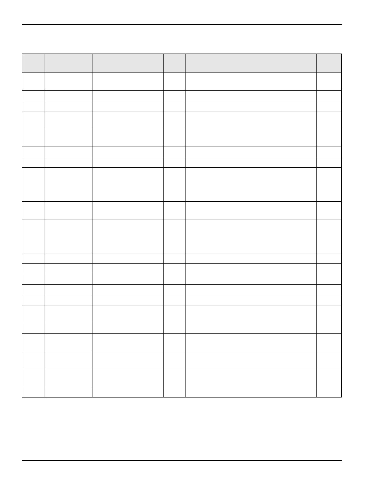
PARTS IDENTIFICATION/FUNCTIONS
Exploded View
*Items supplied by Taylor on machines manufactured prior to serial number M1080000.
Item Part No. Description Qty. Function Warr.
Class
1 X65368 Kit A.-Cover-Hopper *Single*
Black
2 Protects mix in mix hopper from debris and helps keep
temperature in the mix hopper uniform.
103
X65178 Kit A.-Cover-Hopper *Dual*
Black
* Note: If both hopper covers need to be replaced, order
X65178.
1a 045191 Label-Caution-Agitator 2 Warning label placed on each hopper cover. 000
2 X44797 Agitator Assembly 2 Stirs product in mix hopper to ensure even
temperature.
103
3 043934 Pin-Retaining Hopper Cover 2 Holds hopper cover while filling hopper with mix. 103
4 X56003 Pan-Drip-Rear 8-3/4” Long
(22.2 cm)
2 Used to catch any mix leakage from the mix pump. 103
5 066724 Panel-Rear-Upper 1 Provides access to internal components. 103
6 X48228 Guide A.-Drip Pan Mix Pump 2 Holds the mix pump drip pan in place. 103
7 055959 Panel-Rear-Lower 1 Provides access to internal components. 103
8 X56005 Pan-Drip-Side 12-3/4” Long
(32.4 cm)
2 Used to catch any mix leakage from the rear shell
bearing.
103
9 056692 Trim-Corner-Rear Right Side 1 Cosmetic trim. Seals the panels together. 103
056693 Trim-Corner-Rear Left Side 1 Cosmetic trim. Seals the panels together. 103
10 044106 Caster-4” 2 Wheels support the machine and allow easier
movement.
103
11 011694 Screw-1/4 - 20 x 3/8 10 Attaches the panels to the frame. 000
12 055950 Panel-Side Right 1 Panel provides access to internal components. 103
13 033812 Tray-Drip 1 Catches mix leakage from spout of freezer door. 103
14 033813 Shield-Splash 1 Helps prevent any mix leakage from splashing. 103
*15 042706 Lid-Syrup Jar 2 Lid for non-heated topping containers. 103
*16 036573 Jar-Syrup - Plastic Shallow 2 Holds non-heated sundae toppings. 103
*17 036574 Jar-Syrup - Stainless Shallow 2 Holds heated sundae toppings. 103
*18 033637-1 Ladle-1 oz. (30 ml.) 2 Used to dispense non-heated toppings. 103
19 035034 Pan-Drip 19-3/4” Long
(50.2 cm)
1 Used to catch any mix leakage from the rear shell
bearing.
103
20 056131 Plate-Dec 1 Touch sensor display panel on front of machine. 103
21 055957 Panel-Side Left 1 Panel provides access to internal components. 103
22 052779-3 Filter-Air 18.0 L x
13.5 H x 70 W
2 Filters dust and dirt from the main condenser. 000
23 046437 Caster-4” SWV 3/4-10 Stem
w/Brake
2 Wheels support the machine and allow easier
movement, with locks to stop movement.
103
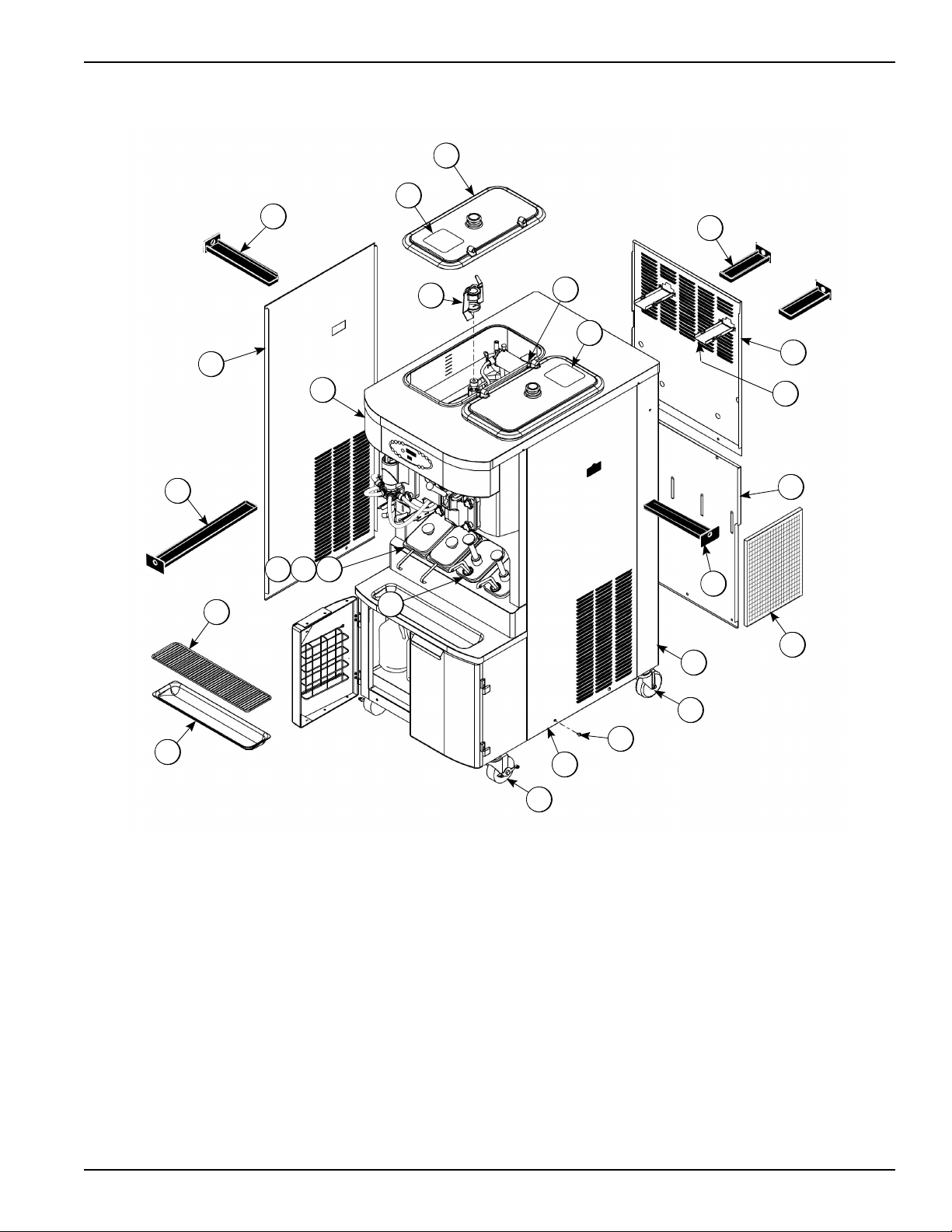
5
C602 Exploded View
Figure-1
23
12
11
10
9
22
7
6
5
4
1
1a
3
1a
8
21
19
14
181615
17
13
20
8
2
6
Front View
Not Shown
* Items supplied by Taylor on machines manufactured prior to serial number M1080000.
** Bag Syrup System (Not Shown)
† Prior to serial number K4091994, use 058630 Latch-Door-Magnetic.
Item Part No. Description Qty. Function Warr.
Class
1 055987 Stud-Nose Cone 8 Freezer door sits on these studs. Handscrews hold
door in place.
103
2 056674 Fitting-Panel Mount QD 4 Quick disconnect fitting for door syrup line. 103
3 068394 Clip-Spring Cup Holder 2 Holds the cup in place during dispensing. 103
4 X59304 Line A.-Syrup Door 4 Delivers syrup to the freezer door. Has a small slot
for thin syrup.
103
X56652 Line A.-Syrup Door 4 Delivers syrup to the freezer door. Has a large slot
for thick syrup and particulates.
103
5 064942 Shield-Pyroelectric Sensor 1 Plastic cover that protects the pyroelectric sensor. 000
†6 016121 Magnet-Catch Assy. 2 Holds the cabinet door closed. 103
7 X53353-BLU
X53353-BRN
X53353-RED
X53353-WHT
Fitting A.-Syrup Jug 1 per
tank
Transfers syrup from the syrup jug or tank to the
peristaltic pump.
103
**7 X58450 Line A.-Syrup 4 Transfers syrup from the syrup bag to the peristaltic
pump.
103
7a 053040-BLU
053040-BRN
053040-RED
053040-WHT
Cap-Ultimate Syrup 1 ea. Attachment covers for containers. 000
7b 053052-36 Hose-Beverage 4 Delivers syrup to peristaltic pump. 000
7c X53175 Tube A.-Syrup Pick Up 4 Transfers syrup from container to pump. 000
7d 053036 Ferrule-.625 ID 4 Clamps syrup hose on fitting. 000
8 X58607-SER Door A.-Cabinet 2 Insulates syrup cabinet. 103
9 059144 Basket-Door-Wire 2 Rack for storage. 103
10 051574 Screw-Adjustment 1 Adjusts the sensing eye to determine correct level of
shake.
103
11 056008 Holder-Cup Shake 1 Holds cup during dispensing. 103
*12 X53800-BRN Pump A.-Syrup- Heated
(Chocolate)
1 Dispenses heated sundae topping. 103
*13 X53800-TAN Pump A.-Syrup- Heated
(Caramel)
1 Dispenses heated sundae topping. 103
14 036435 Gasket-Drip Lip 2 Helps prevent liquid from dripping down front of
machine.
000
015971 Pin-Roll - 3/32 x 9/16 1 Secures spinner shaft in coupling assembly. 000
7
Front View
Figure-2
1
2
3
4
5
7
7a
10 11
889
7c
7b
6
12
13
14
8
Syrup Cabinet View
*Prior to serial number K4091994, use 058630 Latch-Door-Magnetic.
Figure-3
Item Part No. Description Qty. Function Warr.
Class
1 056016 Shelf-Syrup 1 Provides access to syrup pumps. 103
2 059144 Basket-Door-Wire 2 Rack for storage. 103
3 065933 Handle-Door Short 2 Handle for syrup cabinet door. 103
4 058613 Block-Hinge 4 Attaches door to syrup cabinet. 103
4a 058322 Screw 8-32 X 1/2 Socket Hd Secures block hinge.
*5 016121 Magnet-Catch Assy. 2 Holds the cabinet door closed. 103
6 052916 Pump-Peristaltic 4 Pumps syrup to freezer door. 103
7 058614 Block-Hinge 4 Attaches door to syrup cabinet. 103
8 024298 Screw-10-32 x 3/8 6 Four screws secure handle to syrup cabinet door;
two screws secure syrup pump bracket to cabinet.
000
1
2
83
8
4a
4
5
6
7
8
8
Pump Detail
8
9
Mix Pump & Tubes
*Not Shown
Figure-4
Item Part No. Description Qty. Function Warr.
Class
1 052916 Pump-Peristaltic 4 Contains rollers to propel syrup. 103
2 X54978 Kit A.-Peristaltic Pump Tube 4 Compressed by pump rollers to propel
syrup.
000
3 053036 Ferrule-.625 ID 2 ea. Clamps syrup hose on fitting. 000
4 054526 Fitting-Peristaltic Pump 2 ea. Connects line to pump tube. 103
5 024278 O-ring 1/2 OD x .070 2 ea. Provides seal between fitting and pump
tube.
000
*6 X62426-8 Line A.-Syrup 4 Provides syrup flow from pump. 103
2
5
4
3
1

10
X57028-XX Pump A. - Mix Simplified - Shake
*016132 O-ring is ordered in packages of 50 - part no. 016132-SER.
Item Part No. Description Qty. Function Warr.
Class
1 - 7 X57028-XX Pump A.-Mix Simplified Shake 1 Delivers air and mix to the freezing cylinder. 103
1 057944 Cylinder-Pump- Hopper-Shake 1 Chamber to house the piston. 103
2 X55450 Pin-Retaining 1 Secures adaptor and valve cap in cylinder. 103
3 053526 Piston-Pump-Simplified 1 Moves back and forth to intake and discharge
air and mix.
103
4 020051 O-ring 2-1/8” OD- Red 2 Provides sealed cavity inside cylinder. 000
5 056873-XX Cap-Valve 1 Provides a metered passage for air and mix.
The suffix number indicates the air orifice size.
103
6 086097 Gasket-Simplified Pump 1 Controls the flow of air and mix through the
pump (do not lubricate).
000
7 054944 Adaptor-Mix Inlet Shake-Blue 1 Provides passageway for air/mix intake and
discharge.
103
*8 016132 O-ring-11/16 OD-Red 2 Provides a seal at each end of the mix feed
tube.
000
9 044731 Pin-Cotter-Hairpin 1 Secures mix inlet tube to pump adaptor. 103
10 X41947 Shaft A.-Drive Mix Pump 1 Rotates counterclockwise to move piston back
and forth.
103
10a 039235 Crank-Drive 1 Delivers motion to piston. 103
10b 041948 Shaft-Drive 1 Delivers motion from pump motor to crank. 103
10c 008904 O-ring 1-3/4 1 Provides seal between crank and pump sleeve. 000
10d 048632 O-ring-Drive Shaft 2 Provides seal to prevent mix from leaking into
rear drip pans.
000
11 044641 Clip-Mix Pump Retainer 1 Secures air/mix pump to drive hub in mix
reservoir.
103
12 X55973 Tube A.-Feed- Hopper Shake 1 Mix and air is pumped through this tube from the
pump to the freezing cylinder.
103
13 056524 Ring-Check .120 OD 1 Releases excess pressure from freezing
cylinder back to mix reservoir.
000
14 X44761 Sleeve A.-Mix Pump 1 Guide for pump driveshaft; creates a seal to
prevent mix from leaking into back of machine.
103

11
X57028-XX Pump A. - Mix Simplified - Shake
Figure-5
13 8
8
12
9
7
6
4
2
5
41
11
10c
10a
10b
14
3
10d
10

12
X57029-XX Pump A. - Mix Simplified - Soft Serve
Item Part No. Description Qty. Function Warr.
Class
1 - 7 X57029-XX Pump A.-Mix Simplified
Soft Serve
1 Delivers air and mix to freezing cylinder. 103
1 057943 Cylinder-Pump- Hopper-Soft
Serve
1 Chamber to house the piston. 103
2 X55450 Pin-Retaining 1 Secures adaptor and valve cap in cylinder. 103
3 053526 Piston 1 Moves back and forth to intake and discharge air and
mix.
103
4 020051 O-ring 2-1/8” OD -
Red
2 Provides sealed cavity inside cylinder. 000
5 056874-XX Cap-Valve 1 Provides a metered passage for air and mix. The
suffix number indicates the air orifice size.
103
6 086097 Gasket-Simplified Pump
Valve
1 Controls the flow of air and mix through the pump (do
not lubricate).
000
7 054825 Adaptor-Mix Inlet Soft
Serve-Red
1 Provides passageway for air and mix intake and
discharge.
103
8 016132 O-ring - 11/16 OD -
Red
2 Provides a seal at each end of the mix feed. 000
9 044731 Pin-Cotter 1 Secures mix inlet tube to pump adaptor. 103
10 X41947 Shaft A.-Drive-Mix Pump -
Hopper
1 Rotates counterclockwise to move piston back and
forth.
103
10a 039235 Crank-Drive 1 Delivers motion to piston. 103
10b 041948 Shaft-Drive 1 Delivers motion from pump motor to crank. 103
10c 048632 O-ring-1/2 ID x .139W
(Drive Shaft)
2 Provides seal to prevent mix from leaking into rear
drip pans.
000
10d 008904 O-ring 1-3/4 OD x
.139W
1 Provides seal between crank and pump sleeve. 000
11 044641 Clip-Retainer-Mix Pump 1 Secures air/mix pump to drive hub in mix reservoir. 103
12 X55974 Tube A.-Feed Hopper - Soft
Serve
1 Mix and air is pumped through this tube to the
freezing cylinder.
103
13 056524 Ring-Check-Feed Tube 1 Releases excess pressure from freezing cylinder
back to mix reservoir.
000
14 X44761 Sleeve A.-Mix Pump 1 Guide for pump driveshaft; creates a seal to prevent
mix from leaking into back of machine.
103
13
X57029-XX Pump A. - Mix Simplified - Soft Serve
Figure-6
4
2
11
10d 10c
14
10b
10a
1
4
8
8
13
12
9
7
6
5
10
3
14
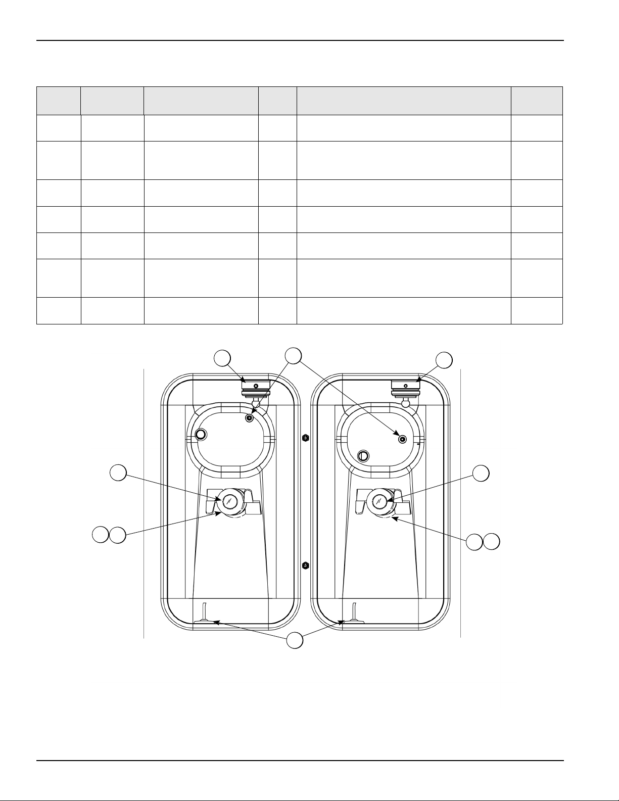
Mix Hopper - Top View
Figure-7
Item Part No. Description Qty. Function Warr.
Class
1 X44761 Sleeve A.-Mix Pump 2 Hub used to hold the air/mix pump in a locked
position.
103
2 X41348 Probe A.-Mix Out 2 Electrical device to indicate level of mix in the
hopper. Activates the Mix Out light on front of
freezer.
103
3 X51664 Housing A. Agitator
(Shake)
1 Provides magnetic force to rotate agitator
assembly.
103
3a
4a
066937 Magnet A.-Agitator-
Inner
2 Rotates the agitator paddles by magnetic force
(included with the agitator assembly).
103
4 X51661 Housing A.-Agitator -
(Soft Serve)
1 Provides magnetic force to rotate agitator
assembly.
103
5 X42077 Probe A.-Mix Low 2 Electrical device to indicate level of mix in the
hopper. Activates the Mix Low light on front of
freezer.
103
6 080826 Cap-Magnet 2 Secures the agitator paddles in place (included
with the agitator assembly).
103
5
3
6
2
11
6
44a
3a
15
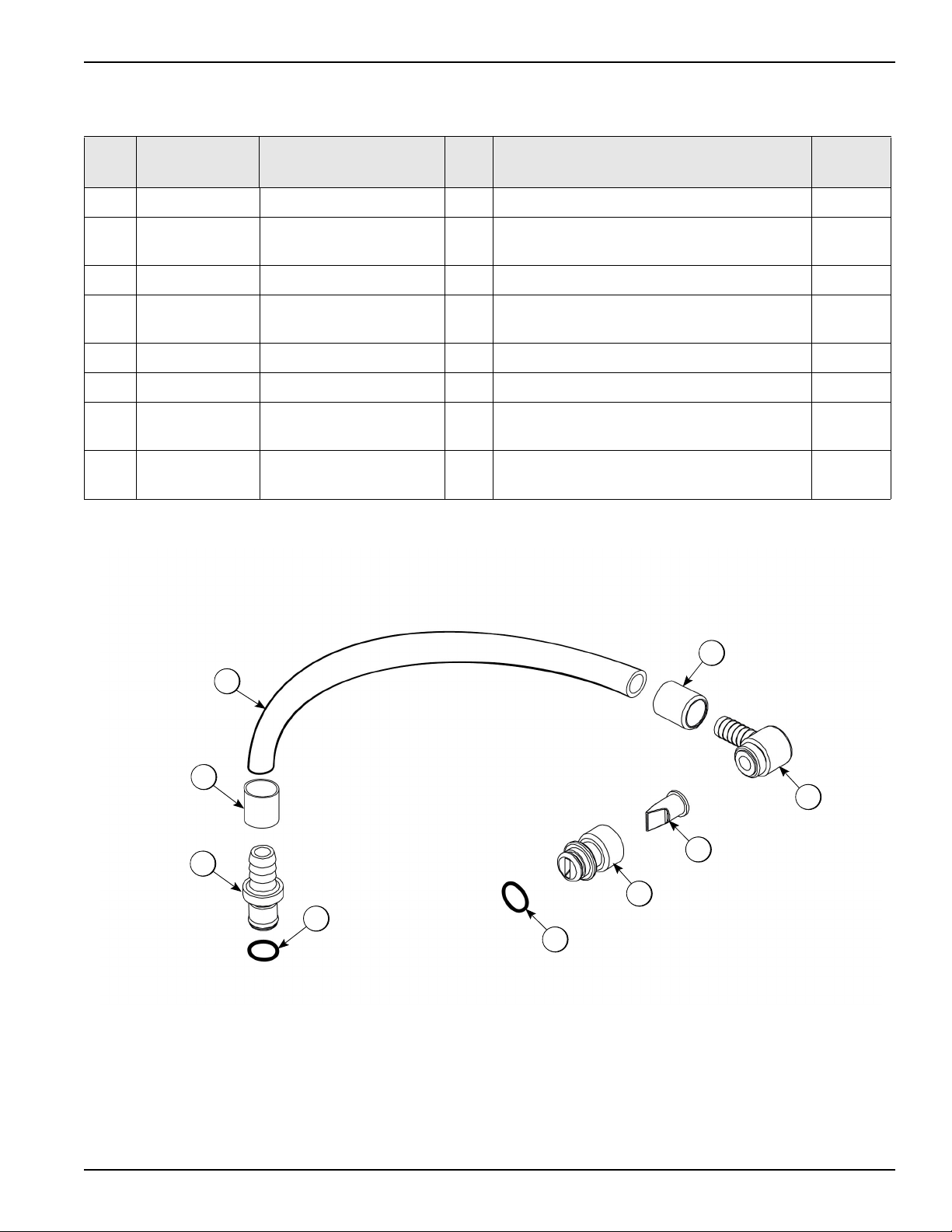
X56652 Syrup Line Assembly - Triple Thick Shake Syrup
*Not included in X56652.
Figure-8
Item Part No. Description Qty. Function Warr.
Class
1 053036 Ferrule-.625 ID 2 Clamps syrup hose on fitting. 000
2 056675 Insert-QD-CPC-3/8 Barb
Plastic
1 Connects syrup lines to front panel. 103
*3 500205 O-ring 1 Provides seal for quick disconnect fitting. 000
4 053052-9 Hose-Beverage 3/8 ID x 5/8
OD
1 Delivers syrup to freezer door (9”). 000
5 056651 Fitting-Syrup Elbow 1 Connects valve to syrup line. 103
6 500598 Valve-Check Duckbill 1 One-way valve to direct syrup flow. 000
7 056650 Fitting-Syrup Nose (Large
Slot)
1 Removable fitting allowing access to duckbill
valve.
103
8 053890 O-ring-11 mm Green (Syrup
Hole Plug)
1 Seals syrup hole plug in syrup port of freezer door. 000
8
7
6
5
1
3
2
1
4

16
X59304 Syrup Line Assembly - Thin Viscosity Syrup
*Not included in X59304.
Figure-9
Item Part No. Description Qty. Function Warr.
Class
1 029834 Ferrule-.650 ID 2 Clamps syrup hose on fitting. 000
2 056675 Insert-QD-CPC-3/8 Barb
Plastic
1 Connects syrup lines to front panel. 103
3 500205 O-ring 1 Provides seal for quick disconnect fitting. 000
4 500038-9 Tube-Vinyl 1 Delivers syrup to freezer door (9”). 000
5 056651 Fitting-Syrup Elbow 1 Connects valve to syrup line. 103
6 500598 Valve-Check Duckbill 1 One-way valve to direct syrup flow. 000
7 056649 Fitting-Syrup Nose (Small
Slot)
1 Removable fitting allowing access to duckbill
valve.
103
8 053890 O-ring-11 mm Green (Syrup
Hole Plug)
1 Seals syrup hole plug in syrup port of freezer door. 000
8
6
5
1
4
1
2
3
7
17
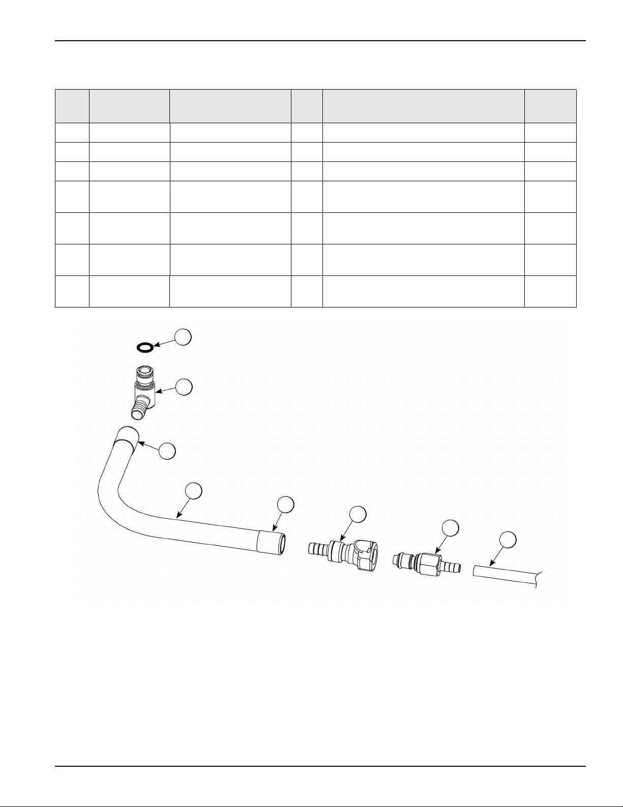
X58450 Syrup Line Assembly - Syrup-In-Bag Option
Figure-10
Item Part No. Description Qty. Function Warr.
Class
1 024278 O-ring-1/2 OD x .070 1 Provides a seal in the pump tube connection. 000
2 054526 Fitting-Male Peristaltic 1 Connects to the pump tube. 103
3 053036 Ferrule-.625 ID NP Brass 2 Secures the fitting on the hose. 000
4 058451 Coupling-QD Female 3/8
Barb
1 Quick disconnect fitting used for syrup bag
removal. Press the lever to detach.
103
5 058452 Coupling-QD Male 1/4 Barb 1 Connects the hose from the syrup bag to the
disconnect fitting.
103
6 R30314 Tube-Vinyl 3/16 ID x
1/16 Wall
1 Delivers syrup from the bag to the peristaltic
pump.
000
7 053052-36 Hose-Beverage 3/8 ID x 5/8
OD
1 Delivers syrup from the bag to the peristaltic
pump.
000
1
2
3
7
34
5
6

18
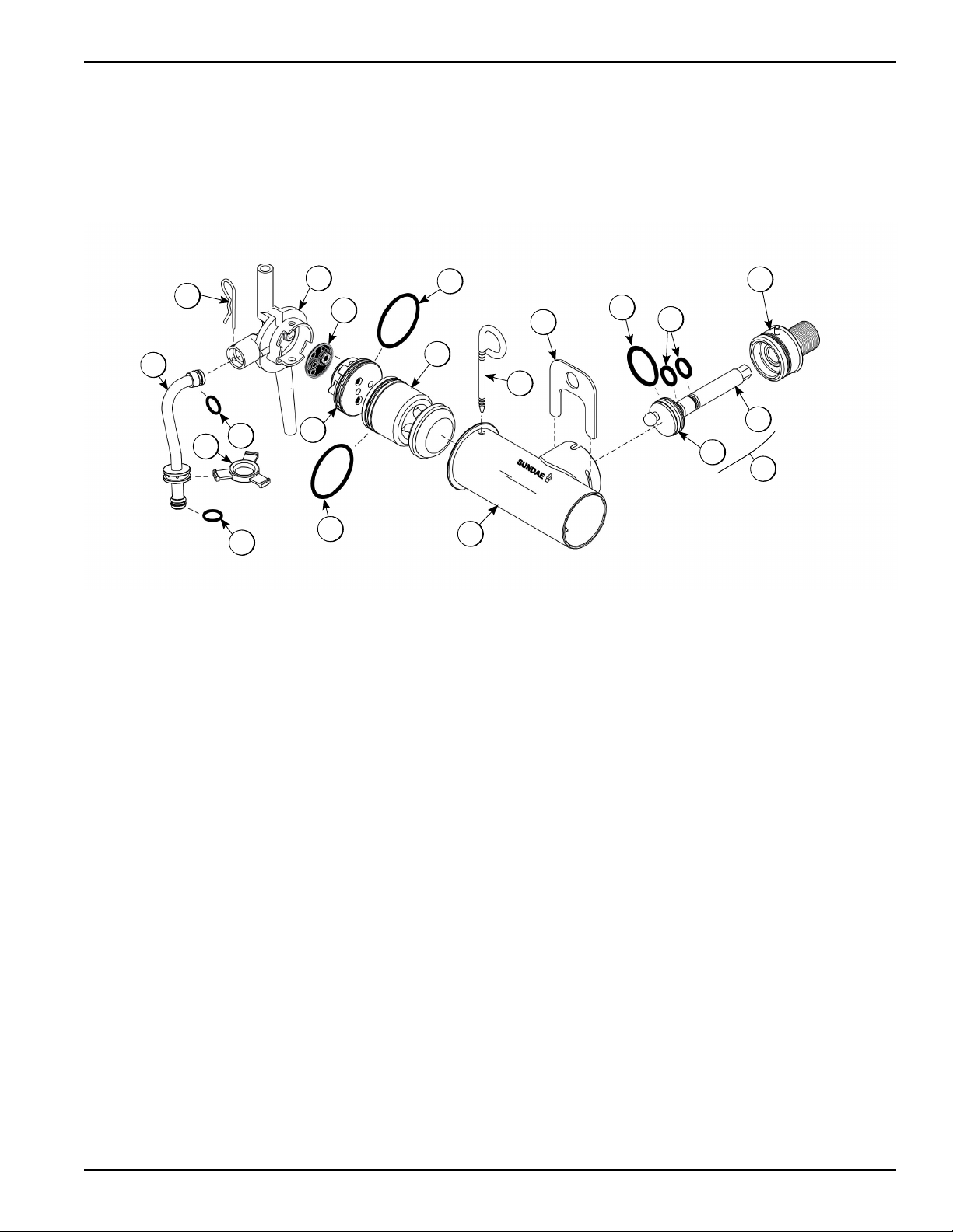
Beater Door Assembly - Shake Side
Item Part No. Description Qty. Function Warr.
Class
1 032560 Seal-Drive Shaft 1 Provides seal from product inside freezing cylinder
to internal areas of freezer.
000
2 050985 Shaft-Beater 7 Qt. Fluted
Blade
1 Connects beater assembly to gear unit. 103
3 041103 Blade-Scraper-16” 2 Scrapes frozen product off wall of freezing cylinder. 000
4 055605 Bearing-Door Front 1.390
OD
1 Allows beater assembly to turn freely in hub of
freezer door.
000
5 X50958 Beater A.-7 Qt. Fluted Blade 1 Blends air and mix inside the freezing cylinder and
provides force to dispense product.
103
6 033493 O-ring 6” - Freezer Door 1 Provides a seal between freezer door and freezing
cylinder.
000
7 X55825SER2 Door A.-Shake 1 Covers open end of freezing cylinder and provides
port for the product to be dispensed.
103
8 055989 Nut-Stud-Black 4 Tightening mechanism to secure freezer door to
freezing cylinder.
103
9 053890 O-ring -Syrup Port 11mm ID
x 2mm Green
4 Prevents leakage at syrup port plug. 000
10 053867 Plug-Syrup Port 4 Seals off syrup ports in the freezer door during the
Heat cycle.
000
11 054554 Retainer-Syrup Valve 4 Retainer pins that secure the syrup valves. 000
12 020571 O-ring - 1-1/16 OD x .139 W
(Draw Valve)
2 Provides seal for draw valve in freezer door cavity. 000
13 084696 Seal-Spinner Shaft 1 Provides a seal between draw valve and spinner
shaft.
000
14 034054 Spinner-Driven Complete 1 Helps to blend mix with syrup in freezer door cavity. 103
15 X59331 Blade A.-Spinner Aluminum-
HT
1 Blends mix with syrup in freezer door cavity. 103
16 033107 Cap- Restrictor 1 Snaps over door spout so blended product flows in a
stream.
000
17 059000 Valve A.-Draw 1 Seals off mix in freezer door cavity. When raised, the
port opens, allowing product in freezing cylinder to
be dispensed.
103
Other manuals for C602
1
This manual suits for next models
1
Table of contents


