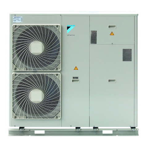
Mecaterm Arctiq User manual

Ver 1.5
Updated: 2013-10-25
MANUAL SOLO

P a g e | 2
Contents
Introduction ........................................................................................4
The heat pump ...................................................................................4
ArctiQ & ArctiQ EVI .................................................................................................................4
Aqua........................................................................................................................................5
Delivery ...............................................................................................6
Safety regulations..................................................................................................................6
Component overview..........................................................................7
ArctiQ ......................................................................................................................................7
ArctiQ EVI................................................................................................................................8
Aqua........................................................................................................................................9
Installation of ArctiQ & ArctiQ EVI ................................................... 10
Positioning........................................................................................................................... 10
Pipe installation .................................................................................................................. 13
Installation of Aqua ......................................................................... 15
Positioning........................................................................................................................... 15
Pipe installation .................................................................................................................. 15
Brine medium ..............................................................................................................................................15
Heating medium ..........................................................................................................................................19
Electrical installation....................................................................... 20
Overview .............................................................................................................................. 20
High voltage supply............................................................................................................. 21
Main supply..................................................................................................................................................21
external heat source control .......................................................................................................................21
Low voltage connections.................................................................................................... 22
Overview low voltage connections..............................................................................................................23
Control Modes ................................................................................. 24
SoloBasiC ............................................................................................................................ 24
CONTROLLING OF EXTERNAL HEAT SOURCE.............................................................................................27
SoloDigitaL .......................................................................................................................... 28

P a g e | 3
The display....................................................................................... 29
Rest mode ........................................................................................................................... 29
Actual values....................................................................................................................... 29
Setting values ..................................................................................................................... 29
Errors ................................................................................................................................... 30
Factory reset ....................................................................................................................... 30
Table - Actual values........................................................................................................... 31
Table - Set values................................................................................................................ 33
Table - Errors....................................................................................................................... 36
Quick start guide ............................................................................. 41
SoloBasiC –Set condensation .......................................................................................... 42
SoloBasiC –floating condensation ................................................................................... 43
SoloDigitaL .......................................................................................................................... 44
Service and maintainance .............................................................. 45
ArctiQ & ArctiQ EVI .............................................................................................................. 45
Manual defrost.................................................................................................................... 46
Aqua..................................................................................................................................... 47
R/T tables sensors ............................................................................................................. 48
Technical data ................................................................................. 49
ArctiQ ................................................................................................................................... 49
ArctiQ EVI............................................................................................................................. 50
Aqua..................................................................................................................................... 51
Spare part list .................................................................................. 52
ArctiQ and ArctiQ EVI .......................................................................................................... 52
Aqua..................................................................................................................................... 52
Commissioning report ..................................................................... 53
Electrical diagram ........................................................................... 54

P a g e | 4
INTRODUCTION
This manual is intended for use with the heat pump models, Mecaterm ArctiQ, ArctiQ EVI and
Aqua when used as standalone units together with arbitrary boiler/accumulator system.
When installing the heat pump together with a Mecaterm boiler, for example MasterQal, please
refer to the manual packed with the boiler unit
THE HEAT PUMP
Congratulations!
You are now the owner of a top-quality product that will reduce your electricity bills and save you
money that can be spent on much more enjoyable things.
The heat pump is manufactured by Mecaterm in Malmö, Sweden, who have extensive experience
of manufacturing heat pumps. All heat pumps, before leaving the factory, have first been tested
for functionality and technical performance. All stages of manufacturing from the plated chassis
to the finished heat pump are monitored continually to maintain quality.
The chassis of the heat pump, and all included screw and rivets, are manufactured from stainless
steel, which requires minimum maintenance and offers a long-lasting durable structure. The
components used in the pumps are supplied by renowned suppliers, based on functionality and
quality which, in turn, results in a minimum of service.
ARCTIQ&ARCTIQEVI
The ArctiQ and ArctiQ EVI models are so-called air/water heat pumps that utilise energy from the
outdoor air (indirect solar energy) and, using a cooling process, transfer heat to your boiler
system, thereby providing you with inexpensive energy.
The Mecaterm ArctiQ model is a very reliable heat pump that operates at temperatures as low as
–15ºC and produces water temperatures of up to 60ºC. The effectively sound-insulated
compressor and the optimized heat exchanger offer high operating efficiency.
The Mecaterm ArctiQ EVI model is the result of innovative solutions and technical progress
regarding compressors, which allows you to extract cheap heat from the atmosphere, even if the
outdoor temperature is as low as -25ºC.

P a g e | 5
AQUA
The Aqua model is a so-called liquid/water heat pump which means energy is extracted from a
collection pipe that is installed, for instance, in the bedrock, under the surface of the earth, in
lakes etc.
Aqua uses the same reliable components as the related ArctiQ and ArctiQ EVI models, as well as
being fitted with extra-thick sound insulation to reduce disturbing noise levels.

P a g e | 6
DELIVERY
Check the following points when your pump has been delivered and when installing the pump:
• The ArctiQ, ArctiQ EVI and Aqua pumps must be transported and stored in a vertical position.
• Remove packaging and check that the product has not been damaged in transit. Report any
transit damage to the freight agent.
• Make sure that at least one metre of space is available in front of the product for service
access.
SAFETY REGULATIONS
The following safety regulations must be observed when handling, installing and using the
product:
• Disconnect the power supply in the control box prior to carrying out any form of maintenance
and service work on the products.
• Make sure that all lifting equipment, eye bolts and other components are undamaged when
handling heat pumps fitted with eye bolts or similar items. Never stand under a product when it is
in an elevated position.
• Never compromise on safety by removing housings, hoods or similar that are screwed in place.
• Never compromise on safety by disconnecting safety equipment.
• Only authorised personnel are allowed to modify or service the product.

P a g e | 7
COMPONENT OVERVIEW
ARCTIQ
Expansion valve
Sight glass
Check valve
Filter drier/receiver
Defrost sensor
Evaporator
Primary flow temp sensor
Condensor
Air vent valve
Fan
Control unit
Return flow temp sensor
Bulb expansion valve
4-way valve
¼” schrader high pressure
¼” schrader low pressure
High pressure switch, 29bar
Low pressure switch, 0bar
Discharge gas temp sensor
Compressor

P a g e | 8
ARCTIQEVI
Defrost sensor
Main expansion valve
EVI expansion valve
Check valve
Economizer
Evaporator
Sight glass
Solenoid valve EVI
Filter drier/receiver
Fan
Control unit
Return flow temp sensor
Primary flow temp sensor
Bulb main expansion valve
4-way valve
¼” schrader high pressure
¼” schrader low pressure
High pressure switch, 31bar
Low pressure switch, 0bar
Discharge gas temp sensor
Compressor
¼” schrader EVI pressure

P a g e | 9
AQUA
Brine in temp sensor
Expansion valve
Filter drier/receiver
Compressor
Condensor
Evaporator
Variable speed charge pump
Return flow temp sensor
Drain plug condensor
Sight glass
¼” schrader low pressure
Low pressure switch, 0bar
Control unit
Primary flow temp sensor
Discharge gas temp sensor
¼” schrader high pressure
High pressure switch, 29bar
Brine circulation pump
Drain plug evaporator
Brine out temp sensor

P a g e | 10
INSTALLATION OF ARCTIQ&ARCTIQEVI
This chapter is intended for installers of the heating system. It describes how to install the ArctiQ
and ArctiQ EVI air-water heat pump models.
►Please note that the commissioning report in the end of this manual must be
filled in once the product is installed.
POSITIONING
The heat pump must be positioned outdoors and may not be installed, for instance, in a
carport or any type of outhouse. The heat pump must stand freely without a roof or
anything similar above it.
In general, make sure that the heat pump is ventilated sufficiently.
It is recommended that the heat pump be installed in close proximity to the boiler as this
reduces the length of pipes to be drawn, thereby minimising heat loss.
Even though the Mecaterm Arctic and the Arctic EVI models are well soundproofed, select an
installation location that minimises noise levels for those living in the household and for
neighbours. Note that the sound from the pump resonates more if it is placed on asphalt,
concrete, stone paving, etc., while grass, for instance, absorbs some of the noise. Contact
your local council for advice on sound levels stipulations in your area.
The heat pump automatically reduces the fan speed during the summer depending on the
break temperature set in the control panel, which in turn lowers the noise level.
It is recommended to place the heat pump on a solid base, such as garden paving,
concrete or similar material. It may be necessary, depending on where you are located, to
install the pump in a higher position to cope with large volumes of snow.
The distance from the outer wall to the heat pump must be at least 150 mm. If the pump
is to be placed at a corner, maintain a minimum distance of 300 mm to the gable-end.

P a g e | 11
Defrosting can entail a certain amount of condensation from the battery, which must be
drained off, for instance, using a gravel bed and to prevent the water from running off to
form ice on open surfaces.
Make sure that the heat pump is tilted slightly forwards to prevent water from running
down into the evaporation coil and causing problems with ice. Use the height-adjustable
legs to easily set the tilt angle.
Positioning the heat pump

P a g e | 12

P a g e | 13
PIPE INSTALLATION
As this manual is intended for the docking of heat pumps into existing boiler systems or different
types of new installations, the procedure of installing the pipework is unique for each system
involved. Certain general guidelines should be adhered to.
Copper pipes should be connected to/from the heat pump. Depending on heat pump
model the dimension will differ. For correct dimension see table below.
Nominal flow values (when using non variable speed charge pump) for each heat pump
model can be found in the table below. When using variable speed charge pump (pwm-
controlled) a desired delta temperature will be able to set and the flow will be controlled
in the software.
Pipe dimensions
Model
Size
Connection heat
pump
Minimum connection
pipe dimension
Nominal flow
ArctiQ
7,5
cu28
22mm
800l/h
10,5
1100l/h
16
28mm
1600l/h
ArctiQ EVI
10
cu28
22mm
1000l/h
14
28mm
1300l/h
20
1900l/h
Pressure drop condenser ArctiQ and ArctiQ EVI

P a g e | 14
A metal-enclosed hosing can easily be coupled between the connecting pipe and the heat
pump's condenser to prevent any vibrations/noise from being transferred to the radiator
system in the house.
Note the coupling direction of the connecting pipes/hoses on the heat pump that is
displayed on the side of the condenser as outlined in figure below.
Pipes and hoses used outdoors should be insulated with at least 15 mm of insulation,
such as armaflex or likewise. The insulation must be primed against moisture to prevent it
from becoming wet from the outside. On the inside, at least 8 mm of insulation should be
used, but the piping does not have to be insulated if you wish to heat the boiler room
instead.
In general, pipes must be fitted in such a manner that makes the system as good as self-
aerating. An aerating valve is fitted at the highest point of the condensor in the heat
pump. The aerating valve is a requirement if pipes are drawn anywhere above the level of
this valve.
Coupling direction of water to the heat pump.
Air vent valve
Condensor
Water from boiler
Water to boiler

P a g e | 15
INSTALLATION OF AQUA
This chapter is intended for installers of the heating system. It deals with the installation of the
Aqua model.
►Please note that the commissioning report found in the end of this manual must be
filled in once the product is installed.
POSITIONING
The Aqua model must be positioned indoors on a solid base, preferable on a concrete
floor.
Place the heat pump, if possible, with its back to an outer wall to prevent unnecessary
noise.
Avoid, if possible, positioning the pump close to a bedroom or other area that is sensitive
to noise.
PIPE INSTALLATION
As this manual is intended for the docking of heat pumps into existing boiler systems or different
types of new installations, the procedure of installing the pipework is unique for each system
involved.
Note! Aqua has already flexible hoses connected to the heat exchangers to prevent
vibrations why connections to the heat pump can be performed directly with
pipes.
BRINE MEDIUM
Dimensioning
The collector for earth/bedrock/ground water/lake heat, etc. is dimensioned according to
a computerised calculation program. Mecaterm can assist with this type of calculation.
Insulation
The indoor brine medium piping must be insulated with a moisture barrier material to
prevent condensation from dampness.
Note that extra insulation is required to prevent freezing or ground frost if the collector is
placed close to water piping or the ground.

P a g e | 16
Brine fluid
The brine medium should contain antifreeze medium, such as propylene glycol, to
maintain fluidity down to temperatures of -15ºC.
Collector hose
The collector hose, PEM 40 x 2.4 PN 6.3, is used as standard. Every metre of hosing holds
about 1 litre of fluid.
Air drainage
The earth heat collector should be installed in a manner that facilitates self-aerating
without any air pockets. If this is not possible, aerating valves will have to be fitted to the
highest points in the collector.
Filling valve
Pre fabricated filling valves, e.g. LK 520 Multifill 25, with integrated shut off valves/dirt
filter is recommended for easy and safe installation and filling of the brine fluid.
Expansion vessel
The expansion vessel or level tank should be installed as high as possible in the system
on incoming brine pipe (brine in), see picture below.
Safety valve
Safety valve with opening pressure of max 3 bar should be installed

P a g e | 17
1
2
3
4
5
6
6
8
7
9
1
2
3
4
5
6
6
8
7
9
Schematic connection diagram
Nr
Description
1
Brine to heat pump (in)
2
Brine from heat pump (out)
3
Filling valve (including shut off valves & dirt filter)
4
Safety valve, 3 bar
5
Level tank (expansion)
6
Shut off valve
7
Water from heat pump (primary flow)
8
Water to heat pump (return flow)
9
Arbitrary boiler/accumulator tank

P a g e | 18
Pressure drop evaporator Aqua with 30% ethylene glycol in carrier
Circulation pump curve for Aqua 5/8
Circulation pump curve for Aqua 10/12/17
Aqua 5/8
Aqua 10/12/17

P a g e | 19
HEATING MEDIUM
As this manual is intended for the docking of heat pumps into existing boiler system or different
types of new installations, the procedure of installing the pipework is unique for each system
involved. Certain general guidelines should be adhered to.
Copper piping, 22 mm or 28mm should be connected to and from the heat pump and
boiler.
Aqua has preinstalled metal-enclosed hosing on the condenser to prevent
vibrations/noise, why no further installation of hoses between tank and heat pump is
necessary.
Pipes should be insulated with 8 mm of insulation but this is not required if the
surrounding area needs to be heated.
In general, pipes must be fitted in such a manner that makes the system as good as self-
aerating.
The charge pump in the Aqua unit is a low energy variable speed circulation pump.
Depending on system settings in the control unit the flow can vary. For example, a set
constant delta temperature over the condenser can be set. In this case the software will
control the speed of the charge pump in order to achieve the desired value. (If a
Mecaterm boiler is used the speed will vary depending on the boilers need.)
Pressure drop condensor Aqua.
Aqua 5/8/10/12
Aqua 17

P a g e | 20
ELECTRICAL INSTALLATION
The electrical installation must be carried out by an authorised electrician and according to local
regulations.
OVERVIEW
Contactor compressor
12VDC power supply
230V relays
Current transformer
Soft starter NTC thermistors
Power supply connection
230V connection
Low voltage connections
Display+buttons
This manual suits for next models
2
Table of contents
Popular Heat Pump manuals by other brands
Dimplex
Dimplex SIKH 9 ME Installation and operating instructions

Carrier
Carrier 25HCS3C Product data

Waterstage
Waterstage Air to Water Operation manual
Carrier
Carrier AQUAZONE 50PTH Installation and service instructions

Bard
Bard QTEC QH303D installation instructions
Carrier
Carrier 25HPA6 installation instructions
