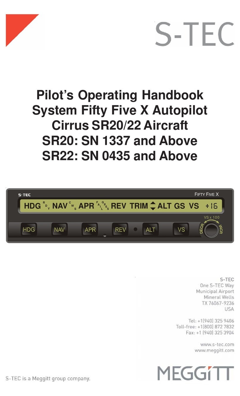
Meggitt 60-2 User manual

System60-2Autopilot
Pilot's Operating
Handbook

2nd Ed: Nov 01, 01 i
SYS 60-2 POH
List of Effective Pages * Asterisk indicates pages changed, added, or deleted by
revision.
Record of Revisions Retain this record in front of handbook. Upon receipt of a
revision, insert changes and complete table below.
Revision Number Revision Date Insertion Date/Initials
1st Edition 29 Mar 1999
2nd Edition 01 Nov 2001

ii 2nd Ed: Nov 01, 01
SYS 60-2 POH
Page Intentionally Blank

2nd Ed: Nov 01, 01 iii
SYS 60-2 POH
Table of Contents
Section Page
1.0 Introduction..........................................................................................................1-3
2.0 BlockDiagram...................................................................................................2-3
3.0 AutopilotOverview..............................................................................................3-3
3.1 System 60-2Programmer/Annunciator.............................................3-3
3.2 RollModesofOperation.......................................................................3-4
3.2.1 Heading(HDG)........................................................................3-4
3.2.2 Navigation(NAV)......................................................................3-4
3.2.3 Reverse(REV).........................................................................3-5
3.3 PitchModesofOperation.....................................................................3-5
3.3.1 VerticalSpeed(VS).................................................................3-5
3.3.2 Altitude(ALT)............................................................................3-6
3.3.3 UP...............................................................................................3-6
3.3.4 Down(DN)................................................................................3-6
4.0 Procedures..........................................................................................................4-3
4.1 Pre-FlightProcedures...........................................................................4-3
4.1.1 RollAxis.....................................................................................4-3
4.1.2 Pitch/Altitudeand VerticalSpeed.........................................4-4
4.1.3 Autotrim......................................................................................4-5
4.2 NormalOperating Procedures...........................................................4-6
4.2.1 RollAxisModes.......................................................................4-6
4.2.1.1 Heading....................................................................4-6
4.2.1.2 VORIntercept and Tracking(DG).......................4-6
4.2.1.3 VORApproach(DG)..............................................4-8
4.2.1.4 LocalizerInterceptand Tracking (DG)...............4-9
4.2.1.5 VOR/LocalizerInterceptandTracking(HSI)....4-14
4.2.1.6 DualModeIntercept..............................................4-15

iv 2nd Ed: Nov 01, 01
SYS 60-2 POH
Table of Contents
Section Page
4.2.2 PitchAxisModes.....................................................................4-20
4.2.2.1 VerticalSpeed(VS)................................................4-20
4.2.2.2 AltitudeHold(ALT).................................................4-21
4.2.2.3 Intercepting and Coupling the Glideslpoe......4-21
4.2.2.4 ManualArm/AutomaticCapture..........................4-22
4.2.2.5 ElevatorTrimIndicator..........................................4-25
4.2.2.6 OptionalAutotrim....................................................4-26
4.3 FlightDirector Operations(Optional)................................................4-26
4.3.1 SingleCue............................................................................4-26
4.3.2 TwoCue.................................................................................4-27
4.4 YawDamper/Rudder Trim System (Optional)................................4-27
5.0 Appendixes..........................................................................................................5-3
6.0 Glossary................................................................................................................6-3

2nd Ed: Nov 01, 01 v
SYS 60-2 POH
List of Figures
Figure Page
2-1 System60-2BlockDiagram............................................................................2-3
3-1 System60-2Programmer/Annunciator.........................................................3-3
4-1 DirectionalGyro..................................................................................................4-6
4-2 VOR/LOC/GPS.....................................................................................................4-8
4-3 Straight-InLocalizerApproachand Tracking(DG).....................................4-10
4-4 Procedure TurnLocalizer Approach and Tracking(DG)............................4-11
4-5 BackCourseStraight-InApproach(DG)......................................................4-12
4-6 BackCourseProcedureTurn(DG)..............................................................4-13
4-7 HorizontalSituationIndicator(HSI)...............................................................4-14
4-8 Straight-In Localizer Approach and Tracking(Optional HSI)....................4-16
4-9 Procedure Turn Localizer Approach and Tracking (Optional HSI)...........4-17
4-10 BackCourse Straight-In Approach(OptionalHSI).....................................4-18
4-11 BackCourse ProcedureTurn(Optional HSI).............................................4-19
4-12 GlideslopeInterceptandTrack......................................................................4-23
4-13 ProcedureTurnforGlideslopeApproach....................................................4-24

vi 2nd Ed: Nov 01, 01
SYS 60-2 POH
Page Intentionally Blank

2nd Ed: Nov 01, 01 1-1
SYS 60-2 POH
SECTION1
INTRODUCTION

1-2 2nd Ed: Nov 01, 01
SYS 60-2 POH
Page Intentionally Blank

2nd Ed: Nov 01, 01 1-3
SYS 60-2 POH
1.0 Introduction
The primary purpose of the System 60-2 Pilot Operating Handbook (POH)
is to provide pilots with step-by-step Functional Preflight and In-Flight Op-
erating Procedures for the installed system.
Notice
This manual should be used in conjunction with an FAA approved autopilot
Airplane Flight Manual Supplement (AFMS), Pilots Operating Handbook
Supplement (POHS) or Supplemental Flight Manual (SFM). Refer to the
specific AFMS, POHS, or SFM for your aircraft specific information and
emergency operating procedures.
If the autopilot is to be used during Instrument Flight Rules (IFR) opera-
tions, we recommend that you develop a thorough understanding of the
autopilot system, its functions, and characteristics in Visual Meteorologi-
cal Conditions (VMC). Accomplish this before undertaking an IFR flight.

1-4 2nd Ed: Nov 01, 01
SYS 60-2 POH
Page Intentionally Blank

2nd Ed: Nov 01, 01 2-1
SYS 60-2 POH
SECTION2
BLOCK DIAGRAM

2-2 2nd Ed: Nov 01, 01
SYS 60-2 POH
Page Intentionally Blank

2nd Ed: Nov 01, 01 2-3
SYS 60-2 POH
2.0 Block Diagram
Fig. 2-1. System 60-2 Block Diagram
TRIM
VOR/LOC/GPS
(SHOWN FOR REFERENCE)
AUTOPILOT DISCONNECT/
TRIM INTERRUPT SWITCH
TRIM COMMAND
SWITCH
(OPTIONAL)
TRIM SERVO
(OPTIONAL)
AUTOPILOT
MASTER SWITCH
TRIM
MASTER SWITCH
(OPTIONAL)
S
NAV
G
S
HSI
(OPTIONAL)
PITCH SERVO
TURN COORDINATOR
DIRECTIONAL GYRO
(OPTIONAL)
ABSOLUTE
PRESSURE
TRANSDUCER
PUSH HDG
ROLL SERVO
YAW SERVO
(OPTIONAL) YAW DAMPER
(OPTIONAL)
N
O
P
I
T
C
H
I
N
F
O
R
M
A
T
I
O
N
TURN COORDINATOR
2 MIN
FLIGHT DIRECTOR
(OPTIONAL)
A/P DISC
TRIM INTRPT
ROLL
COMPUTER
PITCH
COMPUTER
SELECTOR/ALERTER
(OPTIONAL)
SYSTEM 60-2 PROGRAMMER/ANNUNCIATOR

2-4 2nd Ed: Nov 01, 01
SYS 60-2 POH
Page Intentionally Blank

2nd Ed: Nov 01, 01 3-1
SYS 60-2 POH
SECTION3
AUTOPILOTOVERVIEW

3-2 2nd Ed: Nov 01, 01
SYS 60-2 POH
Page Intentionally Blank

2nd Ed: Nov 01, 01 3-3
SYS 60-2 POH
3.0 Autopilot Overview
3.1 System 60-2 Programmer/Annunciator
Fig. 3-1. System 60-2 Programmer/Annunciator
The System 60-2 Programmer/Annunciator is a rate based autopilot that
controls the roll and pitch axis of the aircraft. The autopilot's main func-
tion is to convert pilot commands to logic signals for both the roll and
pitch computers. As the pilot enters the desired mode by pressing the
mode selector switch, the computer acknowledges the selection by illu-
minating that annunciator.
The Roll Computer receives signal inputs from the turn coordinator,
DirectionalGyrooroptional Horizontal Situation Indicator (HSI), Very High
Frequency Omnidirectional Radio Range (VOR) / Localizer (LOC), Long
Range Navigation (LORAN) and the Global Positioning System (GPS)
navigation receivers. It then computes roll servo commands for stabili-
zation, turns, radio intercepts, and tracking.
The Pitch Computer receives signal inputs from the altitude pressure
transducer, internal accelerometer, glideslope deviation indicator, and
off warning flag contained in the glideslope receiver. The pitch system
provides vertical speed control and altitude hold, as well as automatic/
manual glideslope capture.
Vertical speed reference is provided by the barometric pressure trans-
ducer, while automatic and manual pitch trim sensing is provided by the
pitch servo. Drive for the elevator trim servo is provided by the pitch
computer. All modes use the transducer signal for a VS or ALT reference.

3-4 2nd Ed: Nov 01, 01
SYS 60-2 POH
3.2 Roll Modes of Operation
3.2.1 Heading(HDG)
The HDG mode provides heading preselect and turns through the use of
the heading bug on the Directional Gyro (DG) or optional Horizontal
Situation Indicator (HSI).
3.2.2 Navigation(NAV)
The NAV mode provides roll commands for automatic intercept and track-
ing of selected VOR/LOC/RNAV/LORAN/GPS navigational signals.

2nd Ed: Nov 01, 01 3-5
SYS 60-2 POH
3.2.3 Reverse (REV)
REV mode provides roll commands for automatic intercept and tracking
of the back course localizer inbound or the front course localizer out-
bound.
3.3 Pitch Modes of Operation
NOTE: Before engaging a pitch mode of operation, a roll mode must
first be engaged.
3.3.1 Vertical Speed (VS)
The VS mode provides pitch synchronization of the autopilot to the air-
craft vertical speed. To activate, press the VS mode switch. This acti-
vates the UP/DN (Down) pitch modifier switches for pilot commanded
changes of vertical speed, up to a maximum of +/- 1600 feet per minute
(rate of climb/descent).
Table of contents
Other Meggitt Autopilot System manuals
