Mekar 10MK Manual
10
INSTALLATION AND MAINTENANCE MANUAL
Manuale di installazione, uso e manutenzione
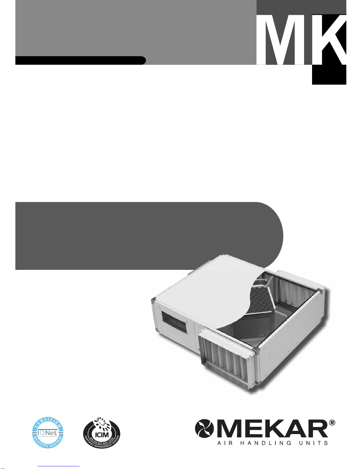
Heat recovery units
Unità di recupero calore

Manuale di installazione, uso e manutenzione
Installation and maintenance manual
mekar.it
INDICE
PREMESSA 4
AVVERTENZE 4
IDENTIFICAZIONE DELL’APPARECCHIO 4
TRASPORTO, RICEVIMENTO, MOVIMENTAZIONE 4
PRESCRIZIONI DI SICUREZZA 4
DESCRIZIONE GENERALE DELL’APPARECCHIO 4
DIMENSIONI GENERALI RECUPERATORE 5
COMPOSIZIONE PRINCIPALE 5
DATI TECNICI RECUPERATORE 6
FLUSSI D’ARIA INCROCIATI 7
NORME DI SICUREZZA 8
SCELTA DEL LUOGO PER L’INSTALLAZIONE 8
COLLEGAMENTO AI CANALI 8
COLLEGAMENTI IDRAULICI 8
Scarico condensa 8
COLLEGAMENTO EVENTUALE BATTERIA AD ACQUA
DI POST-RISCALDAMENTO 9
FREE COOLING 9
COLLEGAMENTI ELETTRICI 9
CONTROLLI AL PRIMO AVVIAMENTO 9
MANUTENZIONE 10
Manutenzione mensile 10
RICERCA DEI GUASTI 10
COSA FARE SE... 10
SMANTELLAMENTO DELL’APPARECCHIO 11
INDEX
INTRODUCTION 4
RECOMMENDATIONS 4
IDENTIFICATION OF THE UNIT 4
TRANSPORTATION, STORAGE AND HANDLING 4
SAFETY RULES 4
GENERAL DESCRIPTION OF THE UNIT 4
GENERAL DIMENSIONS 5
MAIN PARTS 5
GENERAL TECHNICAL DATA 6
CROSS-FLOW 7
SAFETY RULES 8
SELECTION OF INSTALLATION LOCATION 8
DUCT CONNECTION 8
WATER CONNECTIONS 8
Condensate drainage 8
CONNECTION OF ANY WATER RE-HEAT COIL 9
FREE COOLING 9
ELECTRICAL CONNECTIONS 9
CONTROLS AT FIRST TIME OF STARTING 9
MAINTENANCE 10
Monthly maintenance 10
TROUBLESHOOTING 10
WHAT TO DO IF... 10
DISMANTLING THE APPLIANCE 11
10 Manuale di installazione, uso e manutenzione
Installation and maintenance manual
mekar.it4
PREMESSA INTRODUCTION
AVVERTENZE RECOMMENDATIONS
- Controllare, al momento della consegna dell’apparecchio, che corrisponda a
quello indicato sul documento di trasporto.
- Verificare l’integrità degli imballi e dell’unità stessa.
- Se si dovessero riscontrare incongruenze con l’ordine, anomalie, danni o for-
nitura incompleta, indicarlo sulla bolla di consegna e avvertire tempestivamente
l’azienda.
- NON installare ne utilizzare apparecchi danneggiati.
- L’installazione dell’apparecchio deve essere effettuata da impresa abilitata che, a
fine lavoro, rilasci al proprietario la dichiarazione di conformità di installazione rea-
lizzata a regola d’arte, cioè in ottemperanza alle Norme vigenti ed alle indicazioni
fornite in questo libretto.
- È esclusa qualsiasi responsabilità per danni causati a persone, animali o cose,
da errori di installazione, di regolazione e di manutenzione o da usi impropri
- At the moment the unit is delivered, make sure that it corresponds to the one indicated
on the transport document.
- Check that the packaging and the unit are intact.
- Should there be any differences compared to the original order or any damage, anoma-
lies or incomplete supply, please report it on the delivery note and inform the company
immediately.
- Never install or use damaged appliances.
- A qualified firm must install the appliance and upon completion of work issue the owner
the declaration of conformity of installation
- with current regulations and standards and with the instructions provided in this booklet.
- Under no circumstances can the Company be held liable for damage caused to property
or injury to persons or animals due to incorrect installation, regulation and maintenance
or to misuse.
L’utilizzo di prodotti che impiegano energia elettrica ed acqua, comporta
l’osservanza di alcune regole fondamentali:
- È vietato l’uso dell’apparecchio ai bambini e alle persone inabili non assistite.
- È vietato toccare l’apparecchio se si è a piedi nudi e con parti del corpo bagnate
o umide.
- È vietato tirare, staccare, torcere i cavi elettrici fuoriuscenti dall’apparecchio, an-
che se questo è scollegato dalla rete di alimentazione elettrica.
- È vietato aprire gli sportelli di accesso alle parti interne dell’apparecchio, senza
aver prima posizionato l’interruttore generale dell’impianto su “spento”.
- È vietato modificare i dispositivi di sicurezza o di regolazione senza l’autorizza-
zione e le indicazioni del costruttore dell’apparecchio
- È vietato sedersi, salire con i piedi sull’apparecchio e/o appoggiarvi qualsiasi
tipo di oggetto.
- È vietato introdurre oggetti appuntiti attraverso le griglie di aspirazione e mandata
aria.
- È vietato disperdere, abbandonare o lasciare alla portata dei bambini il materiale
dell’imballo (cartine, graffe, sacchetti di plastica, ecc.) in quanto può essere fonte
di pericolo.
- È vietato spruzzare o gettare acqua direttamente sull’apparecchio.
- È vietato l’uso dell’apparecchio in luoghi con polveri sospese o in atmosfere
potenzialmente esplosive, in ambienti con presenza di olio in sospensione, molto
umidi o in presenza di atmosfere particolarmente aggressive.
- È vietato coprire l’apparecchio con oggetti che ostruiscano anche parzialmente
il flusso dell’aria.
- L’apparecchio funziona mediante energia elettrica alla tensione di rete (230 Vca,
50Hz). Tenete sempre presente che la tensione di rete è potenzialmente pericolo-
sa e che qualsiasi apparecchio ad essa collegato va utilizzato con attenzione. Pri-
ma di effettuare interventi sull’apparecchio, scollegatelo dalla rete elettrica (stac-
cando la spina di alimentazione o isolando la linea di alimentazione spegnendo
l’interruttore generale).
- Se l’apparecchio non viene utilizzato per lunghi periodi assicuratevi che i co-
mandi siano in posizione O (spento). Se l’apparecchio dovesse rimanere fermo
d’inverno con temperature prossime allo zero, vuotate l’impianto ed assicuratevi
che lo scambiatore dell’apparecchio sia completamente privo d’acqua per evitare
rischi di formazione di ghiaccio e conseguente rottura.
- Se l’apparecchio deve essere messo definitivamente fuori servizio, scollegatelo
in modo definitivo dalla rete elettrica.
- E’ rischioso modificare o tentare di modificare le caratteristiche di questo pro-
dotto. In ogni caso la manomissione o modifica comporta l’immediata esclusione
della garanzia.
- In caso di guasto, non cercate mai di riparare l’apparecchio da soli; rivolgetevi
a tecnici qualificati. Le riparazioni effettuate da persone non competenti possono
causare danni o incidenti.
- Tenete sempre ben pulito l’apparecchio, in particolare pulite periodicamente il
filtro aria se presente (almeno una volta al mese).
IL PRODUTTORE DECLINA OGNI RESPONSABILITÀ QUALORA NON VE-
NISSERO RISPETTATE LE ISTRUZIONI PER IL MONTAGGIO RIPORTATE IN
QUESTO MANUALE. LANON CORRETTA INSTALLAZIONE POTREBBE CAU-
SARE IL CATTIVO E/O MANCATO FUNZIONAMENTO DELL’APPARECCHIO.
POTREBBE INOLTRE ESSERE FONTE DI RISCHIO PER L’UTILIZZATORE.
Using electrically operated products connected to the water supply implies
the observance of certain basic safety rules:
- Do not allow children or unassisted handicapped persons to use the unit.
- Do not touch the unit with wet parts of the body or if barefoot.
- Do not tug, pull or twist electrical cables attached to the unit, even when discon-
nected from the electricity supply.
- Do not open the flaps giving access to the internal parts of the unit without having
first put the system on-off switch to “off”.
- Do not alter the safety or control devices without permission and instructions by
the manufacturer of the appliance.
- Do not sit, climb onto or place any objects on top of the appliance.
- Do not insert sharp pointed objects through the air intake and outlet grilles.
- Do not leave packaging material (boards, staples, plastic bags, etc.) within reach
of children, but dispose of properly since it could be a source of danger.
- Do not spray or direct water directly onto the unit.
- Do not use the unit in places with suspended dust/powder or in potentially explo-
sive atmospheres, in very damp environments or in the presence of oil in suspen-
sion or in particularly aggressive atmospheres.
- Do not cover the unit with objects that even partially obstruct the air flow.
- The unit works by electricity at mains voltage (230 Vac, 50 Hz). Always bear in
mind that mains voltage is potentially dangerous and any appliance connected to
it should be used with caution.
- Before carrying out any work on the unit, disconnect it from the electricity supply
(by pulling out the plug from the mains socket or isolating the supply line by putting
the on-off switch to OFF).
- If the unit is not to be used for long periods, make sure that the controls are in
the position 0 (off).
- If the unit is not going to be used in winter when temperatures are near to free-
zing, drain the system and ensure that the unit heat exchanger has no water in it in
order to prevent the formation of ice and consequent breakage.
- To make the unit inoperable, disconnect it totally from the electricity supply.
- It is unsafe to alter or try to alter the characteristics of this product.Any tampering
or alteration of any kind whatsoever invalidates the warranty.
- In the event of malfunction or failure, do not try to repair the unit yourself; contact
a qualified technician. Repairs carried out by incompetent persons could cause
damage or accidents.
- Always keep the unit clean. In particular periodically clean the air filter if installed
(at least once a month).
FAILURE TO COMPLY WITH THE INSTALLATION INSTRUCTIONS GIVEN IN
THIS GUIDE RELIEVES THE PRODUCER FROM ALLAND ANY LIABILITY. IN-
CORRECT INSTALLATION COULD CAUSE MALFUNCTIONING OR FAILURE
OF THE UNIT. IT COULD ALSO REPRESENT A HAZARD FOR THE USER.
Manuale di installazione, uso e manutenzione
Installation and maintenance manual
5mekar.it
TRASPORTO, RICEVIMENTO, MOVIMENTAZIONE TRASPORTATION, RECEIVING, HANDLING
PRESCRIZIONI DI SICUREZZA SAFETY RULES
L’apparecchio viene spedito racchiuso in un apposito imballo di protezione che
deve essere mantenuto integro fino al posizionamento nel luogo di installazio-
ne. La movimentazione deve essere effettuata con la massima cura mantenendo
sempre l’apparecchio nel proprio imballo originale.
TRASPORTO
Il trasporto dell’unità dev’essere effettuato in sicurezza. Il peso di ogni singola
macchina è riportato in questo manuale.
Le unità, ed i loro accessori, vengono trasportate su pallets. Gli imballi dovranno
rimanere integri fino al momento del montaggio.
Durante il trasporto:
- l’unità (e gli accessori se presenti) non deve essere sottoposta ad urti: rischio di
dannegio struttura/componenti interni;
- l’unità (e gli accessori se presenti) deve essere fissata sul piano di trasporto
tramite funi o altro mezzo che ne impedisca il movimento;
- deve essere garantita la protezione delle parti sporgenti dell’unità (attacchi idrau-
lici, scarico condensa, parti elettriche, etc.);
- non esporre l’unità (e gli accessori se presenti)agli agenti atmosferici.
STOCCAGGIO E MOVIMENTAZIONE DELL’UNITÀ
L’unità, se non installata subito, può essere immagazzinata in locali protetti dal-
le intemperie con temperature comprese tra i -20°C ed i +55°C. Al momento
dell’installazione, trasportare l’apparecchio imballato il più vicino possibile al luo-
dell’installazione. La movimentazione e l’istallazione può essere facilitata dall’uso
dell’elevatore.
The unit is delivered enclosed in special protective packaging, which must remain
intact until the unit has been located in its final place of installation.
The unit must be handled with the utmost care, keeping it in its original packaging.
TRANSPORTATION
The unit must be transported in all safety. The weight of each single appliance is
given in this guide.
The units and their accessories are transported on pallets. The packaging must not
be removed until the units are to be installed.
During transportation:
- the unit (and any accessories) must not be subjected to impact: risk of damage
to structure/internal parts;
- the unit (and any accessories) must be fixed to the surface of the means of tran-
sport by ropes or such to prevent movement;
- the projecting parts of the unit (water fittings, condensate drain, electrical parts,
etc.) must be protected;
- do not expose the unit (or any accessories) to the elements.
STORING AND HANDLING THE UNIT
The unit may be stored in rooms protected against inclement weather at a tempe-
rature between -20°C and +55°C.
When installing, put the packaged unit as near as possible to the place of installa-
tion. Handling and installation can be facilitated by using a forklift truck.
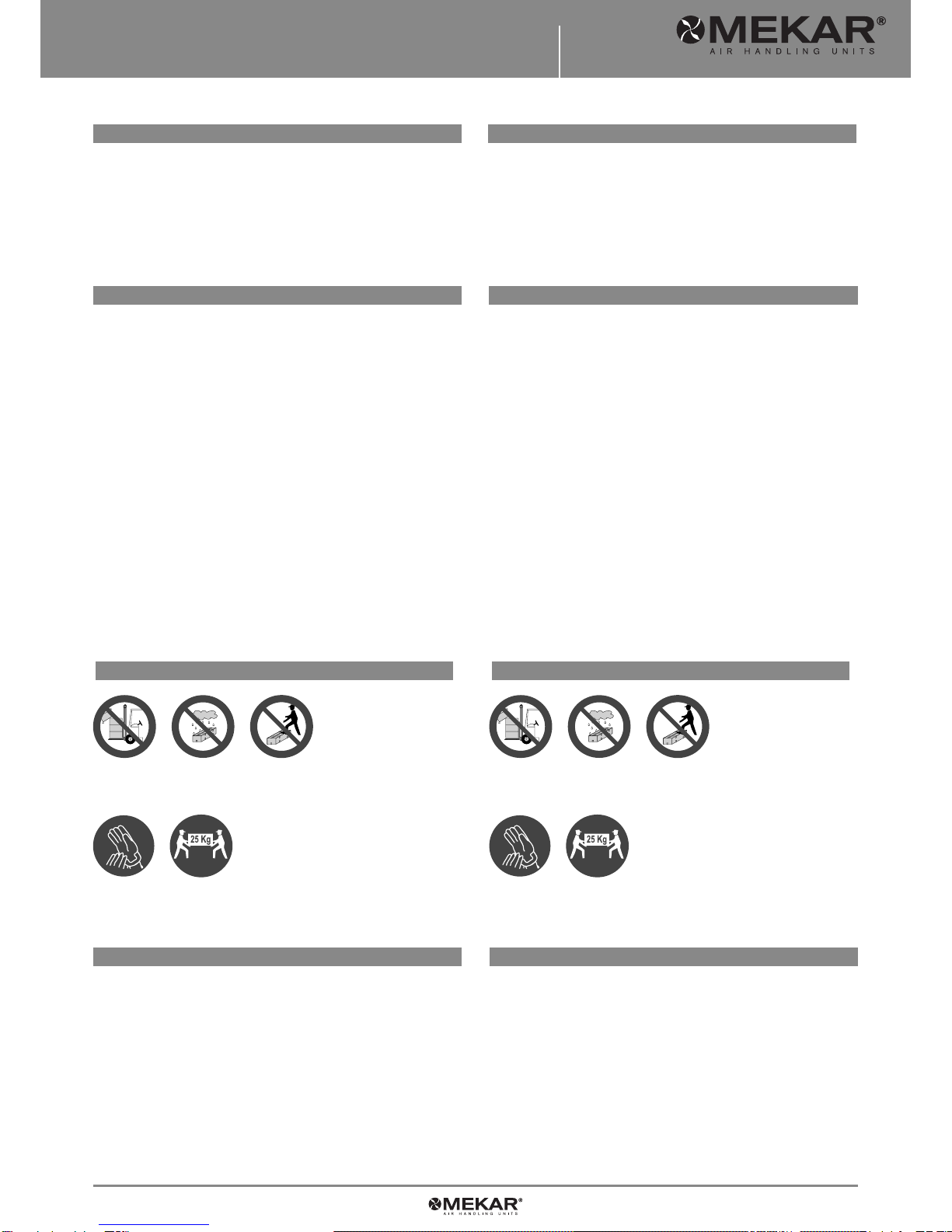
Non lasciare gli imballi sciolti durante il trasporto.
Non esporre agli agenti atmosferici.
Non calpestare.
Secure packs during transportation.
Do not expose to the elements.
Do not tread on packs.
Se l’apparecchio deve essere smontato, proteggere le mani con guanti da lavoro.
NON spostare da soli la macchina se il suo peso supera i 25 Kg. Protect hands with work gloves when dismantling the appliance.
Work in PAIRS if the applinance weighs more than 25 kg.
DESCRIZIONE GENERALE DELL’APPARECCHIO GENERAL DESCRIPTION OF THE UNIT
IDENTIFICAZIONE DELL’APPARECCHIO IDENTIFICATION OF THE UNIT
- Marchiatura “CE”; - Portata aria nominale in “m3/h”;
- Modello; - Corrente assorbita nominale in “A”;
- Potenza disponibile in “W”; - Data di produzione;
- Potenza termica recupero in “W”; - Numero lotto;
- Pressione statica in “Pa”;
- “CE” marking; - Nominal air flow “m3/h”;
- Model; - Rated absorbed current in “A”;
- Input “W”; - Date of manufacture;
- Recovery unit heat output “W”; - Lot number.
- Static pressure “Pa”;
SEZIONI VENTILANTI - Sezione ventilante di mandata e aspirazione con ventila-
tori centrifughi a doppia aspirazione pale avanti direttamente accopiati al motore
elettrico, a rotore esterno, monofase 230V/50Hz, 2 poli (per i modelli 01 e 02)
o a 4 poli (per i modelli superiori), isolamento in classe F, completi di supporti
antivibranti.
RECUPERATORE DI CALORE - Recuperatore di calore di tipo statico aria-aria a
flussi incrociati. Piastre in alluminio e telaio di contenimento in alluminio opportu-
namente sigillato. Baccinella di raccolta condensa in acciaio con tubo di scarico.
FILTRI - Filtri in poliestere di efficienza volumetrica media 86,5% Am e classe di
efficienza G3 secondo EN779.
FAN SECTIONS - Air supply and intake ventilation section with centrifugal double-
inlet forward-curved blade fans directly coupled to the single-phase external rotor
motor, 230V/50Hz,
2 poles (for the 01 and 02 models) or 4 poles (for the larger models), class F insu-
lation, complete with vibration isolation mountings.
HEAT RECOVERY UNIT - Cross-flow air-to-air static type heat recovery unit. Pla-
tes and suitably sealed retaining frame in aluminium. Steel condensate collecting
tray with drain pipe.
FILTERS - Polyester filters with average volumetric efficiency 86.5% Am and effi-
ciency class G3 to EN779.
I recuperatori di calore sono dotati di una targhetta di identificazione che riporta:
The units come with a rating plate, which shows:

10 Manuale di installazione, uso e manutenzione
Installation and maintenance manual
mekar.it6
DIMENSIONI GENERALI GENERAL DIMENSIONS
COMPONENTI PRINCIPALI MAIN PARTS
Fig. 01
Fig. 02
1234 5 67 8
1Coclea ventilatore centrifugo - Centrifugal fan scroll
2Resistenza elettrica (se presente) - Heating element (if installed)
3Ventilatore centrifugo - Centrifugal fan
4Recuperatore di calore - Heat recovery unit
5Filtro aria - Air filter
6Attacco scarico condensa Ø22 mm - Condensate drain fitting Ø 22 mm
7Angolare - Angle bar
8
Pannellatura isolata termo-acusticamente - Thermally-acoustically insulated
panelling
MOD. 01 02 03 04 05 06
Amm 290 390 390 490 490 590
Bmm 870 970 1.120 1.220 1.370 1.470
Cmm 770 770 870 870 1.020 1.175
Dmm 344 344 393 393 469 546
Emm 232 332 332 432 432 532
Fmm 224 225 230 230 300 265
Gmm 114 115 210 260 260 289
B
C
A
C
DF
E
A
G

Manuale di installazione, uso e manutenzione
Installation and maintenance manual
7mekar.it
DATI TECNICI GENERALI GENERAL TECHNICAL DATA
MOD. 01 02 03 04 05 06
Portata aria nominale* - Rated air flow* m3/h 500 750 1.250 2.000 2.500 3.000
Pressione statica massima - Max. static pressure Pa 125 200 100 150 100 105
Livello di pressione sonora - Sound pressure level dB(A) 48,4 47,9 47,2 51,3 53,4 60,0
* riferito secondo la norma ISO 3741 nella posizione di uscita aria di rinnovo con batteria di post-riscaldamento
* according to ISO 3741 referring to the fresh air outlet site with re-heating coil
Recupero termico - Heat recovery
Efficienza recupero - Recovery efficiency %464646464949
Potenza termica recupero - Heat recovery capacity kW 2,1 3,2 5,2 8,3 11,0 14,0
Temperatura uscita aria - Air outlet temperature °C 6,5 6,6 6,4 6,4 7,2 7,2
Prestazioni con temperatura aria di rinnovo di -5°C e temperatura aria espulsione di 20°C
Performance with fresh air temperature -5°C and expelled air temperature 20°C
Ventilatore - Fan
Poli - Poles n°224444
Numero velocità ventilatore - Number of fan speed n°113333
Grado di protezione - Protection rating IP IP 32 IP 32 IP 44 IP 55 IP 55 IP 10
Classe d’isolamento - Insulation class BFFFFF
Batteria post-riscaldamento - Water re-heat coil
Attacchi - Fittings Ø 1/2” 1/2” 1/2” 1/2” 3/4” 3/4”
Resa termica - Heating capacity W 4.990 8.040 12.100 19.000 22.200 27.700
Ranghi - Rows n°333333
Temperatura uscita aria - Air outlet temperature °C 45,9 44,7 42,4 39,0 39,6 39,5
Perdita di carico lato aria - Air side pressure loss Pa 20 23 32 50 47 47
Perdita di carico lato acqua - Water side pressure loss kPa 11 13 14 13 19 16
Portata aria nominale - Rated air flow m3/h 375 625 1.000 1.750 2.000 2.500
Condizioni per la batteria ad acqua di post-riscaldamento: temperatura acqua 70-60°C; temperatura aria ingresso 8°C; portata aria nominale
Water re-heat coil conditions: water temperature 70-60°C: air inlet temperature 8°C; rated air flow
Resistenza elettrica post-riscaldamento - Re-heat electric heater
Tensione nominale - Nominal current W 1.400/2.000 2.700/3.200 3.200/3.700 3.700/4.200 3.700/4.200 4.700/5.700
Voltaggio - Voltage V 230 230 230 230 230 230
Fase - Phase n°111111
Assorbimento - Input A 6,1/8,7 11,7/13,9 13,9/16,1 16,1/18,3 16,1/18,3 20,4/24,8
Temperatura uscita aria - Air outlet temperature C 17,1/21,0 19,7/21,8 16,3/17,6 14,0/14,9 12,8/13,4 13,1/14,2
Condizioni per la resistenza elettrica: temperatura aria ingresso 8°C; portata aria nominale
Re-heat electric heater conditions: inlet air temperature 8°C; rated air flow
Filtri aria - Air filters
Efficienza di filtrazione - Filtration efficiency G3 G3 G3 G3 G3 G3
Assorbimenti elettrici Max motore - Power supply
Assorbimento massimo - Maximum absorption A 2x0,95 2x1,5 2x1,5 2x3,1 2x3,0 2x5,9
Potenza disponibile all’asse - Power available for ass.y W 2x90 2x160 2x147 2x350 2x350 2x550
Alimentazione elettrica - Max motor input W/Ph/Hz 230/1/50 230/1/50 230/1/50 230/1/50 230/1/50 230/1/50
10 Manuale di installazione, uso e manutenzione
Installation and maintenance manual
mekar.it8
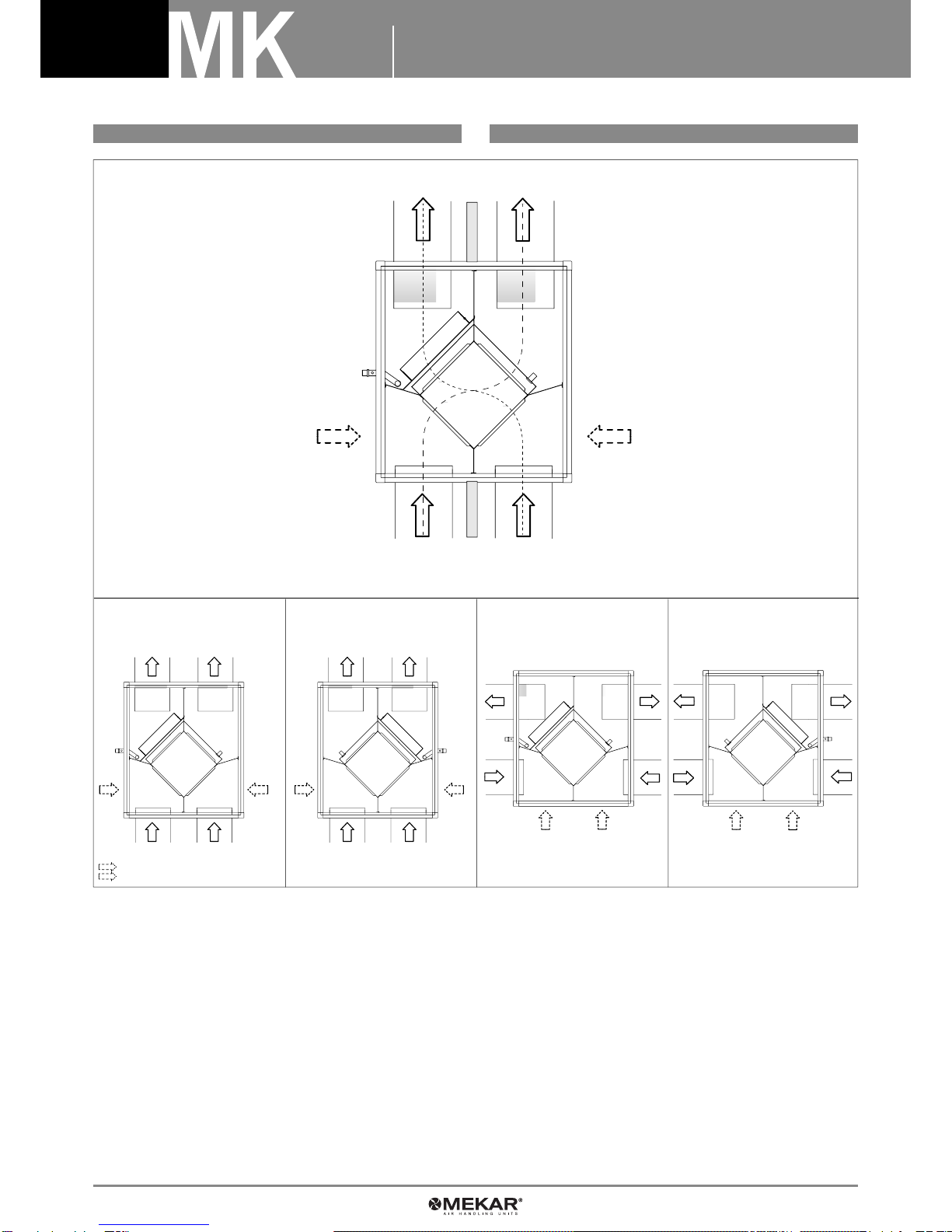
FLUSSI D’ARIA INCROCIATI CROSS FLOW
AMBIENTE INTERNO
INTERNAL AMBIENT
TIPO “A”
TYPE “A”
Immissione aria di rinnovo
Fresh air outlet
Immissione aria di rinnovo
Fresh air inlet
Immissione aria di rinnovo
Fresh air inlet
Spostando la chiusura
Shifting the closure
Espulsione dell’aria ambientale
Stale air inlet
Espulsione dell’aria ambientale
Stale air inlet
Espulsione dell’aria ambientale
Stale air outlet
TIPO “B”
TYPE “B” TIPO “C”
TYPE “C” TIPO “D”
TYPE “D”
AMBIENTE ESTERNO
EXTERNAL AMBIENT
Fig. 03

Manuale di installazione, uso e manutenzione
Installation and maintenance manual
9mekar.it
NORME DI SICUREZZA SAFETY RULES
SCELTA DEL LUOGO PER L’INSTALLAZIONE SELECTION OF INSTALLATION LOCATION
Il Produttore declina qualsiasi responsabilità per l’inosservanza delle Nor-
me di sicurezza e di prevenzione di seguito riportate.
Declina inoltre ogni responsabilità per danni causati dall’uso improprio
dell’apparecchio e/o da modifiche eseguite senza autorizzazione.
- L’installazione deve essere effettuata da personale qualificato.
- Durante l’installazione usare un abbigliamento consono (antinfortunistico)come
indicato nelle normative.
- Durante l’installazione operare in sicurezza in un ambiente libero da impedimenti
e pulito.
- Rispettate le leggi in vigore nel Paese in cui viene installato l’apparecchio rela-
tivamente all’uso ed allo smaltimento dell’imballo e dei prodotti impiegati per la
pulizia e la manutenzione della macchina.
- Evitare di toccare le parti in movimento dell’apparecchio.
- Prima di accendere l’apparecchio controllare l’integrità dei vari componenti.
- Non procedere con la manutenzione o la pulizia se prima non è stata disinserita
l’alimentazione elettrica.
- La manutenzione e sostituzione di parti danneggiate o usurate dev’essere ese-
guita unicamente da personale specializzato.
- In caso di smantellamento dell’apparecchio, attenersi alle normative vigenti in
materia.
NOTA BENE: l’installatore e l’utilizzatore durante l’uso dell’apparecchio de-
vono considerare e rimediare a qualsiasi rischio connesso con l’impianto.
Ad esempio i rischi derivanti da ingresso di corpi estranei o convogliamento
di gas infiammabili o tossici ad alta temperatura.
Failure to comply with the safety and prevention rules given below relieves
the Manufacturer from all and any liability.
Neither can the Manufacturer be held responsible for damage caused by
misuse of the appliance or by unauthorised alterations.
- Installation must be carried out by qualified personnel.
- Wear suitable (safety) clothing during installation, as recommended by applica-
ble regulations and legislation.
- During installation, work in safety by ensuring the environment is free from ob-
stacles and clean.
- Comply with the laws in force in the country in which the appliance is being in-
stalled, with regard to use and disposal of the packaging and of the products used
for cleaning and maintenance of the appliance.
- Avoid touching moving appliance parts.
- Check that the various parts are intact before switching on the appliance.
- Do not proceed with maintenance or cleaning without having first cut off the
power supply to the appliance.
- Damaged or worn parts must be maintained or replaced solely by specialised
personnel.
- When disposing of the appliance, abide by current applicable regulations and
legislation.
NOTE: when using the appliance the installer and user must consider and
remedy any risk connected with the system. For example, risks due to the
ingress of foreign matter or the conveying of inflammable or toxic gases at
high temperature.
AVVERTENZE!
- Installare l’unita di recupero calore EBF su di un soffitto solido, non soggetto a
vibrazioni, in grado di sopportare il peso della macchina
- È consigliata l’installazione antivibranti in gomma (particolare fig. 4)
- Le aperture di ripresa e di mandata dell’aria non devono essere ostruite; l’aria
deve poter circolare liberamente.
- Non installare l’unità vicino a fonti di calore, vapore o gas infiammabili.
- Installare l’unita di recupero calore EBF vicino ad una presa elettrica o con un
collegamento dedicato.
- Installare la macchina dove sia facile realizzare lo scarico della condensa.
- Controllare periodicamente il funzionamento della macchina e lasciare attorno
ad essa gli spazi necessari.
- Installare l’unita di recupero calore EBF in modo che il filtro sia facilmente ac-
cessibile.
- Non installare la macchina in ambienti in cui siano presenti sostanze acide ag-
gressive o corrosive: rischio di danneggiamento irreparabile dell’unità e dei suoi
accessori.
Scegliere un luogo per l’installazione in maniera tale che attorno alla macchina vi
siano spazi adatti per l’installazione e la successiva manutenzione. In vicinanza
dell’unità, le canalizzazioni non devono presentare bruschi raccordi o deviazioni.
Verificare che l’installazione non interferisca con l’impianto elettrico o idraulico
già esistente.
Determinare la posizione e la dimensione del foro sul soffitto.
Scegliere la posizione finale dell’unità nel soffitto.
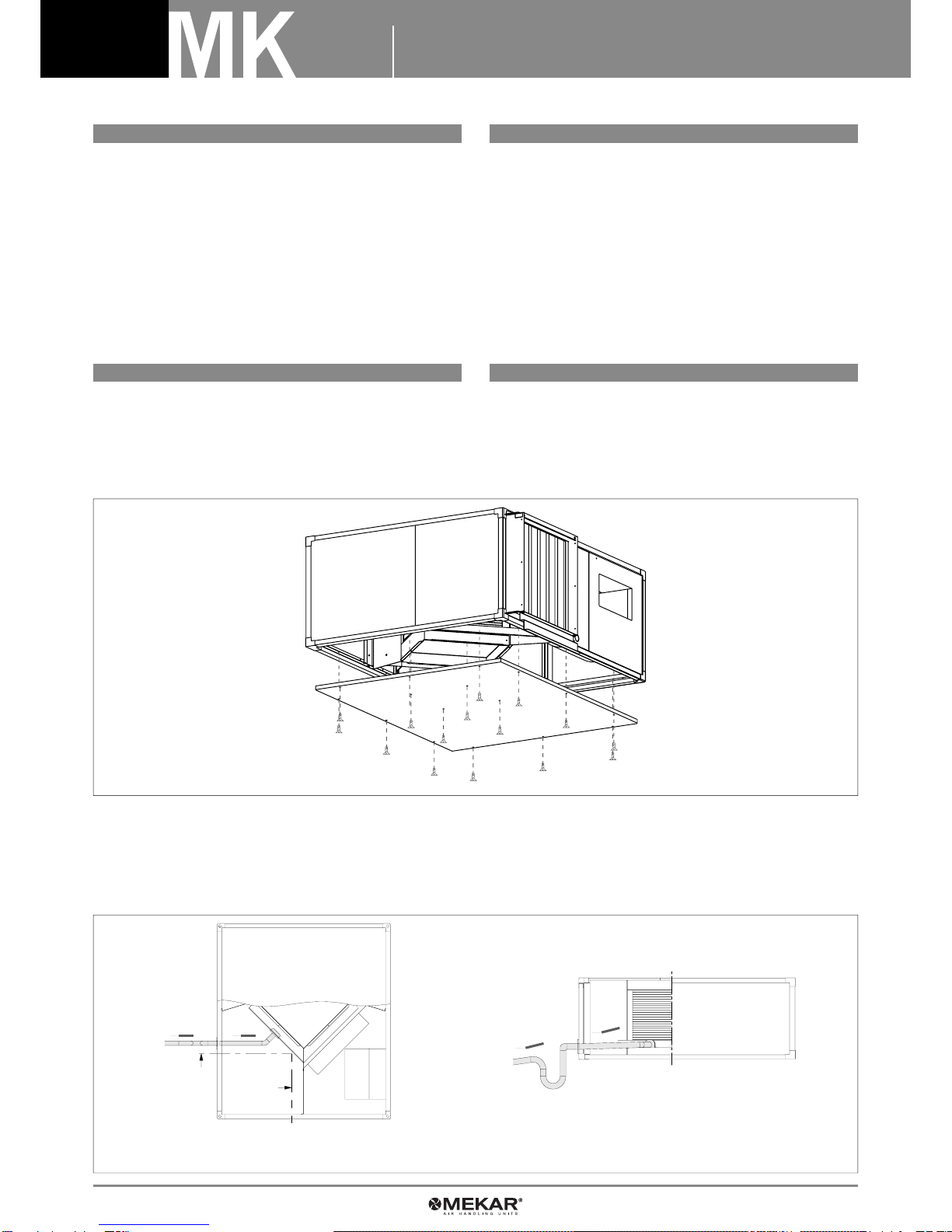
Per il fissaggio dell’unità al soffitto, utilizzare della barra filettata con dei tasselli
adeguati come illustrato nella figura 4 (materiale non incluso nella fornitura). É
consigliato l’utilizzo di barre di sostegno supplementari.
NOTA: montare l’unità inclinata di 3 mm verso la scarico condensa per favo-
rire il deflusso della condensa in modo regolare.
RECOMMENDATIONS!
- The unit must be installed in a solid and vibration-free ceiling able to support
the weight.
- The installation of rubber vibration isolation mountings is recommended (part Fig. 4).
- There must be no obstruction of the air flow into and out of the unit; the air must
be able to circulate freely.
- Do not install the unit near sources of heat, steam or inflammable gases.
- Install the unit near an electric socket or connect it directly to the power supply.
- The selected place should allow easy drainage of the condensate.
- Periodically check appliance operation and leave sufficient space around the
appliance.
- Install the unit so that the filter is easily accessible.
- Do not install the appliance in environments where aggressive or corrosive acid
substances are present: risk of irreparable damage to the unit and its accessories.
Choose a place for installation where there is sufficient space to carry out instal-
lation work and subsequent maintenance. Ductwork near the unit must not have
sharp bends or branches.
Make sure that the installation does not interfere with existing electric wiring or
plumbing. Establish the position and size of the hole in the ceiling.
Select the final position of the unit in the ceiling.
Use the threaded bar with suitable screw anchors to fix the unit to the ceiling, as
shown in figure 4 (material not included in the supply). The use of supplementary
supporting bars is recommended.
NOTE: install the unit with an inclination of 3 mm towards the condensate
drain outlet to ensure a regular flow of condensate.
Fig. 04
È consigliato
l’utilizzo di barre
di sostegno
supplementari!
Antivibrante
in gomma
The use of
supplementary
supporting bars is
recommended! Rubber
anti-vibration
10 Manuale di installazione, uso e manutenzione
Installation and maintenance manual
mekar.it10
Fig. 05
COLLEGAMENTO AI CANALI DUCT CONNECTION
COLLEGAMENTI IDRAULICI WATER CONNECTIONS
IMPORTANTE! È VIETATO METTERE IN FUNZIONE L’UNITÀ SE LE BOCCHE
DEI VENTILATORI NON SIANO STATE CANALIZZATE O PROTETTE CON
RETE ANTINFORTUNISTICA A NORMA UNI 9219 E SUCCESSIVE!
I canali devono essere dimensionati in funzione dell’impianto e delle caratteristi-
che aerauliche dei ventilatori dell’unità. Un errato calcolo delle condutture di cana-
lizzazione può provocare il malfunzionamento (es. perdita di potenza) dell’appa-
recchio o l’intervento di eventuali
dispositivi presenti nell’impianto. Per evitare di trasmettere le eventuali vibrazioni
della macchina in ambiente, è consigliato l’uso di giunti anti-vibranti fra le bocche
ventilanti ed i canali. Deve inoltre essere garantita la continuità elettrica fra ca-
nale e macchina tramite un cavo di terra. Per evitare la formazione di condensa
ed attenuare il livello di rumorosità, è consiogliato utilizzare delle canalizzazioni
coibentate.
IMPORTANT! UNDER NO CIRCUMSTANCES SWITCH THE UNIT ON IF THE
FAN OUTLETS HAVE NOT BEEN DUCTED OR PROTECTED WITH SAFETY
MESH TO UNI 9219 AND SUBSEQUENT STANDARDS!
The ducts must be sized in relation to the system and the airflow characteristics of
the fans of the unit. An incorrect calculation of duct size could cause malfunction
(e.g. loss of pressure) of the appliance or the activation of any safety devices in-
stalled in the system. To prevent the transmission of any vibration of the appliance
to the surroundings, it is advisable to use vibration isolation joints between the fan
outlets and the ducts.
Electrical continuity between duct and appliance must also be guaranteed by me-
ans of an earth wire. To prevent the formation of condensation and reduce the
noise level, it is advisable to use lagged ducts.
Il collegamento delle tubazioni idrauliche è un operazione che se non eseguito a
regola d’arte da personale specializzato può compromettere il buon funzionamen-
to dell’impianto o causare danni irreparabili all’apparecchio.
SCARICO CONDENSA
La bacinella raccolta condensa delle unità di recupero calore è in lamiera zincata
con uno scarico da 20 mm. Per il controllo e la manutenzione di tale bacinella
togliere le viti nella parte inferiore dell’apparecchio.
The water pipes must be connected in a workmanlike manner by specialised in-
stallers, otherwise proper operation of the system could be jeopardised and irre-
parable damage caused to the appliance.
CONDENSATE DRAINAGE
The condensate collecting tray of the heat recovery units is in galvanised plate and
has a drain pipe of 20 mm. To check and maintain this tray, remove the screws
from the lower part of the appliance.
Per una buona installazione ed un corretto funzionamento, si consiglia:
- la previsione di un sifone, per prevenire l’insorgere di cattivi odori, completo di
tappo per la pulizia nella parte bassa (nel caso non sia possibile, deve permettere
una facile manutenzione e pulizia);
- il tubo per lo scarico della condensa con pendenza verso l’esterno ed il più corto
possibile. Non deve inoltre avere curve a gomito troppo strette o ostruzioni di qual-
siasi tipo o provocare sollecitazioni sull’attacco all’unità;
For good installation and correct operation, the following are recommended:
- installation of a trap, to prevent unpleasant odours rising, complete with plug for
cleaning in the lower part (if this is impossible, regular maintenance and cleaning
must be facilitated);
- the condensate drain pipe must slope down towards the exterior and be as short
as possible. It must not have sharp bends or be obstructed in any way or put stress
on the unit fitting;
Fig. 06
VISTA IN PIANTA
PLAN VIEW VISTA IN SEZIONE
SECTION VIEW
Manuale di installazione, uso e manutenzione
Installation and maintenance manual
11mekar.it
Fig. 07
Fig. 08
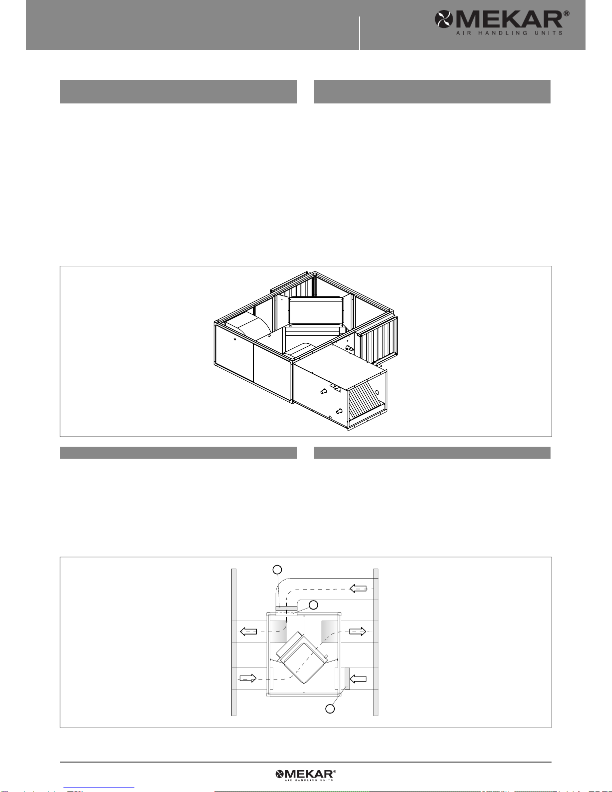
FREE COOLING FREE COOLING
COLLEGAMENTO EVENTUALE BATTERIAAD
ACQUA DI POST-RISCALDAMENTO CONNECTION OF ANY WATER RE-HEAT COIL
La modalità free-cooling prevede che l’aria viziata, proveniente dall’ambiente non
non venga espulsa passando attraverso il recuperatore, ma uscendo direttamente
all’esterno passando per un canale collegato alla bocca 2 (è necessario ordinare
uno speciale pannello completo del foro).
L’aria di rinnovo passa attraverso il filtro ed il recuperatore senza scambi di ca-
lore.
Per utilizzare la modalità free-cooling bisogna quindi costruire una canalizzazione
da unire alla bocca e predisporre 2 due serrande: la serranda 1 deve essere aperta
e la serranda 3 deve essere chiusa (vedi figura 08).
The free-cooling mode is used so that stale air coming from the room is not expel-
led through the recovery unit,
but passes directly to the exterior through a duct connected to outlet 2 (a special
panel with hole must be ordered).
The incoming fresh air passes through the filter and recovery unit without any
exchanges of heat.
To use the free-cooling mode a duct must be connected to the outlet and two dam-
pers fitted: damper 1 must be open and damper 3 must be closed (see Fig. 08).
- La batteria post-riscaldamento (se presente) ha attacchi maschio da 1/2” (filet-
tatura gas).
- Fissare i tubi di alimentazione usando chiave-controchiave;
- Sull’unità è segnalata con un’etichetta l’attacco di entrata e quello di uscita
dell’acqua;
- In caso di estrazione della batteria post-riscaldamento, non devono esserci osta-
coli: si consiglia quindi di semplificare il percorso delle tubazioni;
- Coibentare le tubazioni che arrivano alla batteria per evitare la possibile forma-
zione di condensa;
- Staffare adeguatamente le tubazioni in maniera da non pesare sulla batteria
post-riscaldamento o sull’unità;
- È consigliabile installare un dispositivo antigelo (accessorio)
- È consigliabile installare valvole di intercettazione per isolare la batteria incaso di
manutenzione o riparazioni;
- Nel caso l’unità debba rimanere fuori servizio per un lungo periodo, specialmente
nelle zone con clima molto rigido, si consiglia di svuotare l’impianto.
- The re-heat coil (if installed) has ½” male fittings (gas thread).
- Fix the supply pipes using wrench-counter wrench;
- The water inlet and outlet fittings are marked on the unit with a label;
- There must be no obstacles to removing the re-heat coil; it is therefore recom-
mended that the pipework route be simple;
- Lag the pipes leading to the coil to prevent any formation of condensation;
- Suitably support and clamp the pipework so that it does not weigh on the re-heat
coil or on the unit;
- It is advisable to install a frost protection device (accessory);
- It is advisable to install shutoff valves to isolate the coil during maintenance or
repair;
- If the unit is not going to be used for long periods, especially in very cold areas, it
is advisable to drain the system.
AMBIENTE ESTERNO
EXTERNAL AMBIENT
Immissione aria di rinnovo
Fresh air inlet
Espulsione
dell’aria
viziata
Stale air
outlet
AMBIENTE INTERNO
INTERNAL AMBIENT
2
3
1

10 Manuale di installazione, uso e manutenzione
Installation and maintenance manual
mekar.it12
COLLEGAMENTI ELETTRICI ELECTRICAL CONNECTIONS
CONTROLLI AL PRIMO AVVIAMENTO CONTROLS AT FIRST TIME OF STARTING
1) Inserire il cavo di connessione nella morsettiera saldamente. L’inserimento er-
rato potrebbe essere causa di corto circuito o incendio.
2) Assicurarsi di collegare il cavo di terra
3) Eseguire il cablaggio in conformitò con le normative in modo che l’unità possa
funzionare correttamente.
4) Prima di allacciare la corrente, assicurarsi che il voltaggio sia nel limite di po-
tenza di esercizio ± 10%.
5) Usare sempre una linea indipendente.
6) Il cavo non deve avere giunzioni.
7) Tutte le unità vanno adeguamente fornite di messa a terra così che l’utente
possa operare in sicurezza.
8) La capacità della fonte di energia deve essere la somma della corrente dell’uni-
tà e quella delle altre apparecchiature elettriche utilizzate. Quando la capacità di
servizio della corrente è insufficiente, bisogna procedere all’adeguamento della
stessa.
1) Insert the connecting cable firmly into the terminal block. Incorrect insertion
could cause a short circuit or fire.
2) Ensure that the earth wire is connected.
3) Carry out the wiring in conformity with regulations to ensure correct unit ope-
ration.
4) Before connecting to the mains electricity supply, make sure that the voltage is
within the working power limit ± 10%.
5) Always use an independent line.
6) The cable must not have joints.
7) All the units must be suitably earthed so that the user may operate in all safety.
8) The capacity of the electrical system must be sufficient for powering the unit and
other electrical appliances commonly used.
Whenever the supply current capacity is insufficient, it must be suitably adapted.
- Controllare il corretto fissaggio a soffitto e delle eventuali barre di sostegno au-
siliarie;
- Verificare l’esatto posizionamento dei pannelli;
- Assicurarsi che nella eventuale batteria ad acqua post-riscaldamento non sia
presente dell’aria (in caso contrario agire sulla valvolina di sfiato);
- Controllare che il cavo di terra per l’unità sia stato collegato;
- Controllare che i cavi di terra per le parti elettriche siano stati collegati;
-Assicurarsi che i tubi per le eventuali batterie ad acqua post-riscaldamento siano
stati adeguatamente isolati;
- Assicurarsi che i canali siano collegati all’unità.
- Check that the unit is correctly fixed to the ceiling and also any supplementary
supporting bars;
- Check the precise position of the panels;
- Ensure that there is no air in any water re-heat coil (if there is, bleed through the
air valve);
- Check that the unit earth wire has been connected;
- Check that the earth wires for the electrical parts have been connected;
- Ensure that the pipes for any water re-heat coils have been suitably lagged;
- Ensure that the ducts are connected to the unit.
MANUTENZIONE MAINTENANCE
ATTENZIONE!
Prima di eseguire qualsiasi intervento di pulizia o manutenzione, staccare
l’apparecchio dalla rete elettrica! Non utilizzate acqua per la pulizia per nes-
sun motivo!
- É dovere dell’utilizzatore far eseguire periodicamente tutte le operazioni di ma-
nutenzione;
- Le operazioni di manutenzione possono essere eseguite SOLO da personale
qualificato;
- In caso di smontaggio delle parti è necessario proteggere le mani con guanti
da lavoro.
MANUTENZIONE MENSILE
A) Pulizia del filtro
1) Svitare le 2 viti di fissaggio e togliere la placca porta-filtro;
2) Estrarre il setto filtrante.
CAUTION!
Before carrying out any cleaning or maintenance work, disconnect the unit
from the mains electricity supply! Under no circumstances use water for
cleaning!
- It is the user’s duty to have all maintenance operations carried out periodically;
- ONLY qualified personnel may carry out maintenance;
- If parts have to be disassembled, protect hands with work gloves.
MONTHLY MAINTENANCE
A) Cleaning the air filter
1) Loosen the 2 fixing screws and remove the filter-holder plate;
2) Take out the filter.
3) Aspirare il filtro con un aspirapolvere.
4) Lavare il filtro con acqua e detergente (no solventi).
5) Lasciare asciugare il filtro in un posto arieggiato.
3) Clean the filter with a vacuum cleaner
4) Wash the filter with water and detergent (no solvents).
5) Leave the filter to dry in a ventilated place.
Fig. 09
12

Manuale di installazione, uso e manutenzione
Installation and maintenance manual
13mekar.it
RICERCA DEI GUASTI TROUBLESHOOTING
ATTENZIONE!
Nel caso di malfunzionamento (odore di bruciato o altro) fermare il funziona-
mento immediatamente, staccare l’alimentazione e consultare il personale
di servizio autorizzato.
Spegnendo l’unità, l’alimentazione elettrica non viene scollegata completa-
mente.
Quindi, assicuratevi sempre di staccare l’interruttore generale in modo da
garantire che l’unità sia completamente staccata dall’alimentazione elettri-
ca.
CAUTION!
In the event of malfunction (smell of burning or similar), stop operation im-
mediately, cut off the electricity supply to the unit and contact an authorised
service centre.
The electricity supply is not fully cut off by simply switching off the unit.
Always makes sure, therefore, that the main on/off switch is put to off to
ensure that the unit is fully disconnected from the power supply.
6) Rimontare il filtro solo dopo essersi accertati della perfetta asciugatura. 6) Replace the filter when it is perfectly dry.
N.B. Pulire il filtro all’inizio ed alla fine di ogni stagione o compatibilmente con
l’attività svolta.
B) Verifica dello scarico condensa/bacinella
Per il controllo e la manutenzione di tale bacinella togliere le viti nella parte infe-
riore dell’apparecchio.
C) Verifica del recuperatore
Accertarsi che lo scambiatore sia libero da ogni tipo di impurità che potrebbero
abbassare sensibilmente la sua efficienza.
D) Verifica della batteria post-riscaldamento ad acqua (se presente)
Accertarsi che lo scambiatore sia libero da ogni tipo di impurità che potrebbero
abbassare sensibilmente la sua efficienza.
MANUTENZIONE MENSILE
A) Controllo di tutta l’apparecchiatura elettrica ed in particolare il serraggio delle
connessioni elettriche.
B) Controllo che il serraggio di tutti i bulloni, flange, dadi, e connessioni idriche
sia saldo.
NOTE: Clean the filter at the start and end of every season or more frequen-
tly considering unit activity.
B) Checking the condensate drain/tray
To check and maintain this tray, remove the screws from the bottom of the ap-
pliance.
C) Checking the recovery unit
Check the exchanger for impurities that could considerably reduce its efficiency.
D) Check the water re-heat coil (if installed).
Check the exchanger for impurities that could considerably reduce its efficiency.
MONTHLY MAINTENANCE
A) Check the entire electrical part and in particular that the electrical connections
are tight.
B) Check the tightness of all the bolts, flanges, nuts and water connections.
Fig. 10
Fig. 11
4
35

10 Manuale di installazione, uso e manutenzione
Installation and maintenance manual
mekar.it14
NOTE NOTES
COSA FARE SE... WHAT TO DO IF...
Il motore non gira? Controllare che...
... l’alimentazione sia inserita
... gli interruttori o i termostati siano nella posizione di
funzionamento
... non vi siano corpi estranei a bloccare la rotazione della
ventola
C’è un calo delle prestazioni dopo un periodo di funzionamento?
Controllare che...
... il filtro ed il recuperatore a piastre non siano sporchi
... non vi sia presenza di ostruzioni nei canali
Forti vibrazioni? Controllare che...
... che la girante non sia squilibrata a causa di usura o di
depositi di polvere
... non vi sia strisciamento delle girante sulla coclea
dovuto a deformazioni
... non vi sia presenza di ostruzioni nei canali
If the motor does not turn…
... the power supply is not connected
...
the thermostat switches are not in the correct operating position
... there could be foreign matter jamming the fan wheels
If there is a drop in performance after a period of operation…
... the filter and plate type recovery unit could be dirty
... the ducts could be obstructed
Strong vibrations…
... unbalanced fan wheel due to wear or accumulation of
dust
... scraping of the fan wheels along the scroll due to
deformation
... the ducts could be obstructed
SMANTELLAMENTO DELL’APPARECCHIO SMANTELLAMENTO DELL’APPARECCHIO
Questo apparecchio è costruito per durare molti anni. In caso di smantellamento,
richiedete l’intervento di personale qualificato affinché il lavoro venga svolto nella
massima sicurezza. Ricordate sempre che la prima operazione da svolgere prima
dello smantellamento dell’apparecchio è di scollegarlo in modo definitivo dalla rete
elettrica.
Questo apparecchio è costruito utilizzando materiali riciclabili (rame, alluminio,
ottone, plastica) assemblati mediante viti e incastri in modo da facilitare le opera-
zioni di separazione delle parti.
Rivolgetevi ad una ditta specializzata nello smaltimento differenziato dei rifiuti;
solo così avrete la certezza di un riciclaggio corretto e contribuirete al rispetto
dell’ambiente.


Mekar s.r.l. • Viale Caduti sul Lavoro, 25 • 37063 ISOLA DELLA SCALA (VR)
Tel. +39 045 6630536 • fax +39 045 6630513 • info@mekar.it • www.mekar.it
In un’ottica di miglioramento e a fronte della costante azione di ricerca e sviluppo,
MEKAR si riserva di modificare, anche senza preavviso, i dati tecnici riportati.
With the perspective of improvement, and against the continuos action of research and development,
MEKAR might modify, even without any prior notice, the given technical data.
2015-0
Table of contents


