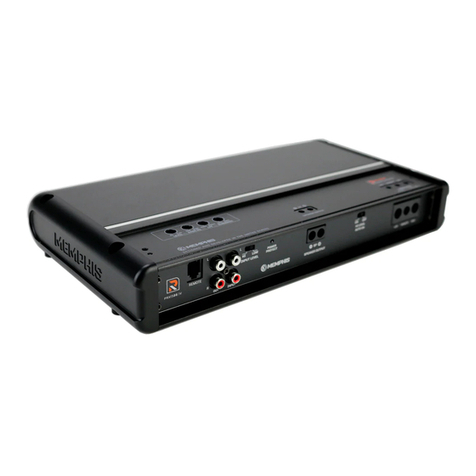
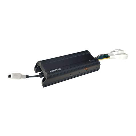
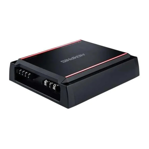
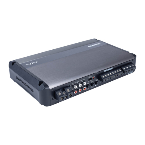
Memphis VIV Series User manual


MEMPHIS
VIV
SIXFIVE
SERIES
Ready
To
Turn
It
Up?
Read
This
First
Memphis
Audio
built
a
50
year
legacy
in
the
audio
industry
engineering
the
highest
quality
products
to
produce
the
best
possible
listening
experience
for
our
fans
and
loyal
supporters.
To
fully
appreciate
our
products
we
recommend
taking
the
time
to
read
and
follow
the
instructions
in
this
manual.
As
always,
we
recommend
all
installations
and
service
be
performed
by
an
authorized
Memphis
Audio
dealer
.
1
For
optimal
performance,
Memphis
recommends
using
only
Memphis
Connection
accessories.
Outfitting
your
system
with
properly
sized
Memphis
Connection
wire
and
accessories
will
dramatically
boost
your
listening
experience
and
increase
the
durability
of
your
Memphis
Audio
products.
VIV
Six
Five
Series
Amplifiers
feature
a
MOSFET
powersupply
with
a
24dB
per
octave
crossover
to
ensure
the
most
accurate
musical
reproduction
.
These
amplifiers
were
designed
to
be
acoustically
accurate
and
produce
powerful
crystal
clear
sound
to
your
audio
system.
Features
•
Brushed
anodized
aluminum
finish
•
1-Calar
selectable
color
changing
LED
Iago
{Re11ersible}
•
Super
-efficientfull
range
class
D
tapalagv
•
Bass
boast
up
ta
lBdB
•
Digital
Signal
Processing
{OSP}
with
211
dB
Crossa11er
Slopes
•
LED
Illuminated
end
caps
with
ground
lighting
.
•
M·Equalizatian
allows
Bass
Boast,
Freq
and
Qta
be
dialed
in
{MONO
Onlvl
•
Optional
wireless
bass
remote
ll/IV1300
.5
and
MONO
models
only}
Part
number
:
VIVREMV2

VIV
SIXFIVE
SERIES
Warranty
Memphis
Audio
Six
Five
Series
Amplifier
limited
Warranty
This
product
has
a2
year
warranty
from
the
date
of
purchase
for
defects
in
material
or
workmanship
.
This
warranty
will
be
extended
to
3
years
when
installed
by
a
Memphis
authorized
dealer
using
Memphis
Connection
products.
The
warranty
is
void
if
the
product
has
been
physically
damaged
by
improper
usage
or
abuse.
If
repairs
are
attempted
outside
of
a
Memphis
Audio
facility,
the
warranty
is
void.
This
warranty
is
limited
to
the
original
retail
purchaser
and
does
not
cover
any
expenses
incurred
in
the
removal
or
re-installation
of
the
product.
This
warranty
does
NOT
apply
to
product
exterior
and
cosmetics
.
Memphis
Audio
disclaims
any
liability
for
incidental
or
consequential
damages
caused
by
product
defects.
Memphis
Audio
liability
will
not
exceed
the
purchase
price
of
the
product
and
the
warranty
period
specified.
What
is
NOT
covered
under
warranty
•
Damage
due
to
improper
installation
•
Damage
caused
by
exposure
to
moisture,
excessive
heat,
chemical
cleaners
and/or
UV
radiation
•
Damage
through
negligence,
misuse,
accident
or
abuse.
(Repeated
returns
for
the
same
damage
may
be
abuse]
•
Product
damaged
in
accident
and/or
due
to
criminal
activity
•
Service
performed
by
anyone
other
than
Memphis
Audio
•
Subsequent
damage
to
other
components
•
Any
cost
or
expense
related
to
the
removal
or
re-installation
of
product
•
Products
with
tampered,
missing
,
altered
or
defaced
serial
numbers/labels
•
Freight
damage
•
The
cost
of
shipping
product
to
Memphis
Audio
•
Return
shipping
on
non-defective
items
•
Any
product
not
purchased
from
an
authorized
Memphis
Audio
dealer
Some
states
do
not
allow
the
exclusion
or
limitation
of
incidental
or
consequential
damages.
The
above
limitations
or
exclusions
may
not
apply
to
you.
This
warranty
gives
you
specific
rights,
you
may
have
other
rights
which
vary
from
state
to
state
.
If
warranty
service
is
required,
a
return
authorization
number
is
required
to
return
the
product
to
Memphis
Audio.
Warranty
shipments
to
Memphis
Audio
are
the
responsibility
of
the
purchaser
.
Pack
the
product
carefully
in
the
original
carton
if
possible
Memphis
Audio
will
not
be
responsible
for
damages
incurred
in
shipment
or
due
to
improper
packaging
materials
used
by
the
purchaser.
If
determined
to
be
within
warranty
your
product
will
be
repaired
or
replaced
at
the
discretion
of
Memphis
Audio.
Service/Returns
Please
consult
with
your
local
authorized
dealer
if
you
experience
issues
with
your
unit.
You
may
also
contact
Memphis
Audio
customer
service
at
800-1!89-2300
or
email
tech
support
directly
at
:
techsupport@memphiscaraudio
.
com
.
Do
not
attempt
to
return
your
amplifier
directly
to
us
without
first
calling
for
a
Return
Authorization
number
.
Units
received
without
an
accompanying
Return
Authorization
number
will
be
processed
more
slowly
.
Additionally
,
you
must
include
a
copy
of
your
purchase
receipt
from
an
authorized
dealer
for
consideration
of
in-warranty
service
,
otherwise
repair
charges
will
apply.
Units
received
without
a
receipt
will
be
held
for
up
to
30
days
allowing
us
time
to
contact
you
and
obtain
a
copy
of
the
receipt.
After
30
days
all
units
will
be
returned
to
you
unrepaired.

MEMPHIS
VIV
A U D I 0 S I N C E 1
'1
6 5 S I
XF
I
VE
SE
R I
ES
175Wxl
275Wx
I
375W
xi
SSOWxl
BSOWx
I
SBOWxl
SSOWxl
750Wx
I UOOWxl
1600Wx
I
750Wxl
UOOWxl
ISOOWxl
2200Wxl
3000Wxl
NIA
NIA N/A
NIA
N/A
N/A
NIA N/A
N/A
NIA
-'IOdB
at !kH
z,
-'IOdBatlkHz. ·
QOdB
at
!kHz.
-'IOdB
at
!kHz
,
-'IOdB
atlkHz.
·
36d8
at
20kHz
·
36d8
at
20kHz
·
36d8
at
20kHz
·36d8
at
20kHz
·
36d8
at
20kH
z
Measured
from
RCA
Output
Measured
from
RCA
Output
Measured
from
RCA
Output
Measured
from
RCA
Output
Measur
ed
from
RCA
Ou
tpu
t
!Vrms
Input
!Vrms
l
nput
!Vrms
Input
IVrms
I
nput
!V
rm
sI
npu
t
<1
%
<1%
<!% <!%
<1%
Y
es
Yes
Ye
s
Yes
Yes
Yes Yes Yes
Yes Yes
Ye
s
Yes
Yes Yes
Vas
20
•
200
Hz
20
•
200
Hz
20
·200
Hz
20
·
200
Hz
20
•
200
Hz
>
95d8
>95d8
>
95dB
>95d8
>95d8
200mV
·
SV
200mV·SV
200mV
·
SV
200mV·SV
200mV
·
SV
QOOmV
·
IOV
llOOmV
·
IOV
QOOmV·IOV
QOOmV
·
lOV
QOOmV
·
IOV
>
20K
>20K
>20K
>20K
>
20K
9V·
16V
9V
•
16V
9V·
16V
9V
·
16V
9V·l6V
PWR
•
RGB
PWR
•
RGB
PWR
•
RGB
PWR
•
RGB
PWR
•
RGB
PRT
•
Red
PRT
•
Red
PRT
•
Red
PRT
•
Red
PRT
•
Red
Yes
Yes Yes
Yes
Yes
Yes
Yes
Yes Yes
Yes
NIA NIA
N/A NIA NIA
NIA NIA
NIA
NIA
NIA
Ye
s
Yes
Y
es
Yes
Yes
LP
LP
LP LP
LP
50
•
200
Hz
50
·
200Hz
50
•
200
Hz
50
·
200
Hz
50
•
200
Hz
QBdB
IISdB
lllldB lllldB
QBdB
2Qd8
2Qd8 2Qd8
2Qd8
2Qd8
10·
BOHz
10
•
BOHz
10
•
BOHz
10
·
80Hz
10
•
BOHz
N/A
NIA
NIA
NIA N/A
NIA
NIA NIA N/A NIA
Ye
s
Yes Yes
Yes
Yes
Ye
s
Yes
Ye
s
Ye
s
Ye
s

VIV
SIXFIVE
SERIES
65WxQ
BOWxQ
70Wx6
75WxQ
75WxQ
•300Wxl
•300Wxl
lOOW
xq
150WxQ
125W,6
125W
xq•
500W
xl
125W
xq•
500W
xl
N/A
N/A
N/A
-lllllll
■
lilll-
IIOOWlllllll
■
lilll-
·
200Wx2
300Wx2
250Wx3
150Wx2
150Wx2
•
500W
x
112
Ohm)
•
500W
,
112
Ohm
)
>55db
>55db
>55dB
>55dB
>55dB
.qQdB
el
lkHL
-QOdB
atlkHL
.qodB
atlkHL
-QOdB
et
lkHL .qQdBatlkHL
·36dB
at
20k
Hz
·36dB
at
20kHz
·
36dB
at
20kHz
·
36dB
at
20kHz
·
36dB
at
20kHz
Measured
from
RCA
Output
Measured
from
RCA
Output
Measured
f
rom
Speaker
Output
Measured
from
Speaker
Output
Measured
from
Speaker
Outpu
t
lVrms
Input
lVrms
Input
lVrm
s
Input
!Vrms
Input
lVr
ms
Input
<1%
<1%
<1
% <1%
<1%
Yes
Yes
Vas
Yes
Yes
Yes
Yes
Yes
Yes
Yes
Yes
Ye
s
Vas
Yes Yes
Full
Range
Full
Range
10Hz
-
20kHz
10
Hz
·
20
kHz
10
Hz
·
20
kHz
10Hz
·
20kHz
10
Hz
·
20
k
Hz
Sub
Chann
el
Sub
Channel
20
Hz
·
200
Hz
20
Hz
·
200
Hz
>95dB
>95dB
>95dB
>95dB
>95dB
200mV
·
SV
200mV-SV
200mV-SV
200mV-SV
200mV
-
5V
QOOmV
-
lOV
QOOmV-
lOV
QOOmV
-
lOV
QOOmV-lOV
QOOmV-lOV
>
20K
>20K
>
20K
>20K
>20K
9V
-l
9V-l
-
16
9V-16V
9V
-
16V
PWR•RGB
PWR•RGB
PWR
•
RGB
PWR•RGB
PWR
•
RGB
PRT
•
Red
PRT
•
Red
PRT
•
Red
PRT
•
Red
PRT
•
Red
Yes
Yes
Yes
Yes Yes
Ye
s
Yes
Yes
Yes
Y
es
3
Yes
Yes
Yes
Yes
Yes
N/A
N/A
N/A
Yes
Yes
Yes
Yes
No
No
No
Front
•
Off/HP/LP
Front>Off/HP/lP
CHH!
oOff/HP/lP
Front-Off/HP/LP
Fron
t>
Off/HP/lP
Rea!"Off/HP/LP/BP
l!Hp(lff/HP/ll'IBI'
CH3-II
oOff/HM.PIBP
Rear-Off/HP/LP/BP Rear-Off/HP/LP/BP
CHH1
oOff/HP/lP
SUB
•
LP
SUB
• LP
Front
Front
CHH!
Front
Front
10-500
Hz
10
-
500
Hz 10-500Hz 10-500
Hz
1
0-
500
Hz
llOX
Switch)
llOX
Switch)
(!OX
Switch)
(!OX
Sw
i
tch)
(
!OX
Switch)
Rear
(2VRs)
R
ear12VRsl
CH3-II
Rearl2VRsl
Rear
l2VRsl
HP10
-
500Hz
HP
10
·
500
Hz
HP
•10-500Hz
HP
•
l0
-
500Hz
HP
•
l0-500Hz
LP
•
50
-
500Hz
LP
•50-500Hz
LP
•50-500Hz
LP
•
SO
-
SOOHz
LP•SO-SOO
Hz
l!OX
Switch)
l!OX
Switch}
(!OX
Switch)
(!OX
Switch)
llOX
Switch)
CHS-6
10
·5IXIMI
SUB
•
50
-
200
Hz
SUB
•
50
-
200
Hz
OOXW!:dtl
2QdB
2QdB
2QdB 2QdB 2QdB
N/A
N/A
N/A
SUB
CHANNEL:
2QdB
SUB
CHANNEL:
2QdB
N/A
N/A
NIA
SUB
CHANNEL:
SUB
CHANNEL
,
10
·
BOHz
10
·
BOHz
tHBdB tHBdB
CHl-i!
CH3-4
SUB
CHANNE
L:
SUB
CHANNEL:
0-lBdB
0-lBdB
0-lBdB
Q5Hz Q5Hz Q5Hz
SUB
CHANNEL:
Q5Hz
SUB
CHANNEL:
QSHz
N/A
NIA
NIA
Yes
Yes
*
VIV1300.5V2
6
VIVBHLE
Amplifiers
are
10
stable
on
the
5th
channel
only.
Only
operate
5th
channel
at
10
when
running
2
of
the
other
channels
at
20
or
higher.
Do
not
run
all
full
range
channels
at
20
with
5th
sub
channel
at
10,
doing
so
may
damage
the
amplifier.

MEMPHIS
VIV
A 0 N
SIXFIVE
SERIES
Installation
Information
Memphis
Audio
recommends
the
installation
of
our
products
to
be
performed
by
an
Authorized
dealer
.
Attempting
an
installation
project
on
your
own
or
through
an
unauthorized
source
may
result
in
damage
to
your
products
and
may
potentially
void
your
warranty.
Amplifiers
are
generally
mounted
in
the
hatch/trunk
area
of
your
car
or
SUV
or
behind
the
seat
of
most
pick
up
trucks
.
Select
a
location
that
provides
adequate
ventilation
.
Amplifier
should
be
secured
using
the
screws
provided
.
Warning
For
your
safety,
always
inspect
the
mounting
location
carefully
to
ensure
you
are
not
drilling
into
any
electrical
,
hydraulic,
fuel
or
fluid
lines
.
Always
check
your
speaker
load
with
a
multi-meter
before
connecting
the
amplifier
.
Connecting
any
speaker
load
lower
than
the
rated
impedance
of
the
amplifier
will
result
in
damage
to
the
amplifier.
Damage
of
this
nature
is
NDT
covered
under
warranty
.
Please
pay
close
attention
to
what
connections
are
made
to
the
amplifier
.
If
you
are
uncertain
or
uncomfortable
proceeding
with
your
installation
,
please
contact
your
local
authorized
Memphis
Audio
Dealer
Troubleshooting
When
troubleshooting
your
amp,
speaker
and
speaker
wires
should
be
tested
first
No
Output:
•
Confirm
all
wiring
is
firmly
connected
.
Both
+12V
and
REM
terminals
must
have
+12
Volts
present
and
GND
must
be
connected
to
chassis
'
ground
or
to
the
negative
battery
terminal.
•
Confirm
the
signal
source
is
connected
and
supplying
an
output
signal.
To
confirm
the
amp
is
working,
connect
an
RCA
patch
cord
to
the
line
inputs
of
the
amplifier
(do
not
connect
the
other
end
of
the
patch
cord).
Briefly
tap the
center
pin
of
each
disconnected
RCA
with
your
finger
.
This
should
produce
a
noise
(brief
static
or
hum)
in
the
speakers
.
•
If
the
amp
is
hot
,
check
the
speaker
impedance
or
load.
The
total
minimum
impedance
of
all
speakers
should
not
be
lower
than
the
rating
of
the
amp
.
Only
One
Channel
Works:
•
Confirm
the
speaker
terminal
strip
connections
are
firmly
connected
.
•
Check
"balance"
control
on
your
signal
source
.
•
If
using
RCA
low-level
inputs,
reverse
the
input
plugs
at
the
amplifier
.
If
the
channel
that
is
silent
reverses
position
,
the
problem
is
in
the
source
unit
or
connecting
cable.
Weak
Output
•
Check
input
sensitivity
control
adjustment.
Unwanted
Noise
•
Whine
that
increases
and
decreases
with
engine
speed
-
confirm
the
Amp
6
Source
unit
are
grounded
properly
.
•
Clicking
or
popping
noise
at
a
rate
that
follows
engine
speed
·
this
is
often
induced
by
the
vehicles
ignition
system
.
Confirm
that
the
vehicle
is
equipped
with
resistor
spark
plugs
and
wires.
The
ignition
system
may
need
service
.
•
Noise
can
be
caused
by
routing
speaker
input
wires
too
close
to
the
light
wires
and
other
accessory
wires
in
the
vehicle.
Re-route
wires
to
avoid
unwanted
interference.
·
If
above
steps
do
not
improve/reduce
noise
,
the
system
should
be
checked
by
a
professional
audio
installer
at
a
Memphis
Authorized
Dealer
.
Red
LED
is
Illuminated
•
Speaker
or
wire
is
shorted
•
Battery
voltage
too
low
•
Battery
voltage
too
high
•
Amplifier
has
overheated
due
to
improper
ventilation

VIV
SIXFIVE
SERIES
Power
Su
ly
Connections
fl>.
Install
the
fuse
at
the
battery
last!
&,
Use
conventional
stranded
copper
wire
for
all
connections.
Finish
the
ends
of
the
wi
res
at
the
amp
and
vehicle
with
proper
si
ze
terminals
.
Poorly
made
connections
and/or
inadequate
wire
size
will
generate
excessive
heat
and
may
lead
to
equipment
failure
.
12
Volt
•
Connection
make
the
12V+
connection
directly
at
the
positive
battery
post
using
the
proper
wire
size
and
fuse
listed
below,
The
fuse
should
be
installed
within
18"
of
the
battery.
This
fuse
is
vital
to
protecting
the
vehicle
from
damage
in
the
case
of
a
dead
short.
The
fuse
value
at
the
battery
should
be
at
least
equal
to
the
total
fuse
value
of
all
the
amplifiers
being
used
.
Ground
Connection:
Make
ground
connection
directly
to
the
chassis
of
the
vehicle
as
close
to
the
amp
as
possible
.
Make
sure
this
connection
is
made
with
the
same
wire
size
as
used
for
the
12
volt
connection.
Ensure
that
all
dirt
,
grease
,
paint
and
coatings
are
removed
prior
to
attaching
the
ground
wire
to
chassis
.
Remote
Turn-On
Remote
turn
on
should
be
connected
to
the
source
unit's
remote
turn
on
lead
.
Automatic
Turn-On
Selection:
The
Six
Five
series
offers
three
different
automatic
turn
-
on
modes
that
can
be
selected
on
the
end
panel
;
+12V
,
DC
Offset
,
and
Audio
.
Using
either
the
DC
Offset
or
Audio
mode
causes
the
REM
terminal
to
have
+12V
out
for
turning
on
additional
amplifiers
.
Remote
Turn-On
12V
method:
Set
the
switch
to
+12V
to
use
the
remote
turn
-
on
lead
from
your
source
unit.
Run
18
gauge
wire
from
the
Remote
Turn-On
lead
on
your
source
unit
to
the
terminal
labeled
REM
between
the
amplifier's
positive
and
negative
power
terminals
.
This
is
the
preferred
automatic
turn
-
on
method
.
Remote
Turn-On
DC
OFFSET
method:
If
Remote
Turn-On
is
not
an
option
,
the
next
best
setting
is
DC
Offset.
The
DC
Offset
mode
detects
a
6V
DC
offset
from
the
HI-Level
speaker
outputs
when
the
source
unit
has
been
turned
on
.
Remote
Turn-On
SIGNAL
SENSE
method:
The
Audio
setting
is
the
final
alternative
for
Automat
ic
turn-on
.
This
is
a
Signal
Sense
turn-on
method
that
detects
the
incoming
audio
signal
from
your
source
unit
and
automatically
turns
on
the
amp
.
This
turn
-
on
method
will
not
work
properly
if
the
input
gain
control
is
not
set
appropriately
.
Power
Connections
CHASSIS
GROUND
II
REMOTE
TURN
ON
FUSE
HOLDER
•II
12V
+
us
·
FRO
tAmRVJ
. I
11
•·- -
. . .
I'
......
1:
r
~r\l
1'
...
u
_,,
. " ~ u
i~ 0-
ooo
~-o
lee
eel
BATTERY
o ·
GO
o
;!~
L•
O
""
..
~~
~w
~
0,/nlVI'
'--~----'
VIV
0

MEMPHIS
VIV
AUDIO
SIN
E 1 9 6 5
SIXFIVE
SERIES
Signal
Input
Connections
The
VIV
amplifier
has
dual
input
sensitivity
differential
RCA
inputs
which
will
receive
either
high
or
low
level
signals
from
your
car
stereo
's
source
unit.
A
high-level
signal
can
be
run
from
the
source
unit's
speaker
outputs
to
the
stereo
RCA
input
on
the
end
panel
of
the
amplifier
using
RCA
cables
and
cutting
the
ends
to
expose
the
internal
wiring
.
This
wiring
can
then
be
connected
to
your
high
level
speaker
signal
and
plugged
into
the
amplifier,
be
sure
the
switch
on
the
amp
is
setto
"HI"
Alternatively
,
the
si
gnal
can
be
delivered
to
the
amplifier
us
i
ng
the
low-level
RCA
outputs
on
the
source
unit.
Set
the
input
level
switch
on
the
end
panel
of
the
amplifier
to
"LO"
.
Keep
the
audio
signal
cable
away
from
factory
wiring
harnesses
and
other
power
wiring
.
If
you
need
to
cross
this
wiring
,
cross
it
at
a
90
degree
angle
.
VIVIIOO.IIV2
//
VIV600
.
IIV2
VIV1300
.
5V2
//
VIVBELLE
@
I 0
_..,..__
OutTo
Additional
Amplifiers
0

IWUHWI
0 0
MBFI-
VIV3000.1V2
//
VIV2200.1V2
//
VIV1500.1V2
//
VIV1100.1V2
//
VIV750.1V2
N'UT
OUTPUT
0
Out
To
Additional
Amplifiers

MEMPHIS
A
D10
!>
NCE
19
VIV
SIXFIVE
SER
IE
S
Wiring
Multi-Channel
Amps
Speaker
have
a
positive
and
negative
marking
on
the
terminals
.
These
are
used
to
indicate
polar
i
ty
and
must
be
considered
when
wiring
speakers
or
subwoofers
to
an
amplifier
.
Amplifiers
also
have
positive
and
negative
markings
on
their
speaker
outpu
ts.
Use
these
mark
i
ng
to
ma
t
ch
polarities
to
ensure
the
speakers
are
in
phase
.
Failure
to
wire
speakers
or
woofers
in
phase
with
one
another
will
result
ina
loss
of
bass
.
All
Six
Five
Series
amplifiers
require
a
minimum
2
ohm
impedance
in
stereo
or
q
ohm
in
mono
(bridged)
mode
.
Always
check
your
speaker
load
with
a
multi-meter
before
hooking
them
up
to
the
amplifier
.
The
VIVII00
.
4¥2
amplifier
is
stable
to
2
ohms
stereo
or
4
ohms
bridged
mono.
The
VM300.5V2
//
VIVBELLE
amplifiers
are
stable
to
2
ohms
stereo
or
q
ohms
bridged
mono
(front
&
rear
channels)
and
stable
to
2
ohms
[sub
channel)
.
Any
Impedance
[load)
smaller
than
what
Is
recommended
will
damage
the
ampllflerl
Such
damage
is
not
covered
under
warranty
,
so
pay
strict
attention
to
what
connections
are
made
to
the
amplifier
.
VIVQOO.QV2
//
VIV600.'IV2
VIV1300.5V2
//
VIVBELLE
@
I
l\[
1-40
Speaker/Sub
qo
Speaker
/
Sub
•
•
qo
Speaker
/
Sub
2-LtO
Speaker
2-LtO
Speaker

VIV
SIXFIVE
SER
I
ES
Wiring
Single
Channel
Amps
VIV3DDD.1V2
//
VIV2200.1V2
//
VIV1500.1V2
//
VIV1100.1V2
//
VIV750.1V2
o:
-=-
;q;
p:
t 0
~
CJ
0
I L
,~"1
..
~
.....,,.
~
e A 0
N'VT
"'-""UT
---
-
✓,,
=
AeM
+t.!\/
110
Speaker/Sub
•
0 0
_
.....,..
_
•
110
Speaker/Sub
•
110
Speaker/Sub
WIRING
SUBWO
O
FERS
When
using
a
single
amplifier
to
power
one
subwoofer
,
the
positive
and
negative
terminal
of
the
subwoofers
voice
coil
is
connected
the
pos
i
tive
and
negative
terminal
of
the
Amplifier
.
Always
check
your
speaker
load
with
a
multi
-
meter
before
hooking
up
to
the
amplifier
.
The
VIV
Series
Mono
Amplifiers
amp
l
ifiers
are
1
ohm
stable.
Any
Impedance
(load)
sma
ll
er
than
1
ohm
will
d
amage
the
amplifier!
Such
damage
is
not
covered
under
warranty,
so
pay
strict
attention
to
wha
t
connections
are
made
to
the
amplifier
.

MEMPHIS
VIV
AUDIO
SIN
1 9 6 5
SIXFIVE
SERIES
-
POWER
-
Setup
And
Adjustment
MONO
Amplifiers
@ @
MEMPHIS
0
0 L
~
CJ
-CAnU
=-
0
F>RCr&CT
looool
0
A
c.NO
REM
➔
li!\/
._
_
N>./f
CU1"'UT
VIV
r-
EQUALIZATION
™--,
CENTER
BASS
GA
IN
SUB-SONIC
X-OVER
FREQ
Q
BOOST
Q
2S
•
Q?a
70
•
01~a
30
•
o:
60
• • • • • • Q Q
a
10 10
HZ
BO
SO
><2
200
20
HZ
BO
1 S 0
081B
Controls
are
located
under
top
plate
for
easy
access
+ + 0 -
SPEAKERS
vrv
\/IV2200.1V2
MEMPHIS
S I X F I
VE
S E R I E S
LED
COLOR
0
Input
level:
The
RCA
inputs
on
Sixfive
Series
amplifiers
are
capable
of
receiving
either
Hi
or
Low-level
signals
from
you
r
source
uni
t
If
the
only
output
available
from
your
source
unit
is
a
Hi-Level
signal
,
simply
press
in
the
Input
Level
switch
on
the
amplifier
.
Refer
to
the
wir
i
ng
section
of
this
manual
for
additional
instructions
.
Input
Gain
Control:
The
input
gain
control
is
not
a
volume
control.
It
matches
the
output
of
the
source
un
it
to
the
input
leve
lof
the
amplifie
r.
Turn
the
source
unit
up
to
about
3/q
volume
(if
the
source
unit
goes
to
30,
turn
it
to
25).
Next
,
slowly
turn
(c
lockwise)
the
ga
in
on
the
amplifier
up
until
you
can
hear
audible
distortion
,
then
turn
it
down
alittle.
Adjustable
Subsonic
Filter:
The
variable
subsonic
filter
will
provide
a
cut
-
off
point
for
lowe
r
frequenc
i
es
(10-BOHz)
that
could
potent
i
ally
damage
your
speakers
from
over
-
excursion
,
along
with
wasting
your
amplifie
r'
s
power
.
The
setting
for
this
control
should
be
set
relative
to
you
r
speaker
's
low-frequency
capability.
Crossover
Control:
The
variable
crossover
on
the
amplifier
is
always
active
,
and
allows
you
to
adjust
the
LO
-
PASS
crossover
frequency
from
qo
-
160Hz
.
The
setting
for
this
control
is
subjective
;
BO
Hz
is
a
good
place
to
start
.
Bass
Boost
Control:
The
variable
bass
boost
control
on
the
side
of
the
amplifier
is
designed
to
give
you
i
ncreased
output,
0-
1
8d8
,
at
the
selected
frequency
.A
higher
BANDWIDTH
[QI
sett
i
ng
will
result
in
a
sharper
cut
at
the
frequencies
above
and
below
the
sele
c
ted
center
f
req
uen
cy
.
The
setting
for
this
control
is
subjective.
If
you
turn
it
up
,
you
must
readjust
the
input
ga
in
control
to
avoid
cl
ipp
i
ng
the
ampli
fi
e
r.
Remote
Bass
Control
MVREM
Sold
Separately):
With
the
optional
VIVREM
remote
bass
level
control
,
you
have
the
ability
to
control
the
output
level
of
the
amplifier
remotely
.
To
surface-mount
the
VIVREM
remote
bass
level
control
,
simply
screw
the
remote
to
the
cho
sen
locat
i
on
.
The
VIVREM
is
set
to
pair
with
your
Sixfive
Series
amplifier
directly
out
of
the
box
and
will
immediatley
co
n
trol
you
r
amplifier
.
If
the
VIV
Re
mote
does
not
connect
to
your
amplifier
,
power
down
your
amplifier
and
powe
rit
back
on
,
the
r
emote
shou
ld
now
be
paired
.

@
I
VIV
I
CAIN
FRONT
==i
l
x-oveR
FRSQ
•
2&0
RANCE
90
~
~90
r-------i
.\.._,,/.
o•
io
OF'4/HP/\.P
,o
•
wa
Soo
1xnox
0
Setup
And
Adjustment
Continued
VIVBELLE
//
VIV1300
.
5V2
5-Channel
Amplifier
VIV
SIXFIVE
SERIES
VIVB00J5V2
MEMPHIS
S I X
FIVE
S E R I E S
~---su
e
----,
I
SUB
·SO
NIC
1.0--PA
SS
BASS
O
AIN
•SO
•
115
BOOST
l..liC
C:01..0~
Q z;Q
?O
~oi
so
Q
0
10
10H1
80
SOl-11200
001118
~
Controls
are
located
under
top
plate
for
easy
access
Input
Level:
The
RCA
inputs
on
SixFive
Series
amplifiers
are
capable
of
receiving
either
Hi
or
Low-level
signals
from
your
source
unit.
If
the
on
ly
output
available
from
your
sour
ce
unit
is
a
Hi
-
Level
signal
,
simply
press
in
the
Input
Level
switch
on
the
amplifier
.
Refer
to
the
wiring
section
of
this
manual
for
additional
instructions.
FR
Input
(Full
Range):
Depress
the
FR
switch
if
you
are
running
two
sets
of
inputs
(front
and
rear
for
example]
to
the
amplifier
.
leave
the
FR
switch
OFF
if
you
want
to
drive
all
channels
from
a
single
stereo
input.
Sub
Input:
If
there
is
no
dedicated
output
on
your
source
unit
for
a
subwoofer,
use
the
SUB
INPUT
switch
to
set
your
subwoofer
input
to
either
SUB
INPUT
or
REAR
.
Input
Gain
Control:
The
input
gain
control
is
not
a
volume
control.
It
matches
the
output
of
the
source
unit
to
the
input
level
of
the
amplifier.
Turn
the
source
unit
up
to
about
3/q
volume
(if
the
source
unit
goes
to
30
,
turn
it
to
25).
Next,
slowly
turn
[clockwise]
the
gain
on
the
amplifier
up
unti
l
you
can
hear
audible
distortion
,
then
turn
it
down
alittle.
Bass
Boost
Control:
The
variab
le
bass
boost
control
on
the
amplifier
is
designed
to
give
you
increased
output
,
0-lBdB
,
at
q5
Hz
.
The
setting
for
this
control
is
subjective.
If
you
turn
it
up,
you
must
readjust
the
input
gain
control
to
avoid
clipping
the
amplifier
.
Crossover
Switches
with
Frequency
Multiplier:
Use
the
XOVER
switches
on
the
amplifier
to
set
the
internal
crossovers
for
FRONT
6
REAR
to
OFF
,
HI-PASS,
LO-PASS,
or
BAND
-
PASS
!REAR
only]
.
When
the
switch
is
set
to
OFF
,a
full
bandwidth
signal
will
be
amp
l
ified
.
Set
the
switch
to
HP
if
you
want
the
amplifier's
internal
crossover
to
serve
as
a
high-pass
filter.
Set
the
switch
to
LP
if
you
want
the
amplifier's
i
nterna
l
crossover
to
serve
as
a
low-pass
filter
.
Set
the
sw
i
tch
to
BP
when
a
specific
frequency
range
is
required.
Never
change
the
crossover
switches
with
the
audio
system
on!
Set
the
lX/lOX
frequency
multiplier
switch
to
the
setting
that
is
appropriate
for
your
application
.A
setting
of
lOX
will
set
the
range
of
the
FRONT
crossover
to
100-5,000Hz
,
and
the
LO-PASS
crossover
of
REAR
to
500
-5,
000Hz
.
FR
input
(full
Range):
Depressing
button
selects
q
Channel
,
raised
button
selects
2
channel
inputs.
If
2CH
or
qcH
is
selected
on
the
VIV900
.5,
the
subwoofer
channel
will
be
provided
.

MEMPHIS
AuOIO
SN
0
VIV
6
Setup
And
Adjustment
Continued
VIV750.6V2
&·Channel
Amplifier
0
Controls
are
located
under
top
plate
for
easy
access
VIV
SIXFIVE
SERIES
0
MEMPHIS
S I X
FIVE
S E R I E S
Leo
C O
LOR
0
Input
Level:
The
RCA
inputs
on
Sixfive
Series
amplifiers
are
capable
of
receiving
either
Hi
or
low-level
signals
from
your
source
unit.
If
the
only
output
available
from
your
source
unit
is
a
Hi·level
signal
,
simply
press
in
the
Input
level
switch
on
the
ampl
i
fier
.
Refer
to
the
wir
i
ng
section
of
this
manual
for
additional
instructions
.
Input
Gain
Control:
The
Input
gain
control
is
not
a
volume
control.
It
matches
the
output
of
the
source
un
it
to
the
input
level
of
the
amplifier.
Turn
the
source
unit
up
to
about
3/4
volume
(if
the
source
unit
goes
to
30,
turn
it
to
25)
.
Next
,
slowly
turn
(clockwise)
the
gain
on
the
amplifier
up
until
you
can
hear
audible
distortion,
then
turn
it
down
alittle.
Crossover
Control
with
Frequency
Multiplier
Switch:
The
variable
crossover
on
the
side
of
the
amplifier
allows
you
to
set
the
cr
ossover
to
OFF
,
HI·PASS
,
LO·PASS
or
BAND
·
PASS
at
frequencies
from
lOHz-5
,
000Hz
.
The
setting
for
this
control
is
subjective
.
Bass
Boost
Control:
The
variable
bass
boost
control
on
the
SixFive
Series
amplifier
is
designed
to
give
you
increased
output
,0-
lBdB
,
at
45Hz.
The
setting
for
this
control
is
subjective.
If
you
turn
it
up
,
you
must
readjust
the
input
gain
control
to
avoid
clipping
the
amplifier
.
Band
pass
crossover:
With
the
crossover
switch
in
the
"
BP
"
setting
,
you
can
use
both
the
low
pass
and
high
pass
adjustments
to
create
your
custom
band
pass
filter.
Use
the
HI·PASS
adjustment
to
change
the
frequency
point
of
the
low-end
slope
.
Use
the
LO-PASS
adjustment
to
change
the
frequency
point
of
the
high
end
slope
.
This
feature
allows
you
to
custom
tune
the
sound
of
your
mid-range
speaker
.
You
can
match
the
size
and
frequency
response
of
your
mid-r
a
nge
speaker
to
the
amp
allowing
you
to
get
the
most
out
of
your
speakers.
Bandpau
fil~r
HI·PASS
adjustment
LO
·
PASS
adjustment
• --

MEMPHIS
A U O C , C E 1 9
VIV
SIXFIVE
SER
I
ES
Setup
And
Adjustment
Conti
n
ued
mqoo.qv2 //
VIV&Oo.q
q-channet
Amplifier
VIV
CiAIN
. .
0
10
FRONT---~
r-
X-F~~~R
~
I •
260
RANCE
90
Ll30
. .
..
OFF/HP/LP
10
HZ
500
lX
I
lOX
BASS
BOOST
. .
0
CBlB
Controls
are
located
under
top
plate
for
easy
access
MEMPHIS
S I X F I
VE
S E R I E S
REAR-----~
.----
X-OVER
---,
HI-PASS
LO-PASS
LO-PASS
~AIN
e l 6 0 •
230
RANGE
90
Ll30
. ,. . .
_
100
350
~
·
10
OFF/HP/LP/BP
l~Hz
;o
o
s~HZ~oo
lX
I10,C
BASS
BOOST
. .
OCB
1B
LEO
COLOR
Input
level:
The
RCA
inputs
on
Sixfive
Series
Amplifiers
are
capable
of
receiving
either
Hi
or
Low-level
signals
from
your
source
unit.
If
the
only
output
available
from
your
source
unit
is
a
Hi-Level
signal
,
simply
press
in
the
FR
(Full
Range)
switch
on
the
ampl
i
fier
.
Either
input
method
will
provide
a
low-level
output
signal
at
the
RCA
output,
which
effectively
passes
the
audio
signal
to
another
amplifier
or
component.
Refer
to
the
wiring
section
of
this
manual
for
additional
instructions
.
Input
Gain
Control:
The
input
gain
control
is
not
a
volume
control.
It
matches
the
output
of
the
source
unit
to
the
input
level
of
the
amplifie
r.
Turn
the
source
unit
up
to
about
3/q
volume
(if
the
source
unit
goes
to
30,
turn
it
to
25).
Next
,
slowly
turn
(clockwise)
the
gain
on
the
amplifier
up
until
you
can
hear
audible
distortion.
then
turn
it
down
alittle.
Crossover
Switches
with
Frequency
Multiplier:
Use
the
XOVER
switches
on
the
amplif
i
er
to
set
the
internal
crossovers
of
REAR
6
FRONT
to
OFF,
HI
-
PASS
,
LO
-
PASS
,
or
BANO
·
PASS
(FRONT
only)
.
When
the
switch
is
set
to
OFF,
a
full
bandwidth
signal
will
be
amplified
.
Set
the
switch
to
HP
if
you
want
the
amplifier's
internal
crossover
to
serve
as
a
high
-
pass
filter.
Set
the
switch
to
LP
if
you
want
the
amplifier's
internal
crossover
to
serve
as
a
low-pass
filter.
Set
the
switch
to
BP
when
a
specific
frequency
range
is
required.
Never
change
the
crossover
switches
with
the
audio
system
on!
Set
the
lX/lOX
frequency
multiplier
switch
to
the
setting
that
is
appropriate
fur
your
application
.A
setting
of
lOX
will
set
the
range
of
the
REAR
crossover
to
100-5
,
000Hz
,
and
the
LO-PASS
crossover
of
FRONT
to
500-5
,
000Hz
.
Bass
Boost
Control:
The
variable
bass
boost
control
on
the
SixFive
Series
amplifier
is
designed
to
give
you
increased
output
,0-
18dB
,
at
q5Hz
.
The
setting
for
this
control
is
subjective
.
If
you
turn
it
up
,
you
must
readjust
the
input
gain
control
to
avoid
clipp
i
ng
the
amplifier
.
Input
Mode
Switch:
Depressing
button
selects
q-channel
,
raised
button
selects
2
channel
inputs
.


w
■
(_)
z
lf)
0
0
::::>
<(
i....io::,·01
□
n'tft:::1'tf::JSIHdi..1!3i..ll"ffiffiffi
This manual suits for next models
10
Table of contents
Other Memphis Amplifier manuals

Memphis
Memphis SRX150.2 User manual

Memphis
Memphis MXA480.4M User manual

Memphis
Memphis POWER REFERENCE PRX1500.1V User manual
Memphis
Memphis VIV SIXFIVE Series User manual

Memphis
Memphis MXA600.6 User manual

Memphis
Memphis PRX300.4 User manual

Memphis
Memphis VIV Sixfive Series User manual

Memphis
Memphis MXA300.2 User manual

Memphis
Memphis MXA300.1 User manual
Memphis
Memphis SRX250.1 User manual