MEN MH70S User manual
User Manual
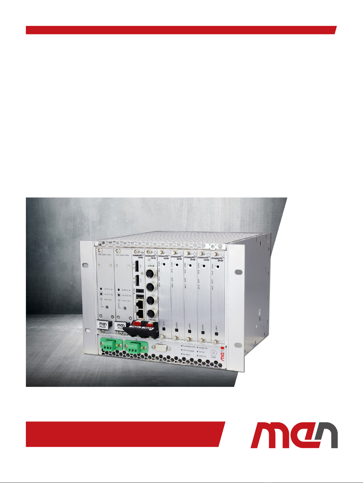
MH70S
Rugged Data Storage & NAS Computer with Intel Core i3/i5/i7
Modular Embedded System for Industrial Automation & Railway Transport
2019-10-2420MH70S00 E3

20MH70S00 E3
2019-10-24 Page 2
Contents
Contents
Contents. . . . . . . . . . . . . . . . . . . . . . . . . . . . . . . . . . . . . . . . . . . . . . . . . . . . . . . . . . 2
About this Document . . . . . . . . . . . . . . . . . . . . . . . . . . . . . . . . . . . . . . . . . . . . . . 4
Product Safety . . . . . . . . . . . . . . . . . . . . . . . . . . . . . . . . . . . . . . . . . . . . . . . . . . . . 6
Product Compliance . . . . . . . . . . . . . . . . . . . . . . . . . . . . . . . . . . . . . . . . . . . . . . . 7
Disclaimer . . . . . . . . . . . . . . . . . . . . . . . . . . . . . . . . . . . . . . . . . . . . . . . . . . . . . . . . 8
Contacts . . . . . . . . . . . . . . . . . . . . . . . . . . . . . . . . . . . . . . . . . . . . . . . . . . . . . . . . . . 9
1 Product Overview . . . . . . . . . . . . . . . . . . . . . . . . . . . . . . . . . . . . . . . . . . . . . . 10
1.1 Product Description . . . . . . . . . . . . . . . . . . . . . . . . . . . . . . . . . . . . . . . . . . . . . . .10
1.2 Product Architecture . . . . . . . . . . . . . . . . . . . . . . . . . . . . . . . . . . . . . . . . . . . . . .11
1.2.1 Possible Applications and Configurations . . . . . . . . . . . . . . . . . . . .11
1.3 Technical Data . . . . . . . . . . . . . . . . . . . . . . . . . . . . . . . . . . . . . . . . . . . . . . . . . . . .13
1.4 Cooling Concept . . . . . . . . . . . . . . . . . . . . . . . . . . . . . . . . . . . . . . . . . . . . . . . . . .16
1.5 Product Identification. . . . . . . . . . . . . . . . . . . . . . . . . . . . . . . . . . . . . . . . . . . . . .17
2 Getting Started . . . . . . . . . . . . . . . . . . . . . . . . . . . . . . . . . . . . . . . . . . . . . . . . 18
2.1 Unpacking the MH70S . . . . . . . . . . . . . . . . . . . . . . . . . . . . . . . . . . . . . . . . . . . . .18
2.2 Scope of Delivery . . . . . . . . . . . . . . . . . . . . . . . . . . . . . . . . . . . . . . . . . . . . . . . . .18
2.3 Configuring the Hardware. . . . . . . . . . . . . . . . . . . . . . . . . . . . . . . . . . . . . . . . . . 19
2.3.1 Installing an HDD/SSD . . . . . . . . . . . . . . . . . . . . . . . . . . . . . . . . . . . . .19
2.4 Mounting the MH70S . . . . . . . . . . . . . . . . . . . . . . . . . . . . . . . . . . . . . . . . . . . . . .22
2.4.1 Safety Instructions for Mounting . . . . . . . . . . . . . . . . . . . . . . . . . . . . 22
2.4.2 Wall-Mounting the MH70S . . . . . . . . . . . . . . . . . . . . . . . . . . . . . . . . . 23
2.4.3 Mounting the MH70S in a 19" Rack . . . . . . . . . . . . . . . . . . . . . . . . . .25
2.5 Connecting and Starting . . . . . . . . . . . . . . . . . . . . . . . . . . . . . . . . . . . . . . . . . . .29
2.5.1 Safety Instructions for Connection. . . . . . . . . . . . . . . . . . . . . . . . . .29
2.5.2 Connecting an Earthing Cable . . . . . . . . . . . . . . . . . . . . . . . . . . . . . .29
2.5.3 Connecting Peripherals. . . . . . . . . . . . . . . . . . . . . . . . . . . . . . . . . . . .30
2.5.4 Connecting the Power Supply . . . . . . . . . . . . . . . . . . . . . . . . . . . . . .30
2.6 Starting Up the System . . . . . . . . . . . . . . . . . . . . . . . . . . . . . . . . . . . . . . . . . . . .31
2.7 Installing Operating System Software . . . . . . . . . . . . . . . . . . . . . . . . . . . . . . . .31
2.8 Installing Driver Software . . . . . . . . . . . . . . . . . . . . . . . . . . . . . . . . . . . . . . . . . . 31
3 Functional Description. . . . . . . . . . . . . . . . . . . . . . . . . . . . . . . . . . . . . . . . . . 32
3.1 Power Supply. . . . . . . . . . . . . . . . . . . . . . . . . . . . . . . . . . . . . . . . . . . . . . . . . . . . .32
3.1.1 Power Button . . . . . . . . . . . . . . . . . . . . . . . . . . . . . . . . . . . . . . . . . . . .32
3.2 System Management . . . . . . . . . . . . . . . . . . . . . . . . . . . . . . . . . . . . . . . . . . . . . .33
3.2.1 Control Panel LEDs. . . . . . . . . . . . . . . . . . . . . . . . . . . . . . . . . . . . . . . .33
3.3 Slots of the MH70S . . . . . . . . . . . . . . . . . . . . . . . . . . . . . . . . . . . . . . . . . . . . . . . .35
3.4 CPU . . . . . . . . . . . . . . . . . . . . . . . . . . . . . . . . . . . . . . . . . . . . . . . . . . . . . . . . . . . . .37
3.4.1 Processor Core . . . . . . . . . . . . . . . . . . . . . . . . . . . . . . . . . . . . . . . . . . .37
3.5 Trusted Platform Module (TPM) . . . . . . . . . . . . . . . . . . . . . . . . . . . . . . . . . . . . .37
3.6 Mass Storage . . . . . . . . . . . . . . . . . . . . . . . . . . . . . . . . . . . . . . . . . . . . . . . . . . . . .38
3.6.1 SATA . . . . . . . . . . . . . . . . . . . . . . . . . . . . . . . . . . . . . . . . . . . . . . . . . . . . 38
3.6.2 mSATA . . . . . . . . . . . . . . . . . . . . . . . . . . . . . . . . . . . . . . . . . . . . . . . . . .38

20MH70S00 E3
2019-10-24 Page 3
Contents
3.7 Ethernet . . . . . . . . . . . . . . . . . . . . . . . . . . . . . . . . . . . . . . . . . . . . . . . . . . . . . . . . .38
3.7.1 Ethernet Interface Functionality . . . . . . . . . . . . . . . . . . . . . . . . . . . .38
3.7.2 Ethernet Switch Functionality. . . . . . . . . . . . . . . . . . . . . . . . . . . . . . .38
3.8 Wireless Functionality . . . . . . . . . . . . . . . . . . . . . . . . . . . . . . . . . . . . . . . . . . . . . 39
3.9 Third-Party Plug-In Boards . . . . . . . . . . . . . . . . . . . . . . . . . . . . . . . . . . . . . . . . . 39
4 Maintenance . . . . . . . . . . . . . . . . . . . . . . . . . . . . . . . . . . . . . . . . . . . . . . . . . . 40
4.1 Cleaning the System . . . . . . . . . . . . . . . . . . . . . . . . . . . . . . . . . . . . . . . . . . . . . . .40
4.2 Lithium Battery . . . . . . . . . . . . . . . . . . . . . . . . . . . . . . . . . . . . . . . . . . . . . . . . . . .40
4.3 Fuse Protection . . . . . . . . . . . . . . . . . . . . . . . . . . . . . . . . . . . . . . . . . . . . . . . . . . . 40
4.4 Installing or Removing Plug-In Boards. . . . . . . . . . . . . . . . . . . . . . . . . . . . . . . .42
4.4.1 Installing a Plug-In Board . . . . . . . . . . . . . . . . . . . . . . . . . . . . . . . . . .42
4.4.2 Removing a Plug-In Board . . . . . . . . . . . . . . . . . . . . . . . . . . . . . . . . .42
Figures
Figure 1. MH70S configuration example: maximum configuration . . . . . . . . . . . . . . . .12
Figure 2. Bottom and top of system not covered: airflow from bottom to top . . . . . . 16
Figure 3. Product label (BTO model) . . . . . . . . . . . . . . . . . . . . . . . . . . . . . . . . . . . . . . . . . . 17
Figure 4. Power configuration and coding labeling (example) . . . . . . . . . . . . . . . . . . . .30
Figure 5. Slots of the MH70S. . . . . . . . . . . . . . . . . . . . . . . . . . . . . . . . . . . . . . . . . . . . . . . . .35
Tables
Table 1. Connector types – power supply (3-pin COMBICON) . . . . . . . . . . . . . . . . . . . .32
Table 2. Pin assignment – power supply (3-pin COMBICON) . . . . . . . . . . . . . . . . . . . . . 32
Table 3. Signal mnemonics – power supply . . . . . . . . . . . . . . . . . . . . . . . . . . . . . . . . . . .32
Table 4. Power button: system behavior. . . . . . . . . . . . . . . . . . . . . . . . . . . . . . . . . . . . . .32
Table 5. Control panel LEDs . . . . . . . . . . . . . . . . . . . . . . . . . . . . . . . . . . . . . . . . . . . . . . . .33
Table 6. Slots of the MH70S (function and configuration) . . . . . . . . . . . . . . . . . . . . . . . 36
Table 7. Processor core options . . . . . . . . . . . . . . . . . . . . . . . . . . . . . . . . . . . . . . . . . . . . .37

20MH70S00 E3
2019-10-24 Page 4
About this Document
About this Document
This document is intended only for system developers and integrators.
It describes the design, functions and connection of the product. The manual does not
include detailed information on individual components (data sheets etc.).
It provides an overview of the system and describes possible functions. For a detailed
description of the functionality of the individual boards please refer to the boards’ user
manuals.
History
MH70S product page with up-to-date information and downloads:
www.men.de/products/mh70s/
Issue Comments Date
E1 First issue 2015-12-11
E2 Updated according to current BTO excel file, new
structure
2017-09-15
E3 Added G227 (G212 not supported anymore)
Updated G22 (not supported anymore)
Updated Chapter Cooling Concept
Updated Chapter Safety Instructions for Mounting
Updated Chapter Slots of the MH70S
2019-10-24
20MH70S00 E3
2019-10-24 Page 5
About this Document
Conventions
Indicates important information or warnings concerning situations which
could result in personal injury, or damage or destruction of the
component.
Indicates important information concerning electrostatic discharge which
could result in damage or destruction of the component.
Indicates important information or warnings concerning proper
functionality of the product described in this document.
The globe icon indicates a hyperlink that links directly to the Internet.
When no globe icon is present, the hyperlink links to specific information
within this document.
Italics Folder, file and function names are printed in italics.
Comment Comments embedded into coding examples are shown in green text.
IRQ#
/IRQ
Signal names followed by a hashtag "#" or preceded by a forward slash "/"
indicate that this signal is either active low or that it becomes active at a
falling edge.
In/Out Signal directions in signal mnemonics tables generally refer to the
corresponding board or component, "in" meaning "to the board or
component", "out" meaning "from the board or component".
0xFF Hexadecimal numbers are preceded by "0x".
0b1111 Binary numbers are preceded by "0b".

20MH70S00 E3
2019-10-24 Page 6
Product Safety
Product Safety
Read the user manual carefully before using the product. Keep the user manual for later
reference.
Conditions for Use, Field of Application
The product is designed to function correctly in the market, application area and
environmental conditions specified in the applicable standards which are listed in the
Technical Data.
Use cases in environments exceeding the specifications in the applicable standards and
the Technical Data have to be agreed upon between MEN and the customer.
Electrostatic Discharge (ESD)
Qualified Personnel
The product/system described in this documentation may be operated only by
personnel qualified for the specific task in accordance with the relevant documentation,
in particular its warning notices and safety instructions. Qualified personnel are those
who, based on their training and experience, are capable of identifying risks and
avoiding potential hazards when working with these products/systems.
Computer boards and components contain electrostatic sensitive devices.
Electrostatic discharge (ESD) can damage components. To protect the PCB
and other components against damage from static electricity, follow some
precautions whenever you work on your computer.
Power down and unplug your computer system when working on the
inside.
Hold components by the edges and try not to touch the IC chips, leads,
or circuitry.
Use a grounded wrist strap before handling computer components.
Place components on a grounded antistatic pad or on the bag that came
with the component whenever the components are separated from the
system.
Only store the product in its original ESD-protected packaging. Retain
the original packaging in case you need to return the product to MEN for
repair.

20MH70S00 E3
2019-10-24 Page 7
Product Compliance
Product Compliance
MEN products are tested according to the standards given in the Technical Data and thus
enable you to achieve certification of the product according to the standards applicable
in your field of application.
If the product delivered was certified by MEN and is modified by the customer, e.g., by
installing an additional hardware component, the certification achieved by MEN
becomes invalid and may have to be repeated for the new product configuration.
RoHS
MEN is committed to develop and produce environmentally compatible products
according to the Restriction of Hazardous Substances (RoHS) Directive 2011/65/EU
(formerly 2002/95/EC) of the European Union.
Since July 1, 2006 all MEN standard products comply with RoHS legislation.
REACH
MEN is a manufacturer of electronic products and thus a so-called "downstream user" in
terms of REACH. The products MEN supplies are solely non-chemical goods. Moreover
and under normal and reasonably foreseeable circumstances of application, the goods
supplied shall not release any substance.
Beyond that, according to REACH – Art.33, MEN will inform the customer immediately
should a substance contained in an MEN product (with a content of > 0.1%) be classified
alarming by the European Chemicals Agency (ECHA).
WEEE Application
Nevertheless, MEN is registered as a manufacturer in Germany. The registration number
can be provided on request.
The WEEE directive does not apply to fixed industrial plants and tools. The
compliance is the responsibility of the company which puts the product
on the market, as defined in the directive; components and sub-
assemblies are not subject to product compliance.
Since MEN does not deliver ready-made products to end users, the WEEE
directive is not applicable for MEN. Users are nevertheless recommended
to properly recycle all electronic boards which have passed their life cycle.

20MH70S00 E3
2019-10-24 Page 8
Disclaimer
Disclaimer
Changes
MEN Mikro Elektronik GmbH ("MEN") reserves the right to make changes without further
notice to any products herein.
Liability
MEN makes no warranty, representation or guarantee of any kind regarding the
suitability of its products for any particular purpose, nor does MEN assume any liability
arising out of the application or use of any product or circuit, and specifically disclaims
any and all liability, including, without limitation, consequential or incidental damages.
TO THE EXTENT APPLICABLE, SPECIFICALLY EXCLUDED ARE ANY IMPLIED WARRANTIES
ARISING BY OPERATION OF LAW, CUSTOM OR USAGE, INCLUDING WITHOUT LIMITATION,
THE IMPLIED WARRANTIES OF MERCHANTABILITY AND FITNESS FOR A PARTICULAR
PURPOSE OR USE. In no event shall MEN be liable for more than the contract price for
the products in question. If buyer does not notify MEN in writing within the foregoing
warranty period, MEN shall have no liability or obligation to buyer hereunder.
Should the customer purchase or use MEN products for any unintended or
unauthorized application, the customer shall indemnify and hold MEN and its officers,
employees, subsidiaries, affiliates, and distributors harmless against all claims, costs,
damages, and expenses, and reasonable attorney fees arising out of, directly or
indirectly, any claim or personal injury or death associated with such unintended or
unauthorized use, even if such claim alleges that MEN was negligent regarding the
design or manufacture of the part. In no case is MEN liable for the correct function of the
technical installation where MEN products are a part of.
The publication is provided on the terms and understanding that:
1. MEN is not responsible for the results of any actions taken on the basis of
information in the publication, nor for any error in or omission from the publication; and
2. MEN is not engaged in rendering technical or other advice or services.
MEN expressly disclaims all and any liability and responsibility to any person, whether a
reader of the publication or not, in respect of anything, and of the consequences of
anything, done or omitted to be done by any such person in reliance, whether wholly or
partially, on the whole or any part of the contents of the publication.

20MH70S00 E3
2019-10-24 Page 9
Contacts
Contacts
Copyright © 2019 MEN Mikro Elektronik GmbH. All rights reserved.
Germany
MEN Mikro Elektronik GmbH
Neuwieder Straße 1-7
90411 Nuremberg
Phone +49-911-99 33 5-0
France
MEN Mikro Elektronik SAS
18, rue René Cassin
ZA de la Châtelaine
74240 Gaillard
Phone +33-450-955-312
www.men.de
www.men-france.fr
USA
MEN Micro Inc.
860 Penllyn Blue Bell Pike
Blue Bell, PA 19422
Phone 215-542-9575
China
MEN Mikro Elektronik (Shanghai) Co., Ltd.
Room 1212, #993 West Nanjing Road
Shanghai 200041
Phone +86-21-5058-0963
www.menmicro.com
www.men-china.cn

Product Overview
20MH70S00 E3
2019-10-24 Page 10
1 Product Overview
1.1 Product Description
Modular, Built-to-Order Configuration
The MH70S is a modular turn-key storage PC which meets the requirements of storage
intensive applications such as digital video recorders, content servers or NAS. It is
designed for use in trains, trams or industrial environments.
The system consists of a modular 40 HP CompactPCI Serial system which can be wall or
rack-mounted. The system can be cooled by using an additional fan tray at the bottom of
the system. Cooling is independent of the mounting position.
The PC offers a multitude of configuration possibilities which are built to order resulting
in a fast time-to-market.
Storage, Ethernet Switch and Wireless Functionality
Thanks to its up to five HDD/SSD carriers (2 HDDs each), the MH70S forms a high
performance and high capacity storage system. Up to eight PoE PSE ports supplying
eight devices with a maximum of 100 Watts in total can be implemented. For robust and
safe operation, the HDD carriers can be configured in RAID 0, 1 or 5 while the carriers
themselves have their own internal RAID 0, 1 and JBOD hardware configuration
possibility.
The system offers up to 2 Gigabit Ethernet interfaces at the front of the CPU board. PCI
Express Mini cards for wireless functions such as WLAN and UMTS can also be provided.
High-Performance Processor and System Control
The system is based on a high-performance Intel Core i7 processor supporting Intel AMT
functionality. Data security can be assured using a TPM module. A system management
controller complements the self-control and self-monitoring capabilities. It manages life-
time information about, e.g., the fans, power supplies and can be used for manual
shutdown.
Redundant Power Supply
The pre-configured system offers two PSU slots to ensure reliability and redundancy.
Normal operation is guaranteed if at least one external voltage is present. AC or DC
power supplies can be implemented. Each power supply has its own power source. This
allows the system to be fed from independent power distribution networks assuring fail-
over functionality and power-cut bridging.

Product Overview
20MH70S00 E3
2019-10-24 Page 11
1.2 Product Architecture
The MH70S is a build-to-order system. It consists of the 40 HP basic system including
backplane and mounting rails and provides:
2 slots for PSU
1 CompactPCI Serial slot for the CPU board
6 CompactPCI Serial peripheral slots for Ethernet switch and mass storage function-
ality
The boards and accessories listed in the Technical Data can be implemented in the
system.
The following shows some typical configuration examples of the MH70S. As the product
concept is very flexible, other configurations are also possible.
1.2.1 Possible Applications and Configurations
1.2.1.1 Application Example: NAS
The MH70S can be used as a media server, a video recorder or as an NAS system.
The system can be used with the open source OpenMediaVault operating system.
The operating system OpenMediaVault is based on the Linux distribution Debian and
offers a complete and user-friendly NAS and RAID management as well as monitoring
via SNMP, diagnosis interfaces and remote functions like Samba/NFS, FTP or iSCSI.
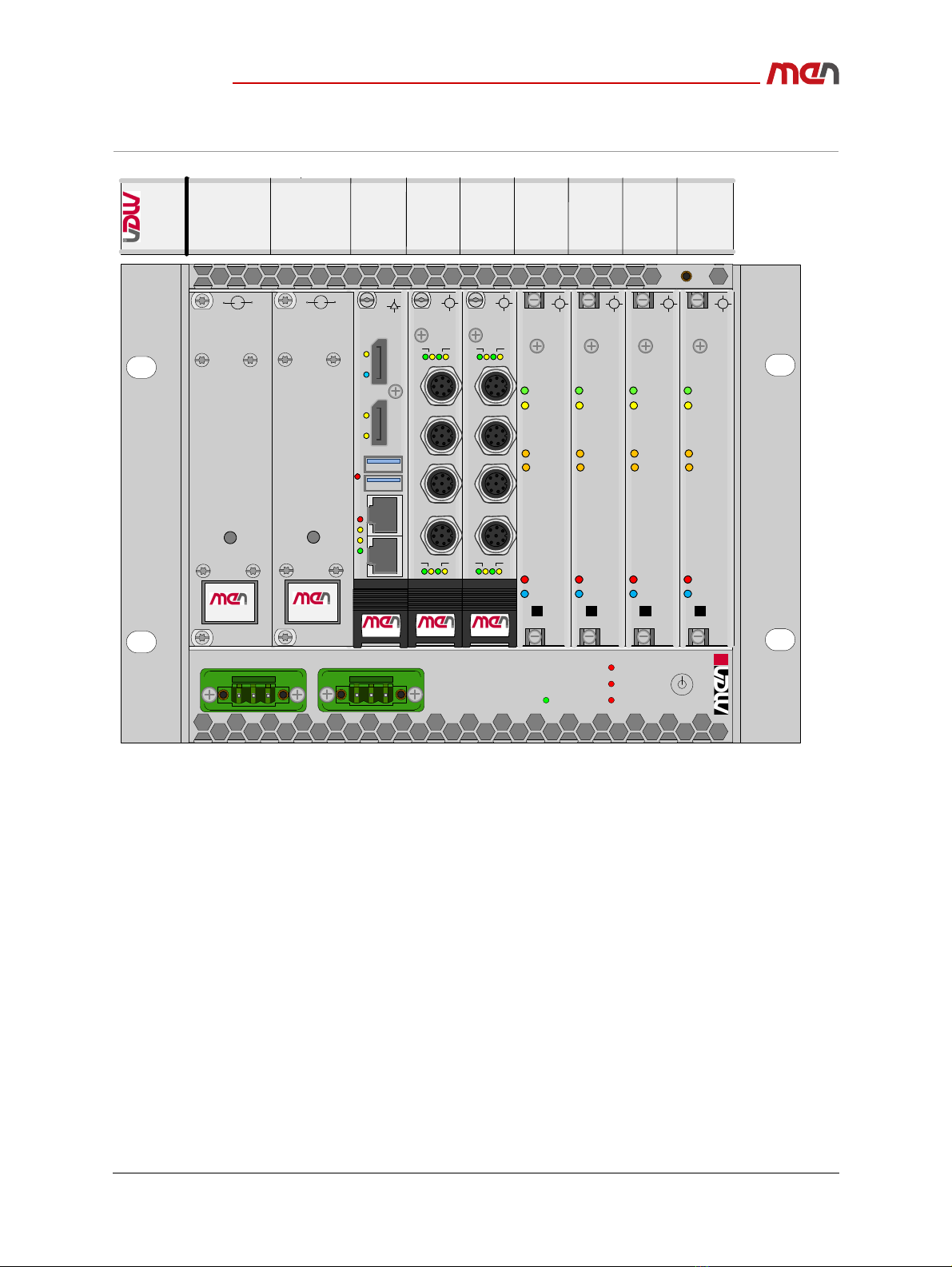
1.2.1.2 Configuration Example: Maximum Configuration
The configuration example illustrates a configuration including:
Eight PoE PSE ports supplying eight devices with a maximum of 100 Watts in total
Four dual HDD carriers with 2 HDDs/SSDs each. Configured as one drive a capacity
of about 16 TB (with 2 TB 2.5” HDDs installed) can be achieved.
Chapter 3.3 Slots of the MH70S on page 35 lists all components that can be
implemented in the system.
Choose the functionality you need using the BTO configurator and the BTO
Configuration Guide.
Contact MEN for more information.
Product Overview
20MH70S00 E3
2019-10-24 Page 12
Figure 1. MH70S configuration example: maximum configuration
Card 2
System Status
Voltage Fail
Fan Fail
Temp Fail
X1
Power
STATUS
DC/DC 120W
-+
PU20
23456
Slot
PSU CPU I/O I/O I/O I/O I/O
1
I/O
STATUS
DC/DC 120W
-+
PU20
®
CompactPCI
Serial
EJECT
HP
AC2AC1
LOCPWR
®
CompactPCI
Serial
EJECT
HP
AC2AC1
LOCPWR
®
CompactPCI
Serial
EJECT
HP
AC2AC1
LOCPWR
®
CompactPCI
Serial
EJECT
HP
AC2AC1
LOCPWR
X2
G304
Serial
®
CompactPCI
12
L A L A
43
L A L A
X1
X2
X3
X4
G304
Serial
®
CompactPCI
12
L A L A
43
L A L A
X1
X2
X3
X4
G23
DP2
3 4
DP1
1 2
RST
®
CompactPCI
Serial
Product Overview
20MH70S00 E3
2019-10-24 Page 13
1.3 Technical Data
CPU Board
CPCI Serial 3U Board
Configurable: yes
Possible Configurations:
-Intel Celeron 2002E 1.5 GHz, 4 GB DDR3 DRAM with ECC, front: 2 DisplayPort,
2 USB, 2 Gb Ethernet (RJ45), -40°C to +85°C, conformal coating
-Intel Core i7-4700EQ 2.4 GHz, 16 GB DDR3 DRAM with ECC, front: 2 DisplayPort,
2 USB, 2 Gb Ethernet (RJ45), 0°C to +60°C
Mass Storage
-SSD mSATA, 8 GB, -40°C to +85°C or
-SSD mSATA 3.x, 64 GB, MLC, -40°C to +85°C
Supervision and Control
Dedicated shelf controller monitors power, CPU status, temperature; controls fan;
provides status LEDs and power button
Power Supply
PSU 3U
Configurable: yes
Possible Configurations:
-120 W, 3U 6 HP PSU, wide range input 24 to 110 V DC, 24 V DC nom.,
output 12 V / 5 V / 3.3 V DC, -40°C to +85°C, conformal coating
-120 W, 3U 6 HP PSU, wide range input 100 to 240 V AC,
output 12 V / 5 V / 3.3 V DC, -40°C to +85°C, conformal coating
Two separate power inlet connectors
Normal operation if at least one external voltage is present
G23 Embedded Single Board Computer with Intel Core i3 / i5 / i7:
www.men.de/products/g23/
AF2 Shelf Controller for CompactPCI Systems:
www.men.de/products/af2/
PU20 Wide-Range Railway Power Supply Unit, 24 to 110 VDC, 120 W
:
www.men.de/products/pu20/
PU21 Wide-Range Railway Power Supply Unit, 100 to 240 VAC, 120 W
:
www.men.de/products/pu21/
Product Overview
20MH70S00 E3
2019-10-24 Page 14
Wireless Functionality via PCI Express Mini Cards
CPCI Serial 3U Board
Configurable: yes
Possible in CompactPCI Serial peripheral slot: 1, 2
3 PCI Express Mini Card slots (USB and PCIe), -40°C to +85°C
-More information on G227 PCI Express Mini Card carrier
Ethernet Interface Functionality
CPCI Serial 3U Board
Configurable: yes
Possible in CompactPCI Serial peripheral slot: 1
Possible Configurations
-4 1000Base-T Ethernet interfaces, 4 RJ45 connectors at front, 0°C to +60°C
-4 1000Base-T Ethernet interfaces, 4 M12 connectors at front, -40°C to +85°C,
conformal coating
Ethernet Switch Functionality
CPCI Serial 3U Board
Configurable: yes
Possible in CompactPCI Serial peripheral slot: 1, 2
Possible Configurations
-5-port unmanaged Gigabit Ethernet Switch (4 front ports, 1 rear port) with PoE+
(60 W max), USB PoE management, RJ45, -40°C to +70 (+85)°C
-4-port unmanaged Gigabit Ethernet Switch with PoE, M12, -40°C to +70 (+85)°C,
conformal coating
G227 PCI Express Mini Card carrier:
www.men.de/products/g227/
G211 Quad Gigabit Ethernet Interface Board:
www.men.de/products/g211/
G304 Smart Managed 4-Port Industrial Ethernet Switch with PoE+:
www.men.de/products/g304/

Product Overview
20MH70S00 E3
2019-10-24 Page 15
Mass Storage
CPCI Serial 3U Board
Configurable: yes
Possible in CompactPCI Serial peripheral slot: 2, 3, 4, 5, 6
Possible Configurations
-Two 2.5" SATA HDD/SSD shuttle, hot swap, RAID 0, 1 JBOD support, -40°C to
+85°C, conformal coating
Mechanical Specifications
Dimensions:
-(W) 210 mm, (D) 225 mm, (H) 175 mm max. without brackets
-4U, 40 HP
Mounting Possibilities
-Wall-mount
-Rack-mount in 19" cabinet
-Two systems side-by-side to build a single 19" chassis
Environmental Specifications
Temperature range (operation): EN 50155 class TX depending on configuration
-0°C to +50°C for high performance passenger information / video distribution
systems with PoE and fans
Temperature range (storage): -40°C to +85°C
Cooling concept
-Air-cooled, forced convection with fan tray at system bottom
Relative humidity (operation): according to EN 60068-2-30, non-condensing
Relative humidity (storage): according to EN 60068-2-30
Altitude: -300 m to +3000 m
Shock: according to EN 61373 category 1 class B
Vibration: according to EN 61373 category 1 class B
International Protection Rating (IEC 60529): IP20
Product Compliance: Radio Equipment
EMC basic compliance: The product is prepared to comply with the Radio
Equipment Directive 2014/53/EU (RED). Standards compliance depends on the
assembled radio (wireless) device.
Safety
Electrical Safety
-EN 60950-1: Class I equipment
Flammability (PCBs)
-UL 94 V-0
G503 Dual SATA HDD/SSD Shuttle & RAID Controller:
www.men.de/products/g503/
Product Overview
20MH70S00 E3
2019-10-24 Page 16
EMC Conformity
EN 55022 class B (radiated and conducted emissions)
EN 55024 (immunity)
Software Support
Linux
OpenMediaVault for Network Attached Storage
Windows Embedded Standard 7 (on request)
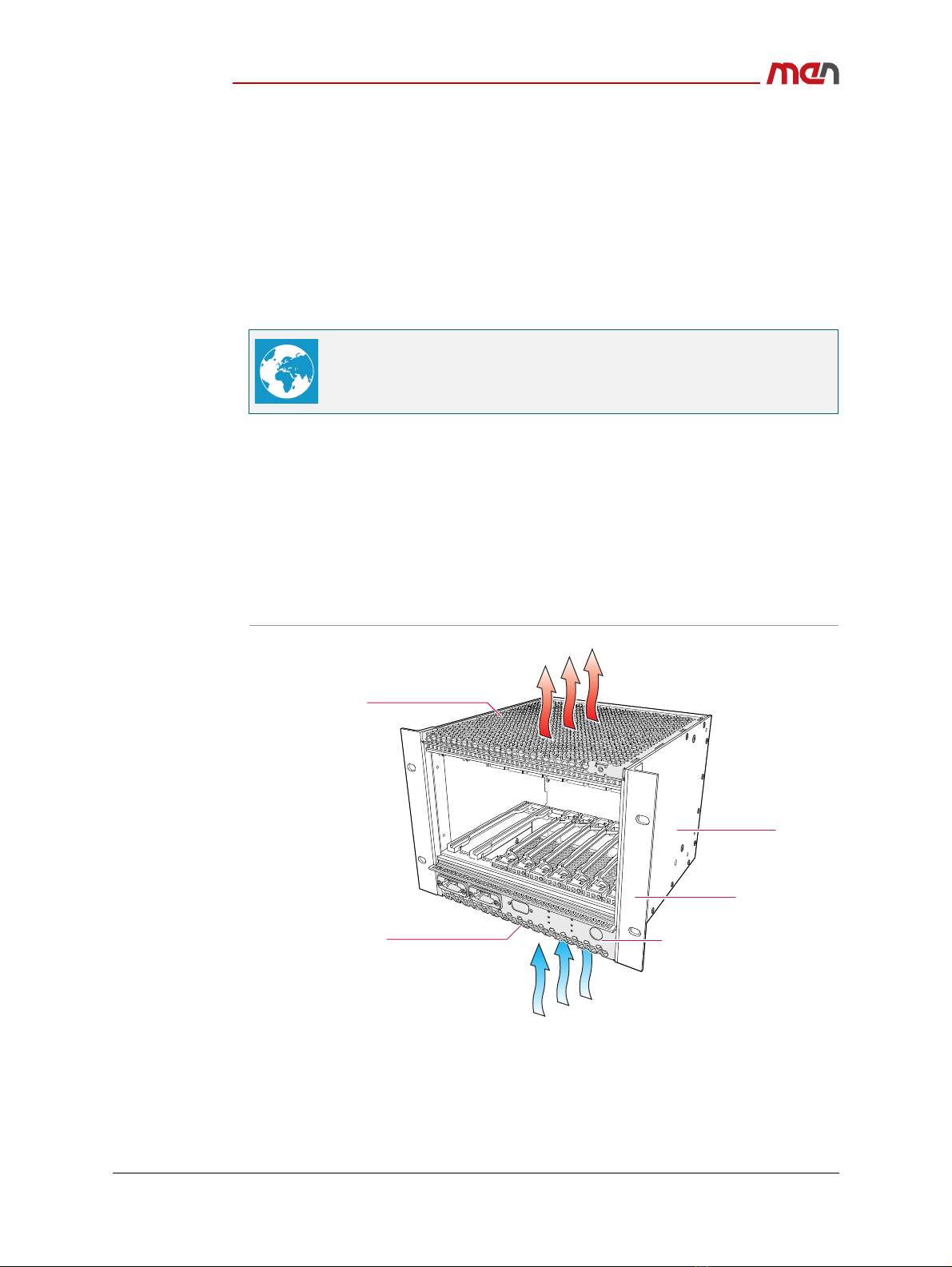
1.4 Cooling Concept
Cooling of the MH70S depends on its total power consumption:
Natural convection for fanless operation
- Not possible with MH70S
Forced convection using two fans in a fan tray at the bottom of the housing
- Required with some of the CPUs available
Figure 2. Bottom and top of system not covered: airflow from bottom to top
See the MEN website for supported operating system versions, available
software and more details on supported functions:
www.men.de/products/mh70s/#downl
Perforated boom panel
Mounng bracket
Front panel with connector slots
Side panel
Perforated top panel
Product Overview
20MH70S00 E3
2019-10-24 Page 17
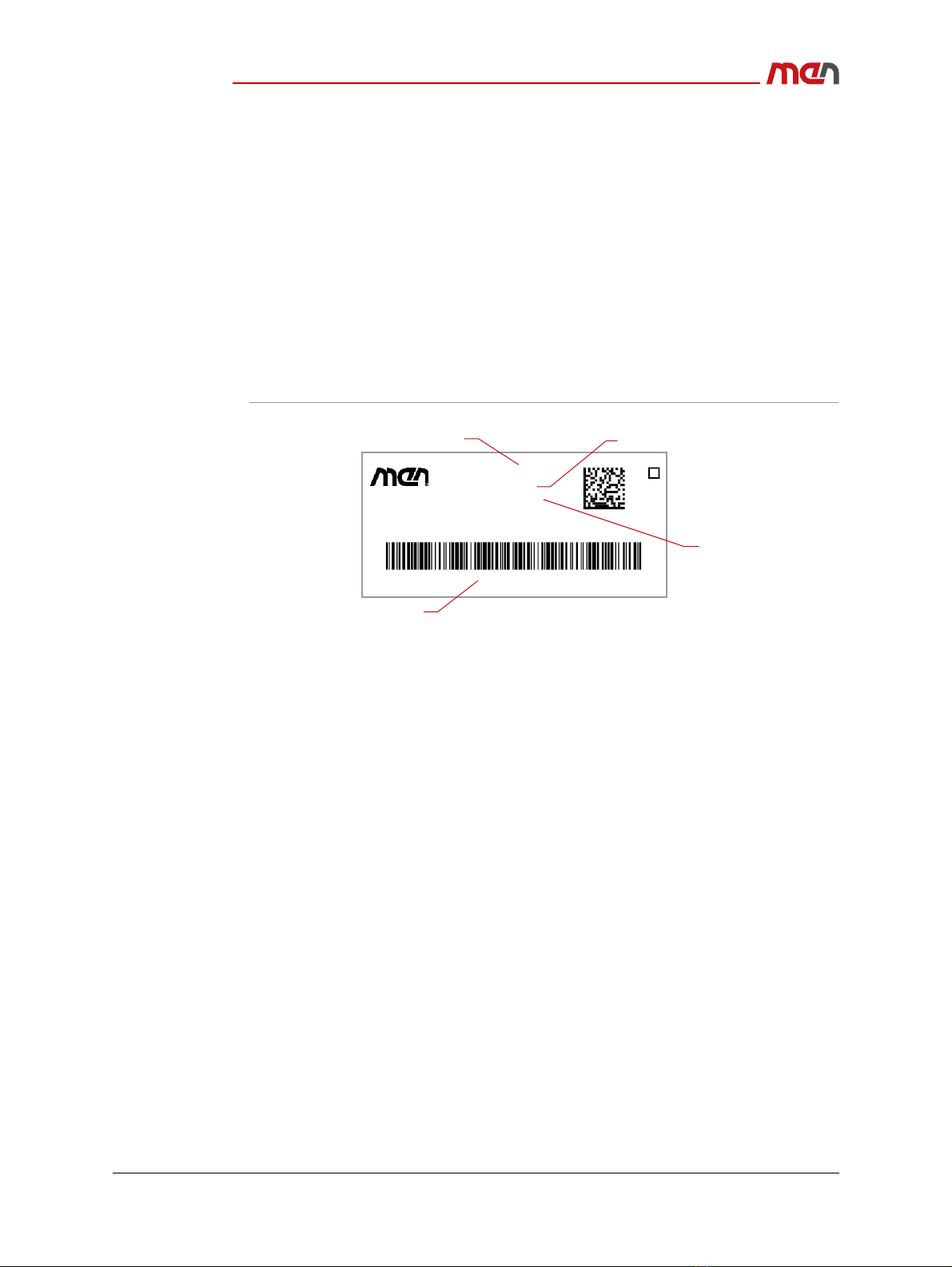
1.5 Product Identification
MEN user documentation may describe several different models and/or design revisions
of the MH70S. You can find information on the article number, the design revision and
the serial number on a label affixed to the chassis.
Article number: Indicates the product family and model. To be complete it must
have 9 characters.
Revision number: Indicates the design revision of the product.
Serial number: Unique identification assigned during production.
Ordering key: Unique ordering number of a built-to-order (BTO) configuration.
If you need support, you should communicate these numbers to MEN.
Figure 3. Product label (BTO model)
Serial No.: 000001
Made in Germany
Ordering key:
Rev. No.:
Article No.:
00.00.00
19MH70SB0
1223GH54442J22353HH3221
Revisionnumber
Orderingkey
Basicarticlenumber Serialnumber

Getting Started
20MH70S00 E3
2019-10-24 Page 18
2 Getting Started
2.1 Unpacking the MH70S
After unpacking, check whether there are any transport or other damages on the
system. If one of the following situations arises, have the equipment checked by service
personnel:
The power cable or plug is damaged.
Liquid has penetrated into the equipment.
The equipment has been exposed to moisture.
The equipment has been dropped and damaged.
The equipment has obvious signs of breakage.
2.2 Scope of Delivery
The delivery includes the following accessories:
Two coded mating connectors for the power supply (Phoenix)
Four M4x12 countersink head screws coated with securing material for mounting
Electric Shock and Fire Hazard Caused by Damaged Device
Damaged equipment may be under dangerous voltage and can cause fire.
Damaged equipment has unpredictable behavior and characteristics.
Prevent damaged equipment from being installed and put into
operation.
Mark the damaged equipment and keep it under lock and key.
Send the equipment to repair immediately.
Damage from Condensation
When the equipment has been subjected to low temperatures or extreme
temperature variations, condensation can form on or inside the system.
Humidity causes short circuits in electric circuits and damages the system.
To avoid damages, do the following:
Store the equipment in a dry environment.
Ensure that the equipment has the same temperature as the
environment before starting it up.
Do not subject the equipment to the direct radiation of a heating device.
Wait until the equipment has dried completely or wait 12 hours before
switching on the equipment.
See Chapter 2.4.2 Wall-Mounting the MH70S on page 23 and Chapter 2.4.3
Mounting the MH70S in a 19" Rack on page 25.

Getting Started
20MH70S00 E3
2019-10-24 Page 19
2.3 Configuring the Hardware
Check your hardware requirements before mounting the MH70S. Modifications are
difficult or impossible to do when the MH70S is mounted.
2.3.1 Installing an HDD/SSD
Perform the following steps before installing the HDDs/SSDs:
»Power down your system.
»Remove the carrier board from the system.
»If there are already HDDs/SSDs installed:
Installing the first HDD/SSD:
»Place the first HDD/SSD in the slot close to the front panel on the carrier board and
align it with the guide rails.
»Align the SATA connector on the HDD/SSD with the SATA connector on the carrier
board.
»Firmly plug the HDD/SSD into the SATA connector on the carrier board.
MEN offers suitable accessory articles for MH70S.
See the MEN website for ordering information:
www.men.de/products/mh70s/#ord
Getting Started
20MH70S00 E3
2019-10-24 Page 20
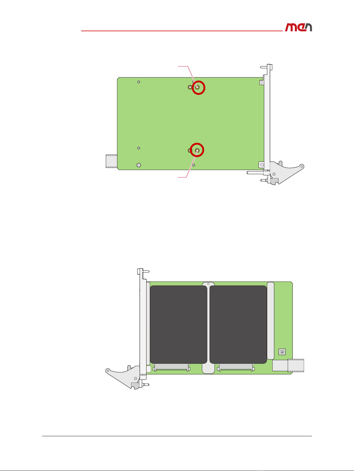
»Fasten the HDD/SSD to the board from the bottom side with two M3x8 TX8 socket
head screws (position highlighted in red in the following drawing).
»Secure the HDD/SSD additionally by fixing it to the front panel with a M3x6 TX8
screw.
»Apply thread locker to ensure the screws are not loosened by vibrations.
Installing the second HDD/SSD:
»Place the second HDD/SSD in the slot close to the rear connector on the carrier
board and align it with the guide rails.
»Align the SATA connector on the HDD/SSD with the SATA connector on the carrier
board.
»Firmly plug the HDD/SSD into the SATA connector on the carrier board.
Screw hole
Screw hole
Table of contents


