MES 16S1P Mounting instructions

Lithium-Iron Phosphate Battery
User Operation Manual
Product Name:PS5120E / PS5120ES
Model:16S1P
Information Version: 2.1
MES Technology Company.,Ltd

1/ 30
Contents
1. Introduction ..................................................................................................................................... 2
2. Function Characteristics ................................................................................................................ 3
3. Parameters ...................................................................................................................................... 4
4. Environmental Characteristics ...................................................................................................... 5
5. Electrical Characteristics ............................................................................................................... 6
5.1 System schematic diagram................................................................................................ 6
5.2 Port Definition ....................................................................................................................... 6
5.3 Definition of communication port pin............................................................................... 8
5.4 DIP (SWITCH) for PS5120E/PS5120ES ................................................................................ 10
5.5 Lights.................................................................................................................................... 12
6. Battery Pack .................................................................................................................................. 13
6.1 Size and Picture for PS5120E ............................................................................................. 13
6.2 Size and Picture for PS5120ES ........................................................................................... 13
7 Assembly Parts List......................................................................................................................... 14
7.1 List for PS5120E.................................................................................................................... 14
7.2 List for PS5120ES .................................................................................................................. 15
8. System operation steps................................................................................................................ 17
9 Installation ...................................................................................................................................... 18
9.1 Package items for battery module package of PS5120E: ........................................... 18
9.2 Package items for battery module package of PS5120ES: ......................................... 22
10. Safety Regulations ...................................................................................................................... 26
10.1 Safe handling of lithium batteries Guide ...................................................................... 26
10.2 Warning............................................................................................................................. 27
10.3 Against risk ........................................................................................................................ 28
10.4 Dangerous mode............................................................................................................. 28
MES Technology Company.,Ltd

2/ 30
1. Introduction
PS5120E/ PS5120ES lithium iron phosphate battery is one of new energy storage
products developed and produced by manufacture, it can be used to support
reliable power for various types of equipment and systems. PS5120E/ PS5120ES is
especially suitable for application scene of high power, limited installation space,
and restricted load-bearing and long cycle life.
PS5120E/ PS5120ES has built-in BMS battery management system, which can
manage and monitor cells information including voltage, current and temperature.
What’s more, BMS can balance cells charging and discharging to extend cycle
life. Multiple batteries can connected in parallel to expand capacity and power in
parallel for larger capacity and longer power supporting duration requirements.
MES Technology Company.,Ltd

3/ 30
2. Function Characteristics
◆The whole module is non-toxic, non-polluting and environmentally friendly.
◆Cathode material is made from LiFePO4 with safety performance and long cycle
life.
◆Provide over charge, over discharge, over current, short circuit and other
protection to ensure the safe and stable operation of the system.
◆Status indicator: displays SOC and fault status information.
◆It can detect the temperature of battery cell, environment and power MOS, and
can make alarm and protection actions when charging or discharging at high or
low temperature. There are 6 channels of NTC, 4 channels of battery cell
temperature detection, 1 channel of ambient temperature detection, and 1
channel of power MOS temperature detection.
◆RS485 communication, CAN communication function.
◆The charge balance strategy can be flexibly set (turn-on voltage, balance
voltage), which can effectively improve the battery's use time and cycle life.
◆It has the ability to perform various battery management parameters such as cell
overvoltage and undervoltage, pack total voltage over and undervoltage,
charging overcurrent, discharging overcurrent, cell high and low temperature,
environmental high and low temperature, balancing strategy, battery series
connection number, battery capacity, etc. It can be set to turn on and off the
discharge MOS, charge MOS, current-limiting function switch, buzzer alarm switch,
forced sleep switch and online upgrade function of the system software.
◆Flexible configuration, multiple battery modules can be in parallel for expanding
capacity and power.
◆Adopted self-cooling mode rapidly reduced system entire noise.
MES Technology Company.,Ltd

4/ 30
3. Parameters
Parameter Summary
Item
Specification
PS5120E
PS5120ES
Remark
Nominal voltage
51.2V
51.2V
Operating voltage range
44.8~57.6V
44.8~57.6V
Standard charging voltage
56.5V
56.5V
Nominal capacity
100Ah
100Ah
Standard Charge Current
33A
33A
Typical value:
0.33C
Max Charge Current
80A
80A
Standard Discharge Current
33A
33A
Typical value:
0.33C
Max Discharge Current
100A
100A
Weight
45kg
49kg
Net weight
Battery Dimensions
460*440*133 mm
505*450*205 mm
Cycle life
6000 cycle
@25℃0.5C
90% DOD
In parallel
Up to 30 PCS
Up to 30 PCS
MES Technology Company.,Ltd

5/ 30
4. Environmental Characteristics
Item
Specification
Remark
Operating
Temperature
Charge
0℃~45℃
Discharge
-20℃~60℃
Recommend
23ºC ±2ºC
Storage
Temperature
1 month
-10℃~60℃
High temperature
storage is not
recommended
3 months
-10℃~45℃
12 months
-10℃~25℃
Recommend
21℃~25℃
Relative humidity
5% to 95% Relative
Humidity
MES Technology Company.,Ltd

6/ 30
5. Electrical Characteristics
5.1 System schematic diagram
5.2 Port Definition
Front view:For PS5120E
MES Technology Company.,Ltd
P+
P-
ON/OFF
RESET
DIP
Dry contact
Power
Status
Alarm
Battery Capacity LED
RS485/CAN
RS232
3
RS485 Parallel Port
PE-GND
ClientNO.1
P+
P- COM
ClientNO.3
P+
P- COM
ClientNO.2
P+
P- COM
Host
P+
P- COM
COM0
…
PCS
…

7/ 30
Front view:For PS5120ES
Back view:For PS5120ES
Battery Capacity LED
ON/OFF
PE-GND
P+
P-
Status indicator
Reset
DIP
Dry contact
RS 485/CAN
RS 232
RS 485 Parallel Port
MES Technology Company.,Ltd

8/ 30
L/R view:For PS5120ES
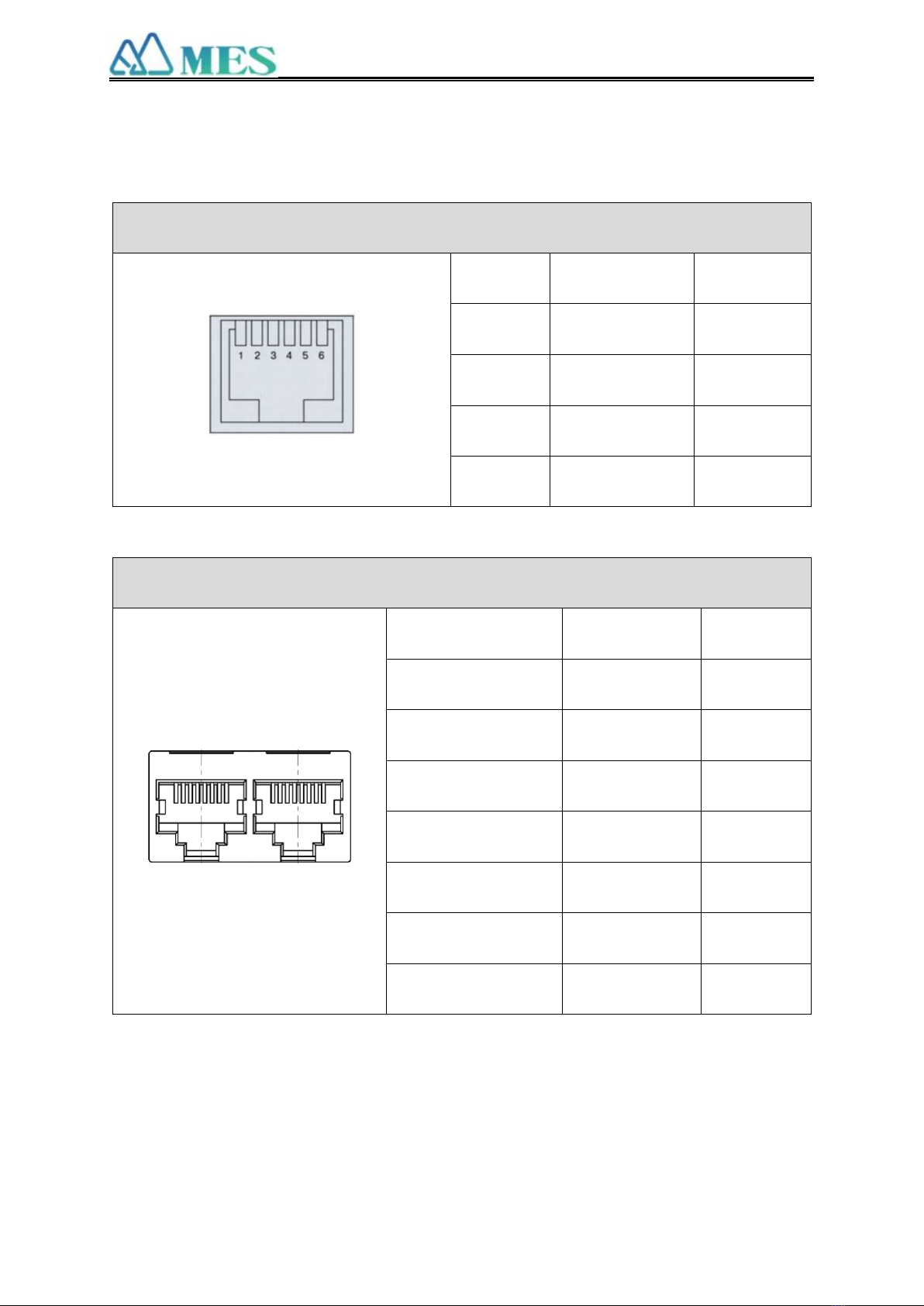
5.3 Definition of communication port pin
The communication port is mainly divided into three parts. See the following
table for specific definitions
PCS communication(RS485)
Pin
Definition
Remarks
1,8
RS485_B
2,7
RS485_A
3,6
RS485_GND
4,5
NC
PCS communication(CAN)
Pin
Definition
Remarks
4
CAN_H
5
CAN_L
7
CAN_GND
1,2,3,6,8
NC
Handle
RS485
CAN
MES Technology Company.,Ltd
9/ 30
PC communication (232)
Pin
Definition
Remarks
1,2,6
NC
3
TXD
4
RXD
5
GND
Parallel communication (RS485)
Pin
Definition
Remarks
1,8
RS485_B
2,7
RS485_A
3,6
RS485_GND
4,5,12,13
NC
9,16
RS485_B
10,15
RS485_A
11,14
RS485_GND
16
1
MES Technology Company.,Ltd

10 / 30
5.4 DIP (SWITCH) for PS5120E/PS5120ES
DIP (ADD) Switch: 5 ADD switches, to definite different address code for each
battery module when multiple modules are cascaded, up to 6 addresses.
ADD
Dial code switch position
1#
2#
3#
4#
5#
1
ON
OFF
OFF
OFF
OFF
2
OFF
ON
OFF
OFF
OFF
3
ON
ON
OFF
OFF
OFF
4
OFF
OFF
ON
OFF
OFF
5
ON
OFF
ON
OFF
OFF
6
OFF
ON
ON
OFF
OFF
7
ON
ON
ON
OFF
OFF
8
OFF
OFF
OFF
ON
OFF
9
ON
OFF
OFF
ON
OFF
10
OFF
ON
OFF
ON
OFF
11
ON
ON
OFF
ON
OFF
12
OFF
OFF
ON
ON
OFF
13
ON
OFF
ON
ON
OFF
14
OFF
ON
ON
ON
OFF
15
ON
ON
ON
ON
OFF
16
OFF
OFF
OFF
OFF
ON
17
ON
OFF
OFF
OFF
ON
MES Technology Company.,Ltd

11 / 30
18
OFF
ON
OFF
OFF
ON
19
ON
ON
OFF
OFF
ON
20
OFF
OFF
ON
OFF
ON
21
ON
OFF
ON
OFF
ON
22
OFF
ON
ON
OFF
ON
23
ON
ON
ON
OFF
ON
24
OFF
OFF
OFF
ON
ON
25
ON
OFF
OFF
ON
ON
26
OFF
ON
OFF
ON
ON
27
ON
ON
OFF
ON
ON
28
OFF
OFF
ON
ON
ON
29
ON
OFF
ON
ON
ON
30
OFF
ON
ON
ON
ON
NOTE: The address corresponding to ADD1 in the table is the host, and all other
addresses are the clients.
MES Technology Company.,Ltd

12 / 30
5.5 Lights
LED lights: 6 capacity indicators, in the order from left to right. ( As shown here)
State
Charge
Discharge
Capacity
indicator
L1
L2
L3
L4
L5
L6
L1
L2
L3
L4
L5
L6
0~17%
Flash
OFF
OFF
OFF
OFF
OFF
ON
OFF
OFF
OFF
OFF
OFF
17~33%
ON
Flash
OFF
OFF
OFF
OFF
ON
ON
OFF
OFF
OFF
OFF
33~50%
ON
ON
Flash
OFF
OFF
ON
ON
ON
ON
OFF
OFF
ON
50~66%
ON
ON
ON
Flash
OFF
OFF
ON
ON
ON
ON
OFF
OFF
66~83%
ON
ON
ON
ON
Flash
OFF
ON
ON
ON
ON
ON
OFF
83~100%
ON
ON
ON
ON
ON
Flash
ON
ON
ON
ON
ON
ON
MES Technology Company.,Ltd

13 / 30
6. Battery Pack
6.1 Size and Picture for PS5120E
440*460*133 mm
6.2 Size and Picture for PS5120ES
505*450*205 mm
MES Technology Company.,Ltd

14 / 30
7 Assembly Parts List
7.1 List for PS5120E
Structural aspects
Name
Illustration
Quantity
Remark
1.
Parallel Cables(+)
W
1
2.
Parallel Cables (-)
1
3
Internal
Communication
line
1
4
Ground wire
between PACK
1
5
Cabinet screw
4
M6*16mm
MES Technology Company.,Ltd

15 / 30
6
Grounding cable
screw
2
M5*10mm
7
Warranty Card
1
8
User Operation
Manual
1
7.2 List for PS5120ES
Structural aspects
Name
Illustration
Quantity
Remark
1.
Parallel Cables(+)
1
2.
Parallel Cables(-)
1
MES Technology Company.,Ltd

16 / 30
3
Internal
Communication
line
1
4
Ground wire
between PACK
1
5
Rubber base
4
6
Warranty Card
1
7
User Operation
Manual
1
MES Technology Company.,Ltd

17 / 30
8. System operation steps
Step 1: Stack the energy storage modules on the flat ground according to the
actual quantity
Step 2: Check that the switch is off.
Step 3: Select the DIP address according to the actual stack quantity and dial the
code to the corresponding address bit.
Step 4: Connect the "parallel communication" of the battery with the matched
communication cable.
Step 5: Correctly connect the positive and negative parallel lines of the battery.
( When the output power is required to be greater than 5KW, the dual terminal
output mode must be used for connection)
Step 6: Correctly select the communication mode between the battery host and the
PCS, and connect the matching communication line.
Step 7: Connect the equipment grounding wire in turn
Step 8: Turn on the switches in sequence
The operation must be carried out by professional personnel
MES Technology Company.,Ltd

18 / 30
9 Installation
9.1 Package items for battery module package of PS5120E:
Two power cables and one communication cable for each battery package:
Grounding cable:
For battery system connects to inverter:
Two long power cables (current capacity 120A) and one communication cable for each
energy storage system:
MES Technology Company.,Ltd

19 / 30
Note:
These three long cables are NOT in battery package, they are option for selection. If
there is anything missed please contact dealer.
Installation Condition
Make sure that the installation location meets the following conditions:
The area is completely water proof.
The floor is flat and level.
There are no flammable or explosive materials.
The ambient temperature is within the range from 0°C to 50°C.
The temperature and humidity is maintained at a constant level.
There is minimal dust and dirt in the area.
CAUTION
If the ambient temperature is outside the operating range, the battery pack stops
operating to protect itself. The optimal temperature range for the battery pack to
operate is 0°C to 50°C. Frequent exposure to harsh temperatures may deteriorate the
performance and life of the battery pack.
Installation Procedure
① Put the battery into the cabinet;
② Drive the 4 pcs screws;
③ Connect the Ground cables between battery modules
④ Connect the Communication cable between battery modules
⑤Connect the cables between battery modules
⑥Connect the cables to inverter
⑥
MES Technology Company.,Ltd
①
⑤
②
⑥
③
This manual suits for next models
2
Table of contents


