Metalcraft SCAG POWER EQUIPMENT SWZU Series User manual

MODEL SWZU
OPERATOR’S MANUAL
THIS MANUALCONTAINSTHE OPERATING
INSTRUCTIONS AND SAFETY INFORMA-
TION FOR YOUR SCAG MOWER. READING
THIS MANUAL CAN PROVIDE YOU WITH
ASSISTANCE IN MAINTENANCE AND AD-
JUSTMENT PROCEDURES TO KEEP YOUR
MOWER PERFORMING TO MAXIMUM EFFI-
CIENCY. THE SPECIFIC MODELS THATTHIS
BOOK COVERS ARE CONTAINED ON THE
INSIDECOVER. BEFORE OPERATINGYOUR
MACHINE, PLEASE READ ALL THE INFOR-
MATION ENCLOSED.
©2006
SCAGPOWEREQUIPMENT
DIVISION OF METALCRAFT OF MAYVILLE, INC.
PART NO. 03191
PRINTED 7/06
PRINTED IN USA

Thismanualcoverstheoperatinginstructions
andillustratedparts list for:
SWZU36A-16KAI with a serial number of C4200001 to C4299999
SWZU48V-17KAI with a serial number of C4300001 to C4399999
SWZU52V-17KAI with a serial number of C4400001 to C4499999
SWZU52V-19KAI with a serial number of C4500001 to C4599999
Alwaysusetheentireserialnumber listed on the serial number
tagwhenreferringtothisproduct.
REMEMBER -YOUR MOWER IS ONLY AS SAFE ASTHE OPERATOR!
Hazard control and accident prevention are dependent upon the awareness,
concern, prudence, and proper training of the personnel involved in the
operation, transport, maintenance, and storage of the equipment.
FAILURE TO FOLLOW SAFE OPERATING PRACTICES
MAY RESULT IN SERIOUS INJURY.
WARNING:
* Keepallshields in place,especiallythe grass dischargechute.
* Beforeperforminganymaintenanceor service, stop the machine and
removethesparkplugwireand ignition key.
* Ifamechanism becomes clogged, stoptheengine before cleaning.
* Keephands,feetandclothingawayfrom power-driven parts.
* Readthismanualcompletelyaswellasothermanualsthatcamewith
yourmower.
* Keepothersoff the tractor (only onepersonat a time).
* DO NOT operate on steep slopes. To check a slope, attemp to back
upit(with the cutter deck down). If themachinecanback up the
slopewithoutthewheels slipping, reduce speed and useextreme
caution. ALWAYSFOLLOWOSHAAPPROVEDOPERATION.
* DONOT mow on wetgrass. Wet grass reducestraction and steering
control.

TABLE OF CONTENTS
SUBJECT PAGE
Introduction.................................................................................................. 1
Direction Reference..................................................................................... 1
Servicing the Engine and Drive Train Components ..................................... 1
Symbols....................................................................................................... 2-3
General Safety Instructions.......................................................................... 4
Signal Words ............................................................................................... 4
Before Operation Considerations ................................................................ 4-6
Operation Considerations............................................................................ 6-7
Maintenance and Storage ........................................................................... 7-8
Initial Run-In Procedures ............................................................................. 8
Mower Operation ......................................................................................... 8-9
Belt Tension................................................................................................. 9
Cutter Deck Adjustments ............................................................................. 10-11
Cutter Blades............................................................................................... 11
Custom-Cut Baffle Adjustment..................................................................... 11-12
Neutral Adjustment ...................................................................................... 12
Steering Control Rod Adjustment ................................................................ 13
Tracking Adjustment .................................................................................... 13-14
Parking Brake .............................................................................................. 14
Lubrication and Maintenance Chart ............................................................ 15
Checking Hydraulic Oil Level ...................................................................... 16
Changing Hydraulic Oil ............................................................................... 16
I
WE SUPPORT OPE
TECHNICIAN
CERTIFICATION

TABLE OF CONTENTS
(CONTINUED)
SUBJECT PAGE
Changing Hydraulic Oil Filter Element ........................................................ 16-17
Engine Oil Maintenance .............................................................................. 17
Engine Air Cleaner Maintenance................................................................. 17
Cleaning The Machine ................................................................................ 17
Troubleshooting Cutting Conditions ............................................................ 18-20
Technical Specifications .............................................................................. 21-22
Notes .......................................................................................................... 23
Illustrated Parts List
SWMU-36" Cutter Deck............................................................................... 24-25
SWMU-48" & 52 Cutter Decks..................................................................... 26-27
Cutter Deck Frame 36" ................................................................................ 28-29
Cutter Deck Frame 48" & 52"....................................................................... 30-31
Engine Deck................................................................................................ 32-33
Drive And Brake Components ..................................................................... 34-35
Handle Assembly ........................................................................................ 36-37
Hydraulic Assembly..................................................................................... 38-39
Hydraulic Pump Assembly .......................................................................... 40-41
Engine Deck Wire Harness ......................................................................... 42
Handle Wire Harness .................................................................................. 42
Wire Harness Adaptor - Kawasaki (16HP, 17HP & 19HP)........................... 43
Replacement Decals ................................................................................... 44-46
Notes .......................................................................................................... 47
WarrantyStatement.........................................................................InsideBackCover
II

1
GENERAL INFORMATION
USE ONLY SCAG APPROVED ATTACHMENTS
AND ACCESSORIES.
Attachments and accessories manufactured by
companies other than Scag Power Equipment are not
approved for use on this machine. Using unapproved
attachments, (especially "stand-up" riding attachments)
may be hazardous.
GC-F4 (p/n 9055)
GC-4D (p/n 9054)
Mulch Plate (p/n 9258, 9286, 9287)
Hurricane Mulch System (p/n 9263, 9283, 9284)
Cup Holder (p/n 9240)
Hour Meter (p/n 48023)
Turbo Baffle (p/n 424208)
Blade Buddy (p/n 9212)
SCAG APPROVED ATTACHMENTS AND
ACCESSORIES:
TM
SERVICING THE ENGINE AND DRIVE TRAIN
COMPONENTS
The detailed servicing and repair of the engine and
hydraulic pumps are not covered in this manual; only
routine maintenance and general service instructions are
provided. For service of these components during the
limited warranty period, it is important to contact your
Scag dealer or find a local authorized servicing agent of
the component manufacturer.Any unauthorized work
done on these components during the warranty period
may void your warranty.
DIRECTION REFERENCE
The “Right” and “Left”, “Front” and “Rear” of the
machine are referenced from the operator’s right and left
when standing in the normal operating position and facing
the forward travel direction.
For pictorial clarity, some illustrations and figures in this
manual may show shields, guards or plates open or
removed. Under no circumstances should your mower be
operated without these devices in place.
All information is based upon product information
available at the time of approval for printing. Scag
Power Equipment reserves the right to make
changes at any time without notice and without
incurring any obligation.
WARNING
FALLING HAZARD
USE ONLY SCAG APPROVED
RIDING ATTACHMENTS
SEE OPERATOR'S MANUAL
481109
INTRODUCTION
Your mower was built to the highest standards in the
industry. However, the prolonged life and maximum
efficiency of your mower depends on you following the
operating, maintenance and adjustment instructions in this
manual.
If additional information or service is needed, contact
your Scag Power Equipment Dealer.
We encourage you to contact your dealer for repairs. All
Scag dealers are informed of the latest methods to
service this equipment and provide prompt and efficient
service in the field or at their service shop. They carry a
full line of Scag service parts.
THE REPLACEMENT OF ANY PART ON THIS
PRODUCT BY OTHER THAN THE
MANUFACTURER'S AUTHORIZED
REPLACEMENT PART MAY ADVERSELY
AFFECT THE PERFORMANCE, DURABILITY
OR SAFETY OF THIS PRODUCT.
USE OF OTHER THAN ORIGINAL SCAG
REPLACEMENT PARTS WILL VOID THE
WARRANTY.
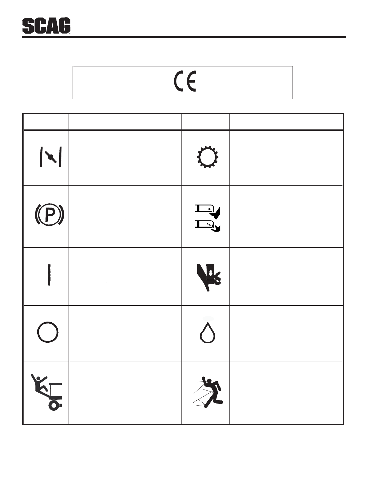
2
CE Mark
TransmissionChoke
On/Start Spring Tension on Idler
Oil
Off/Stop
SYMBOL DESCRIPTION
SYMBOL DESCRIPTION
ISO Symbols
SpinningBlade
48071S
Parking Brake
FallingHazard Thrown Object

3
Slow
Fast
Cutting Element - Engage
Cutting Element - Basic Symbol
Cutting Element - Disengage
Continuously Variable - Linear
Read Operator's Manual
Keep Bystanders Away
Pinch Point
481039S
SYMBOL DESCRIPTION SYMBOL DESCRIPTION
Hourmeter/Elapsed Operating Hours
Thrown Object Hazard

4
SAFETY INFORMATION
GENERAL SAFETY INFORMATION
Your mower is only as safe as the operator.
Carelessness or operator error may result in serious
bodily injury or death. Hazard control and accident
prevention are dependent upon the awareness, concern,
prudence, and proper training of the personnel involved in
the operation, transport, maintenance and storage of the
equipment. Make sure every operator is properly trained
and thoroughly familiar with all of the controls before
operating the mower. The owner/user can prevent and is
responsible for accidents or injuries occurring to
themselves, other people or property.
READ THIS OPERATOR’S MANUAL BEFORE
ATTEMPTING TO START YOUR MOWER.
SIGNAL WORDS
This symbol means “Attention! Become Alert! Your
Safety is Involved!" The symbol is used with the
following signal words to attract your attention to safety
messages found on the decals on the machine and
throughout this manual. The message that follows the
symbol contains important information about safety. To
avoid injury and possible death, carefully read the
message! Be sure to fully understand the causes of
possible injury or death.
A replacement manual is available from your authorized
Scag Service Dealer or by contacting Scag Power
Equipment, Service Department at P.O. Box 152,
Mayville, WI 53050 or contact us via the Internet at
www.scag.com. The manual for your machine can be
downloaded by using the model and serial number or use
the contact form to make your request. Please indicate
the complete model and serial number of your Scag
product when requesting replacement manuals.
If the operator(s) or mechanic(s) cannot read English or
Spanish, it is the owner's responsibility to explain this
material to them.
Signal Word:
The signal word is a distinctive word found on the safety
decals on the machine and throughout this manual that
alerts the viewer to the existence and relative degree of
the hazard.
The signal word “DANGER” denotes that an extremely
hazardous situation exists on or near the machine that
could result in high probability of death or irreparable
injury if proper precautions are not taken.
WARNING:
The signal word “WARNING” denotes that a hazard
exists on or near the machine that can result in injury or
death if proper precautions are not taken.
CAUTION:
The signal word “CAUTION” is a reminder of safety
practices on or near the machine that could result in
personal injury if proper precautions are not taken.
Your safety and the safety of others depends
significantly upon your knowledge and understanding of
all correct operating practices and procedures of this
machine.
BEFORE OPERATION
CONSIDERATIONS
1. Become familiar with the safe operation of the
equipment, operator controls, and safety signs.
2. NEVER allow children or untrained people to
operate or service this machine.
3. DO NOT allow children to ride or play on the
machine, it is not a toy.
4. Clear the area to be mowed of objects that could be
picked up and thrown by the cutter blades.

5
BEFORE OPERATION CONSIDERATIONS
(CONT'D)
C. DO NOT add fuel to a running or hot engine.
Allow the engine to cool for several minutes
before adding fuel.
D. Never fuel the machine indoors or in an enclosed
trailer.
E. Never store the machine or fuel container where
there is an open flame, spark or pilot light such as
on a water heater or other appliances.
F. Never fill containers inside a vehicle or on a truck
or trailer bed with a plastic liner. Always place
containers on the ground away from your vehicle
beforefilling.
G. Remove the machine from the truck or trailer and
fuel on the ground. If this is not possible, then
refuel the machine with a portable container,
rather than from a gasoline dispenser nozzle.
H. Keep the nozzle in contact with the rim of fuel
tankor container opening at all timesuntil fueling
is complete. Do not use a nozzle lock-open device.
I. If fuel is spilled on clothing, change clothing
immediately.
J. Replace gas cap and tighten securely.
5. Always wear appropriate clothing. Loose fitting
clothing, long hair or jewelry could get tangled in
moving parts. Do not operate the machine wearing
shorts; always wear adequate protective clothing
including long pants. Wearing safety glasses, safety
shoes and a helmet is advisable and is required by
some local ordinances and insurance regulations.
8. Before attempting to start the engine, move the
speed adjustment lever into the neutral position, move
the blade engagement switch to the OFF position,
apply the parking brake, and move the neutral latches
to neutral.
9. The discharge chute must always be installed and in
the down position on the side discharge cutter deck
except when the Scag optional grass catcher or
mulching plate are properly installed.
WARNING
WARNING
DO NOT OPERATE WITHOUT DISCHARGE CHUTE, MULCHING
KIT, OR ENTIRE GRASS CATCHER INSTALLED
Always wear hearing protection. Operating
this machine over prolonged periods of time
can cause loss of hearing.
WARNING:
6. Keep the machine and attachments in good operating
condition. Keep all shields and safety devices in
place. If a shield, safety device or decal is defective
or damaged, repair or replace it before operating the
machine.
This machine is equipped with an interlock system
intended to protect the operator and others from
injury. This is accomplished by preventing the
engine from starting unless the deck drive is
disengaged, the parking brake is on, and the speed
adjustment lever is in the neutral position. The
systemshuts off the engine if the operator releases
the operator presence levers with the deck drive
engaged and/or the speed adjustment lever not in
the neutral position, or the parking brake
disengaged. Never operate equipment with the
interlock system disconnected or malfunctioning.
WARNING:
7. Fill the fuel tank with clean, fresh gasoline, with a
minimum octane rating of 87, and up to a maximum
of 10% ethanol. To avoid personal injury or property
damage, use extreme care in handling gasoline.
Gasoline is extremely flammable and the vapors are
explosive.
A. Keep flammable objects (cigarettes, matches,
etc.), open flames and sparks away from the fuel
tank and fuel container.
B. Use only an approved gasoline container.

6
BEFORE OPERATION CONSIDERATIONS
(CONT'D) B. Be alert for holes, rocks, roots and other hidden
hazards in the terrain. Keep away from any
dropoff. Beware of overhead obstructions (low
limbs,etc),undergroundobstacles(sprinklers,
pipes, tree roots, etc.). Cautiously enter a new
area. Be alert for hidden hazards.
10. If the mower discharge ever plugs, shut off the
engine, remove the ignition key, and wait for all
movement to stop before removing the obstruction.
WARNING:
DO NOT operate on steep slopes. To check a slope,
attempt to back up it (with the cutter deck down). If
the machine can not back up the slope without the
wheels slipping, do not operate the machine on this
slope.
ALWAYS travel across the slope whenever possible.
Never up and down the slope.
Reducespeedand usecautionwhenturning,operating
onslopes, slickorwet surfaces. Allowextradistance
to stop.
Operate the machine smoothly, no sudden turns,
starts or stops on a slope.
ALWAYS be sureofyour footing. Keepa firmholdon
thehandles and walk---neverrun.
DONOT mowneardrop-offs,ditchesorembankments.
Themachine couldsuddenlyroll overif a wheelgoes
over the edge or if the edge caves in.
DO NOT permit untrained personnel to operate the
machine.
ALWAYS FOLLOWOSHAAPPROVED OPERATION
7. Disengage power to the cutter deck before backing
up. Do not mow in reverse unless absolutely
necessary and then only after observation of the
entire area behind the mower. If you must mow in
reverse, maintain a constant lookout to the rear of
the machine and mow slowly.
WARNING:
DO NOT use your hand to dislodge the clogged
discharge chute. Use a stick or other device to
remove clogged material after the engine has
stopped running and the blades have stopped
turning.
6. Using the machine demands attention. To prevent
lossofcontrol:
11. Check the blade mounting bolts at frequent intervals
for proper tightness.
OPERATION CONSIDERATIONS
1. Before operating the mower, familiarize yourself
with all mower and engine controls. Knowing the
location, function and operation of these controls is
important for safe and efficient operation of the
mower.
12. Make sure all hydraulic fluid connections are tight
and all hydraulic hoses and lines are in good condition
before starting the machine.
2. Start the engine when the neutral latches are in the
neutral lock position, the cutter blades are disen-
gaged, the parking brake is on and the speed adjust-
ment lever is in the neutral position.
3. Be sure the interlock switches are functioning
correctly.
4. DO NOT mow when children and/or others are
present. Keep children out of the mowing area and in
the watchful care of a responsible adult other than
the operator. Be alert and turn the machine off if a
child enters the area.
5. DO NOT carry passengers.
A. Mow only in daylight or when there is good
artificiallight.
8. Disengage power to the cutter deck before crossing
roads, walks or gravel drives. Stop blades if not
mowing.
9. Shut the engine off and wait until the blades come to
a complete stop before removing the grass catcher
container.
10. Never raise the cutter deck while the blades are
rotating.
7
OPERATION CONSIDERATIONS
(CONT'D)
11. Keep hands and feet away from cutter blades and
moving parts. Contact can injure.
15. Take all possible precautions when leaving the
machine unattended, such as disengaging the mower,
stopping the engine, and removing the key.
13. DO NOT direct the discharge of material toward
bystanders or allow anyone near the machine while
inoperation.
12. DO NOT operate without the side discharge chute
installed and in the down position.
14. If the cutting blades should strike a solid object or the
equipment should start to vibrate abnormally, stop the
engine, disconnect the spark plug wires, and check
immediately for the cause. Vibration is generally a
warning of trouble. Check the machine for damaged
or defective parts. Repair any damage before
starting the engine or operating the cutter deck. Be
sure the blades are in good condition and the blade
bolts are tight.
ROTATING BLADES
NEVER PUTYOUR HANDS INTOTHE DISCHARGE
CHUTEFOR ANY REASON!
8. The engine must be shut off before checking the oil
or adding oil to the crankcase.
MAINTENANCE AND STORAGE
1. Allow only trained personnel to service the machine.
2. Park the machine on level ground.
4. Disengage drives, lower implement, stop engine and
remove key or disconnect spark plug wire(s) to
prevent accidental starting of the engine when
servicing or adjusting the machine. Wait for all
movement to stop before adjusting, cleaning or
repairing.
3. Never make adjustments to the machine with the
engine running unless specifically instructed to do so.
If the engine is running, keep hands, feet, and
clothing away from moving parts.
7. Clean grass and debris from cutting units, drives,
mufflers, and engine to help prevent fires. Clean up
oilor fuel spillage.
5. If the mower must be tipped to perform maintenance
or adjustment, remove the battery, drain the gasoline
from the fuel tank and the oil from the crankcase.
6. Keep all nuts, bolts and screws tight, to ensure the
machine is in safe working condition. Check the
blade mounting bolts frequently to be sure they are
tight. Replace all worn or damaged decals.
CAUTION:
DO NOT touch the engine or the muffler while
the engine is running or immediately after
stopping. These areas may be hot enough to
cause a burn.
DO NOT run the engine inside a building or a
confined area without proper ventilation. Exhaust
fumes are hazardous and contain carbon monoxide
which can cause brain injury and death.
16. DO NOT operate the machine under the influence
of alcohol or drugs.
19. Do not change the engine governor settings or
overspeed the engine. See the engine operator's
manual for information on engine settings.
20. Never leave the machine running unattended.
17. Use care when loading or unloading the machine
onto a truck or trailer.
18. Use care when approaching blind corners, shrubs,
trees, or other objects that may obscure vision.

8
MAINTENANCE AND STORAGE (CONT'D)
9. Let the engine cool before storing.
10. DO NOT store the machine near an open flame.
11. Shut off fuel while storing or transporting.
12. Always store gasoline in a safety-approved, red
container.
13. Use jack stands to support components when
required.
14. Carefully release pressure from components with
stored energy.
15. Use care when checking blades. Wrap the blade(s)
or wear gloves and use caution when servicing
blades. Only replace or sharpen blades. NEVER
straighten or weld blades.
16. Remove sparkplug wire(s) before making any
repairs.
INITIAL RUN-IN PROCEDURES
(FIRST DAY OF USE OR APPROXI-
MATELY 10 HOURS)
4. Check for loose hardware. Tighten as needed.
3. Check the tires for proper pressure.
Caster Wheels Flat Free
Drive Wheels 12psi.
2. Check the steering control rods for neutral
adjustment (See Adjustments, page 12).
1. Check the belts for proper tension at 2, 4 and 8
hours. Adjust as needed.
5. Check the safety switches for proper adjustment.
6. Apply lubricant to all the grease fittings.
Lubricant was applied at the factory. This is just a
precautionary check to make sure that all the
fittings have been lubricated.
MOWER OPERATION
1. Read and understand the safety instructions before
attempting to operate this machine.
2. Before starting the engine:
* Check the oil level in the engine and the hydraulic
reservoir.
-NOTE-
Use gasoline with an octane rating no less than
87 and a maximum of 10% ethanol.
* Fill the fuel tank with clean, fresh, lead-free
gasoline.
* Open the fuel valve on the bottom of the fuel
tank.
* The operator's presence levers must be released.
* The speed adjustment lever must be in NEUTRAL.
* The blade clutch switch must be in the OFFposition.
* The neutral latches must be in the neutral lock position.
* Cold starting. In the spring and fall when the
morning temperatures are cool it may be difficult
to start the machine due to the parastatic load
fromthe hydraulic drive. To relieve thisload, pull
out and up on the de-clutch chain located on the
right side of the machine behind the tire. This will
allow you to start the engine easily. When the
engine is warmed up, slowly release the de-
clutch chain to engage the hydraulic system.
* The key switch must be on.
3. Start the engine:
* Choke as required. If the engine is cold, pull the
choke knob out. When the engine starts, slowly
push the choke in. If the engine stalls, repeat the
above operation. When the engine is warm,
choking may not be necessary.
4. Engage the cutter blades by depressing the operator
presence levers and pulling the blade clutch switch
into the ON position. Push the switch to the OFF
position to disengage the cutter blades.
* The parking brake must be on.

9
MOWER OPERATION (CONT'D)
8. When the steering brake levers are released, the
machine will travel straight. To make a right turn,
squeeze the RH lever. To turn left, squeeze the LH
lever.
9. TO STOP, squeeze both levers, lock the neutral
latches, and move the speed adjustment lever to
neutral.
10. To move the machine in reverse, squeeze up on both
steering control levers.
5. Engage the cutter blades by pulling the blade clutch
switch into the ON position. Push the switch to the
OFF position to disengage the cutter blades.
390S0138
PULL UP TO ENGAGE
PUSH DOWN TO DISENGAGE
-NOTE-
When PTO is engaged or (possibly) disengaged,
a squealing sound from the underside of the
machine is normal. It is caused by the electric
clutch plates meshing as the mower comes up to
speed. For best equipment life, engage the
clutch with the engine at 3/4 throttle, not under
full load.
WARNING:
If you are not familiar with the operation of the
hydrostatic drive and zero turn feature, practice
turning and maneuvering with the hand controls
beforeengagingthecutterblades.
7. While squeezing the steering brake levers with both
hands, release both neutral latches.
-NOTE-
Top speed is suggested only for transport!
6. Release the parking brake. Move the speed adjust-
ment lever to the desired mowing speed.
11. To "freewheel" or move the machine around
without the engine running, turn the dump valve
levers located at the back of the pumps to the
"freewheel" positions (see Figure 1). To operate
the machine, the dump valve levers must be
returned to the closed positions.
Figure 1. Dump Valves
SWZ05DMPVL
V
Dump Valve Levers
(closed position)
BELT TENSION
Stop engine and remove the key from the ignition
beforemakinganyadjustments.Waitforallmoving
partstocometoacompletestopbeforebeginning
work.
CAUTION:
-NOTE-
All the belts on the SWZU are spring-loaded and
do not require adjustment. Check the belts for
excessive wear or damage daily for the first week.
After the first week, check the belts monthly.
1. Remove the belt covers.
2. Inspect the belts for wear, cracking, or glazing.
Contact your Scag dealer if any unusual wear is
noted.
3. Replace the belt covers.

10
5. Turn the deck support pins to lengthen or shorten
the pins to reach the desired result.
6. Tighten the jam nut, replace the hair pin, and
remove the blocks. Check that the desired deck
pitch is achieved.
CUTTER DECK ADJUSTMENTS
Due to the many cutting conditions that exist, it is difficult
to suggest a cutter deck setting that will work for every
lawn. There are two adjustments that can be made on
these decks, pitch and height.
PITCH is the angle of the blades in relation to the ground
(comparing front to rear). The pitch of the cutter blades
should be equal between the front and rear for proper
cutting performance. To check for proper deck pitch, be
sure that the mower is on a flat, level surface and the
tires are properly inflated.
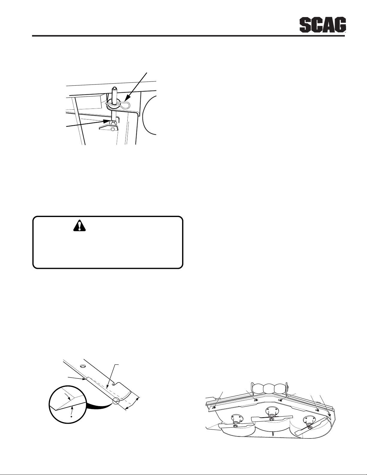
Figure 2. Cutting Height Adjustment
The cutter deck pitch adjustment has been set at the
factory and normally will not need to be changed.
However, if the pitch needs to be adjusted due to service
work performed on the deck, follow the procedure below
(see Figure 3, Page 11).
1. Shut off the engine and remove the key.
2. Support the cutter deck with four blocks (you
will be removing the hair pins to make this
adjustment).
3. Remove the front hair pins from the front deck
supportpins.
4. Loosen the jam nuts on the deck support pins.
CUTTER DECK PITCH ADJUSTMENTS
Remove Hair Pins SWZU05DHA
HEIGHT is the nominal distance the blade is off of the
ground. This measurement is made with the blades
pointed side to side and distance is measured between
cuttingtipand ground.
Changes to the cutting height can be achieved by reposi-
tioning the cutter deck. There are eight available posi-
tions from 1" to 4-1/2" (See Figure 2).
Do not adjust the cutting height with the mower
blades rotating. Shut off the engine and remove
the ignition key. Bodily injury could occur from
the rotating blades.
WARNING:
4. Repeat the above process on the opposite side of the
cutter deck.
1. Shut off the engine and remove the ignition key.
2. While holding up on the deck support handle, remove
the two hairpins from the adjusting pins on one side
of the cutter deck (See Figure 2).
3. Lift or lower the deck to the desired cutting height
and reinstall the hairpins. Adeck height decal is
located on the deck mounting frame as an aid in
adjusting the deck to the desired height.
11
CUTTER DECK ADJUSTMENTS (CONT'D)
SWU99PA
REMOVE HAIR PIN
LOOSEN
JAM NUT
Figure 3. Deck Pitch Adjustment
CUTTER BLADES
Do not sharpen beyond 1/3 of the width of the blade.
(See Figure 4).
-NOTE-
Dress the blade with a file. Using a wheel
grinder may burn the blade. Check the balance
of the blade. If blades are out of balance, vibra-
tion and premature wear of spindle assembly can
occur. See your authorized Scag dealer for
blade balancing or special tools, if you choose to
balance your own blades.
WARNING:
Bladeshaveasharpcuttingedge.Wearproper
eyeprotection andprotectiveglovesorwrap
bladeswithprotectivematerialwhenremoving,
sharpeningand installing blades.
Figure 4. Blade Sharpening
SGB033
Angle Blade Back
Do Not Cut In
X Must NOT Exceed
1/3 Blade Width
X
30
Custom-Cut Baffle Adjustment
The Custom-Cut Baffle is designed to deliver optimum
airflow and superior cutting performance in any type of
grass. The Custom-Cut Baffle can be raised or lowered
to precisely tailor the deck's performance for the type of
grass being cut. The baffle can be set in three (3)
different positions for optimum performance.
A. 3" Position - baffle is installed using the top set of
holes on the front baffle welded inside the cutter
deck. (See Figure 6, Page 12). The Velocity-Plus and
Advantage cutter deck will deliver the best quality-
of-cut in very tall, wiry, tough to cut grass.
B. 3-1/2" Position (factory setting for advantage cutter
decks) - baffle is installed using the middle set of
holes on the front baffle welded inside the cutter
deck. (See Figure 7, Page 12). For general purpose
cutting, place the Custom-Cut Baffle in the 3-1/2"
position. This gives the best mix of cutting
performance in all types of grass.
C. 4" Position (factory setting for Velocity-Plus cutter
decks) - baffle is installed using the bottom set of
holes on the front baffle welded inside the cutter
deck. (See Figure 8, Page 12). Placing the baffle in
the 4" setting will enhance fall cutting (leaf pickup)
and reduce cutter deck "blowout".
To Adjust the Custom-Cut Baffle height:
1. Remove the hardware securing the Custom-Cut Baffle
to the cutter deck (See Figure 5).
Figure 5. Custom-Cut Baffle
2004 CCB
MOUNTING
HARDWARE MOUNTING
HARDWARE
Hardware location used in the illustrations are for
reference only. Location of hardware may vary
depending on the cutter deck size.
-NOTE-

12
NEUTRAL ADJUSTMENT
-NOTE-
Neutral has been set by your Scag dealer at the
time of setup and normally does not need to be
adjusted. If, however, you find that the neutral
has come out of adjustment, follow the procedure
below.
1. Raise the drive wheels off the ground and block the
caster wheels to prevent the machine from moving.
2. Make sure the speed control lever is in neutral, the
steering control levers are in the neutral latch position,
and the parking brake is on. Start the engine.
3. Release the parking brake and note if the tires are
rotating.
4. Starting on the left side of the machine, using the
adjustment wrench located on the left side of the
machine. Rotate the tracking adjustment nut counter
clockwise just until the LH wheel starts to creep
forward. Make a note of the position of the adjust-
ment nut. (See Figure 9).
5. Turn the adjustment nut clockwise just until the wheel
turns rearward. Make a note of the position of the
adjustment nut. To adjust neutral, split the difference
between the two noted positions of the adjustment
nut. Repeat on the right side as needed.
6. Place the wrench in the holder on the left side of the
machine and turn the engine off.
Figure 8. 4" Custom-Cut Baffle Position
BOTTOM SET OF HOLES
FOR 4" SETTING
2004 CCB - 4" Setting
CARRIAGE BOLT
ELASTIC STOP
NUT
CUSTOM-CUT BAFFLE ADJUSTMENT
(CONT'D)
2. Move the Custom-Cut Baffle to desired position. (See
Figures 6 through 8 for position).
3. Reinstall the mountinghardwareasshown.(See Figures
6 though 8). Torque hardware to 39ft.lbs.
Figure 6. 3" Custom-Cut Baffle Position
Figure 7. 3-1/2" Custom-Cut Baffle Position
TOP SET OF HOLES
FOR 3" SETTING
2004 CCB - 3" Setting
CARRIAGE BOLT
ELASTIC STOP
NUT
MIDDLE SET OF HOLES
FOR 3-1/2" SETTING
2004 CCB - 3-1/2" Setting
CARRIAGE BOLT
ELASTIC STOP
NUT
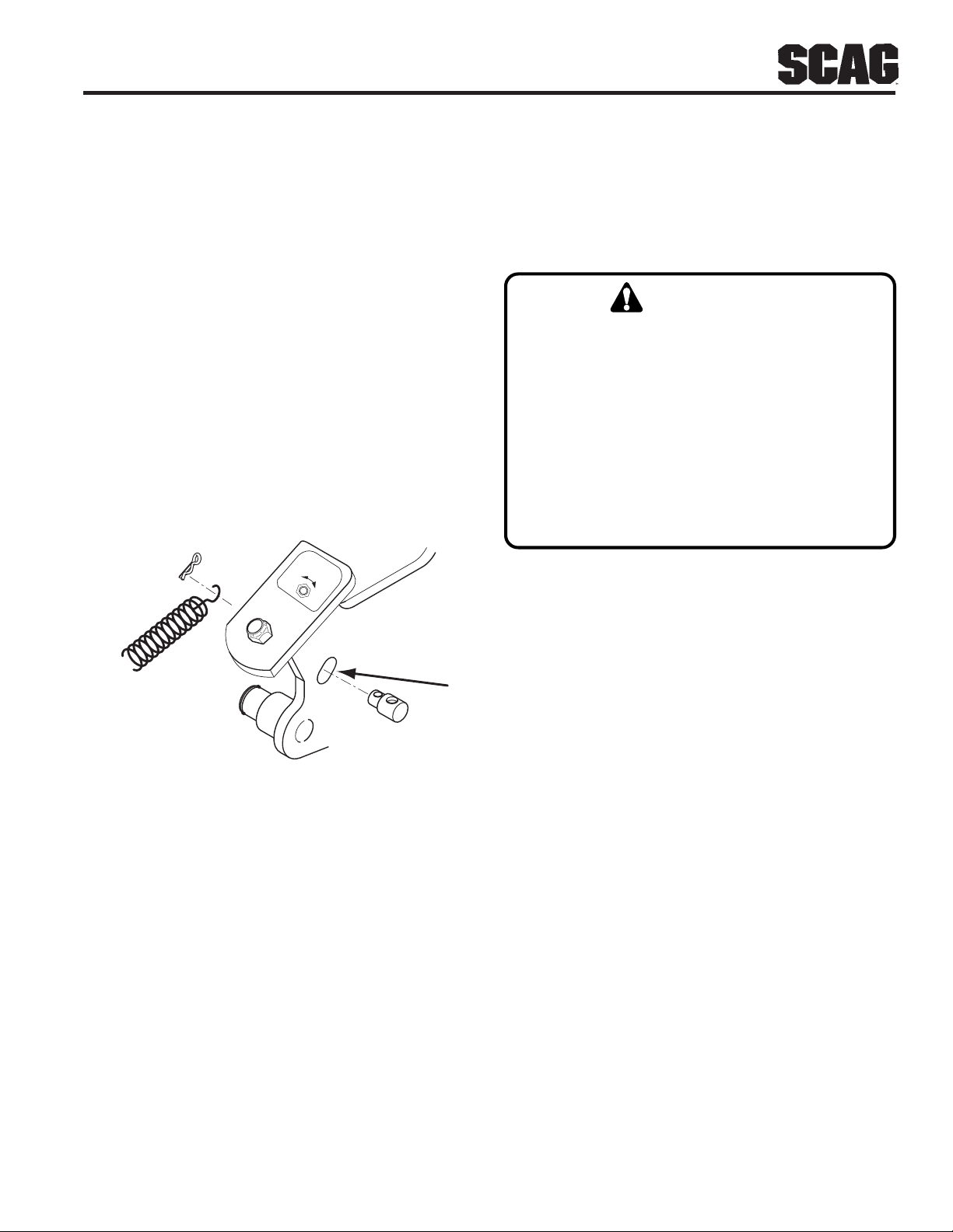
Figure 9. Neutral Adjustment
13
STEERING CONTROL ROD
ADJUSTMENT -NOTE-
This adjustment is made to allow the steering
control levers to be moved out of the neutral
latch without engaging reverse.
Before making this adjustment be sure that the
speed control bearing is just touching the speed
control cam and that the bellcrank bearing is
resting in the center groove of the neutral cam.
1. Remove the speed control spring. Remove the
steering control rod swivel hair pin. Check the
location of the swivel in the slotted hole in the bell
crank.
2. Turn the swivel joint on the steering control rods until
the swivel joint is centered in the slot in the bellcrank.
3. Reinstall the speed control spring onto the swivel.
Install the hair pin onto the swivel. (See Figure 10).
Figure 10. Control Rod Adjustment
SLOW
FAST
TRACKING
ADJUSTMENT
SEE OPERATOR'S
MANUAL
390s0198-1
TRACKING ADJUSTMENT
-NOTE-
Before proceeding with this adjustment, be sure
that the tire pressures are correct, (see page 8)
and that the neutral adjustment and the steering
control rod adjustment have been completed.
1. With the machine on a flat level surface, start the
engine and place the speed adjustment lever into the
speed that will most often be used.
2. Squeeze the steering control levers and release the
neutral latch. Slowly release the steering control
levers, allowing the machine to move forward.
WARNING:
BEFORE ATTEMPTINGTO MAKE ANYTRACKING
ADJUSTMENTS:
1. Move the speed adjustment lever to the
neutral position.
2. Place the blade engagement switch in the
OFF position.
3. Apply the parking brake.
4. Move the steering control levers into the
neutral position.
3. If the machine pulls to one side, stop the mower by
placing the steering control levers in the neutral
position. Using the adjustment wrench located on the
left side of the machine, turn the tracking adjustment
nut on the slower side counter clockwise until the
machine tracks straight. (See Figure 11, Page 14).
4. Bring the steering control levers back to the neutral
lock position and check to see that the machine does
not creep forward on the adjusted wheel.
5. If the machine creeps in neutral you have moved out
of the neutral band and will have to turn the tracking
adjustment nut clockwise until the machine does not
creep.
6. Repeat steps 1 and 2. If the machine continues to
pull to one side, stop the mower by placing the
steering control levers in the neutral position. Turn
the tracking adjustment nut on the faster side clock-
wise until the machine tracks straight.
7. If tracking cannot be achieved, contact your Scag
servicing dealer.

14
Section 3
TRACKING ADJUSTMENT (CONT'D)
Figure 11. Tracking Adjustment
PARKING BRAKE
1. Adjust the parking brake so that when the brake
hand lever is against the stop on the handle bar, the
brake levers on the brake shaft weldment are
against the stops on the engine deck.
2. Adjust the brake actuator rod on either side of the
machine to obtain proper brake adjustment.
CAUTION:
Adjust the brake only enough to hold the
machine. Excessive force may cause damage to
themachineor brake components.

15
LUBRICATION & MAINTENANCE
X Check all hardware for tightness
X Checkall beltsfor properalignment
X Checkengineoillevel See engine operator's manual
X *Cleanaircleanerelement See engine operator's manual
X Check operator presence system See page 5
X Check tire pressure See page 8
X Check belt tension See page 9
X Sharpen cutter blades See page 11
X Checkhydraulicoillevel See page 16
X *Cleanmower See page 17
X Change engine oil and filter See engine operators manual
X Grease spindle bearings +USLithiumMPWhiteGrease2125
X Checkhydraulicoillevel See page 16
X Change engine oil See engine operator's manual
X Checkall beltsfor properalignment
X *Replaceairfilterelement See engine operator's manual
X Grease caster wheel bearings Chassis grease
X Check all hardware for proper tightness More often if needed
X Grease brake hand lever Chassis grease
X Grease brake actuator levers Chassis grease
X Drain hydraulic systemand replaceoil & filter See page 16
X Grease caster wheel pivot shafts ** Chassis grease, see instructions below
X Replaceenginefuelfilter See engine operator's manual;
X Adjust air gap on electric clutch Contact your Scag dealer for information about
this maintenance procedure.
BREAK-IN
8HOURS(DAILY)
20HOURS
40HOURS(WEEKLY)
100HOURS(BIWEEKLY)
500HOURSORANNUALLY
COMMENTS
PROCEDURE
+Greasespindleuntilgreasecomesoutthereliefvalve.
CompatibleGreases: LidokEP#2(foundatindustrialshops)
RonexMP(Exxonservicestations)
ShellAlvania(Shellservicestations)
Mobilux#2(Mobilservicestations)
SuperLubMEP#2(Conocoservicestations)
* Perform these maintenance procedures more frequently under extreme dusty or dirty conditions.
**PROCEDURE: Remove grease cap, part number 481559. Remove plug, part number 482028-01, and install
standard grease zerk (p/n 48114-06). Apply grease to the fitting until new grease appears at the top of the
caster extension. Remove the grease zerk and reinstall the plug. Reinstall the grease cap. Special tool, part
number 47007, is recommended for use in the installation of the grease cap.

16
HYDRAULIC SYSTEM
Checking Hydraulic Oil Level
-IMPORTANT-
correct immediately.
If the oil level is consistently low, check for leaks and
1. Wipe dirt and contaminants from around the
reservoir cap. Remove the cap from the hydraulic oil
reservoir.
2. Visually check the level of hydraulic oil. Hydraulic oil
must be at least 2 inches from top of the filler neck.
If the level cannot be determined visually, use a clean
tape measure to check the level. If the fluid is low,
add 20W50 motor oil. DO NOT overfill; (overfilling
the oil reservoir may cause oil seepage around the
cap area).
3. Clean the fill cap and install it onto the reservoir.
The hydraulic oil level should be checked after the first 8
hours of operation. Thereafter, check the oil every 100
hours of machine operation or monthly, whichever occurs
first.
Changing Hydraulic Oil
The hydraulic oil should be changed after every 500
hours or annually, whichever occurs first. The oil should
also be changed if the color of the fluid has become
black or milky.Ablack color and/or a rancid odor usually
indicates possible overheating of the oil, and a milky color
usually indicates water in the hydraulic oil.
2. Place a suitable container under the hydraulic oil
drain. Remove the fill cap from the reservoir.
Remove the drain cap from the T-Fitting located on
the hydraulic system filter head. (See Figure 12).
Allow the fluid to drain into the container and
properly discard it.
3. Reinstall the drain cap onto the T-Fitting and be sure
itis tight.
Figure 12. Hydraulic Oil Drain Cap
Hydraulic Oil
Drain Cap
2003SWZ-Oil Drain
Filter Head
Hydraulic Oil
Filter
1. Park the mower on a level surface and stop the
engine.
Changing Hydraulic Oil Filter Element
The hydraulic oil filter should be changed after every 500
hours of operation or annually, whichever occurs first.
1. Remove the oil filter element (Figure 12) and
properly discard it. Fill the new filter with clean oil
and install the filter. Hand tighten only.
-NOTE-
The hydraulic oil should be changed if you
notice the presence of water or a rancid odor
to the hydraulic oil.
-NOTE-
Before refilling the hydraulic oil reservoir the
hydraulic oil filter should be changed as well.
See instructions outlined below.
4. Fill the reservoir to 2 inches from the top of the filler
neck with 20W50 motor oil.
5. Replace the reservoir fill cap. Start the engine and
drive forward and backward for two minutes.
Check the oil level in the reservoir. If necessary, add
oil to the reservoir.
This manual suits for next models
4
Table of contents
Popular Lawn Mower manuals by other brands

Craftsman
Craftsman EZ3 917.271011 owner's manual

MTD
MTD 074 Series Operator's manual

Caiman
Caiman Ambrogio L300 Installation course
Flymo
Flymo Chevron 32VC operating instructions

Craftsman
Craftsman 247.375910 Operator's manual

Craftsman
Craftsman 28970 - Professional PYT 24 HP/42" Yard... Operation manual


Stanley
Stanley 100TS owner's manual

Schiller Grounds Care
Schiller Grounds Care Bob-Cat CLASSIC PRO 932007G parts manual

BEST PRICE
BEST PRICE BM 42 manual

Jacobsen
Jacobsen HF-5 Operation and maintenance

Gravely
Gravely 992224 Owner's/operator's manual

Craftsman
Craftsman LAWN TRACTOR 917.27105 owner's manual