Caiman Ambrogio L300 Installation and operation manual

- 1 -
I
In
ns
st
ta
al
ll
la
at
ti
io
on
n
C
Co
ou
ur
rs
se
e
V
V.
.
2
20
01
10
0
L
La
aw
wn
n
M
Mo
ow
we
er
r
R
Ro
ob
bo
ot
t
Installation ...................................................................................................................................................... 2
To remind before the installation ................................................................................................................... 7
Robot Programming ....................................................................................................................................... 8
Upgrade and Connection – Mother Board ................................................................................................... 12
Display Board Connection (200Z04600A) ..................................................................................................12
Robot Software Update ................................................................................................................................ 13
Service Menu................................................................................................................................................ 16
Service Menu - (Release November 2009) .............................................................................................. 16
Service Menu: “Statistics”........................................................................................................................ 17
Service Menu: “Test Motors”................................................................................................................... 17
Service Menu “Battery Type” .................................................................................................................. 18
Service Menu “Test Tilt” ......................................................................................................................... 18
Service Menu “Test Bump” ..................................................................................................................... 18
Service Menu “Blackout”......................................................................................................................... 18
Service Menu “Border Blade”.................................................................................................................. 19
Errors displayed by the robot and related causes ......................................................................................... 20
Meaning of the leds during the starting up.......................................... Error! Bookmark not defined.
Meaning of the leds while the robot is working................................... Error! Bookmark not defined.
Summary sheet ......................................................................................... Error! Bookmark not defined.
Advanced problems...................................................................................................................................... 26
01
-------
2010

- 2 -
Installation
Preliminary Remarks
Maximum Covering suggested We must check the maximum Sm suggested for each model, also on the base
of the installed batteries. However it is a good rule not to exaggerate and
keep in mind that on more complicated gardens, with different separated
areas the Sm covered by the robot are reduced.
Maximum slope: 27°
This is the maximum slope achieved by the robot.
Remember that the main problem is the slope because when the robot
reaches the cable it is not able to come back. In order to improve the
performance of the robot, it is useful to set the spiked wheels on the machine
if possible.
Before starting the installation we suggest you to have a test on a slide. In the
user’s menu, set out the option Border “NO”, set the robot on a slide, let it
feel a bump on the body and test that it doesn’t slide while reversing or
changing direction.
Secondary Areas Management. The robot manages the main area and three secondary areas as well
(according to models). With “secondary area” we mean a part of the garden
connected to the main one thanks to a narrow passage and which can hardly
be reached by chance. Saying if the passage is large or narrow for the robot
depends on the primary area dimension.
Recharge of the robot First of all put the robot in charge. At the end of the installation, it will be
useful in order to test the correct operating.
Arranging the garden
It is necessary to inform the customer about how to prepare the garden
before the installation. The most common problems are small holes, small
toys, stones, or all the objects that the robot can not recognize as an obstacle
and that consequently might pass under the covering and be hit by the blade.
Watering System Pay attention to the watering system! It is necessary to understand where the
irrigators are and place the recharging base in a safe part of the garden, far
from the irrigator that might wet the robot and especially the display side.
Recharging Base
It is maybe the most difficult decision to
take. The recharging base must be
positioned according to some exact rules.
The recharging base must be positioned
on a:
- Plan area
- Firm ground
- In the widest area (if there is a
big difference of square meters)
Better but not compulsory.
- Not nearby an irrigator
- Before the recharging base
there must be 2 mt of straight perimeter cable
- Not nearby an electric gate because of interferences
The recharging base must be well fixed to the ground and it is
necessary to pay attention to the entrance step. There must not
be any step. The problem can be solved by clearing away the
grass surface or by putting an artificial grass mat in front of the
recharging base, which makes easier for the robot to enter the
station.
Transformer The Transformer must be placed according to the following rules:

- 3 -
- Place it in an area protected from water.
- Better to put it indoors.
- If it is placed outside, please put it in a ventilated box and not
exposed to sun or water.
- It would be better to put it in a refreshed area.
- It must be outside the garden and not inside it.
- It must be at least 2-3 meters from the recharging base.
- The cable connecting the transformer to the recharging base must
not be twisted, but it has to be spread so as not to create any
magnetic field.
- Do not shorten the cable.
- Do not lengthen the cable.
How to install the perimeter cable
After deciding where to place the recharging base it is possible to install the
perimeter cable. To install it, it is necessary follow some rules:
- For the first times, we suggest installing the perimeter cable on the
ground rather than burying it. After some weeks, it will be soaked
up by the ground. (The first weeks the blade has to be about 5 cm
higher than the usual). Once become more experts, the best
installation is the one made with the Wire layer machine.
- Start with the black connector. Follow the cable-trace on the
recharging base and come out with the cable from the rear side of
the base.
- It is suggested to leave a cable store for possible future
modifications in front of the base and behind it (to create this store
it is necessary to make a flowerbed and leave cable intermingled
with the cable delimiting the surface)
- Work in a clockwise direction
- Remember to position properly the
fast returns to the base or “Arrows”
(see next paragraph).
- When there is a flowerbed the
installation has to be made
anticlockwise. If you make a mistake,
the robot feels the flowerbed before reaching the cable.
- If there are two flowerbeds close to each other, you shall lay the
cable passing from one to the other.
- Respect the following distances:
oSidewalk at the same grass
height : 0-5Cm
oWall 35 Cm
oHedge 35 Cm
oSwimming pool, Hole,
Precipice 80 Cm
- As far as possible, all the bents must
not be done like a 90° angle.
- Every connection must be made with proper material like the 3M
self stretching tape “scotch 23”.
- It is suggested to leave a cable store for possible future
modifications in front of the base and behind it (to create this store
it is necessary to make a flowerbed and leave cable intermingled
with the cable delimiting the surface).
- in front of the base, the cable must be positioned straight for the
total length of 2 meters.
- The extra cable must not be left gathered.
- At the end of the installation it is necessary to connect the going in
of the cable to the red connector.
- The maximum cable length is 600mt +- 20%. By means of the
“Border Powered” it can reach 1000mt+-20%.

- 4 -
- Leave the robot at least 1 meter away from the point where the
robot makes the signal synchronization (when it comes out of the
base it turn with an angle of 90°)
Quick Return “Arrows”
Arrows measures.
Model: Ambrogio L300
Model: Ambrogio L200
The quick return or “Arrow” is a perimeter cable symbol recognized by the
robot in order to come back quickly to the recharging base. There are many
advantages:
- The robot goes back to the recharging base earlier, so there is a
lower consumption of batteries.
- The robot goes back earlier to the recharging base and resumes
quickly mowing the lawn again.
- There are fewer traces on the ground.
The first picture aside shows the installation without arrows, the second one
shows the installation with arrows. As you can see the route made by the
robot is shorter. We recommend to position the arrows as shown in the
second picture.
An arrow is often put shortly after the recharging base because, if the robot
fails to enter the base, it returns quickly to recharge again.
Remember that the robot recognizes consequently a maximum of three
arrows each working cycle.
IMPORTANT!!!!!. Never put an arrow in the return way otherwise the
robot never comes back to the recharging base.
IMPORTANT!!!!. Once the installation is completed and the perimeter cable
is connected, check that the transformer and the transmitter are working
properly.
Transmitter Led Explanation:
Flashing Yellow : Border Ok.
Steady Green : Interrupted or not connected border
Steady red : Robot is charging. Signal is not transmitted
Switched off Led : Not connected Battery Charger, Faulty fuse in the
transmitter, Faulty Transmitter
Battery Charger Led Explanation:
Steady Green : Working Battery charger
Steady red : Working Battery Charger with batteries in fast charge.
Off : Switched off or faulty Battery Charger.
IMPORTANT!!!!!. The measures are approximate. Sometimes and
especially in case of sliding, it is recommended to increase the measure with
some more cms. It would be helpful to test the correct recognition with not
completely charged batteries and therefore in the same conditions occurring
while the robot is normally working.

- 5 -
Secondary Area
The secondary area is a part of the garden connected to the main garden by
a narrow passage that is hard to be achieved by chance. Saying if the passage
is big or small for the robot depends on the primary area dimension.
Obviously the secondary area must be at the same level of the primary area
(without steps).
The robot can manage up to three secondary areas (the primary and three
secondary areas).
The minimum passage is 70 cm from cable to cable. So the passage that you
need is 1 meter and 40 cm wide. It is better to increase the distance if the
passage is very long. On the contrary, if the passage is shorter than 2 meters,
we can venture some centimeters less.
During the programming it is necessary to set in the robot the dimensions of
the secondary areas with percentage in relation to the lawn and to the best
way for the robot to reach them faster (clockwise/anticlockwise), and
obviously in relation to the meters the machine has to follow the cable in
order to reach the secondary area.
Closed secondary area
The secondary area is a part of the garden separated from the main area but
connected to it with the going in and out of cable.
The robot must be carried to the closed area by hand and it must be taken
again to the primary area to recharge its batteries.
These solutions do not fit big gardens because the management will be
difficult.
In fact the robot cannot fulfill the charging cycle completely and the
mulching effect is not completely successful because it is highly probable that
the customer won’t punctually move the machine from one area to the other
or may forget to do it.
In order to tell the robot that it is working in a closed area, it is necessary to
switch it on in the closed area. Push "Enter" to enter programming mode.
Scroll voices up to "WORK MODE". Set "NO PERIMETER" and
set Robot working minutes.
From this moment on the robot knows that it is in a closed area and that
when it finishes working it must not look for the recharging base but has to
stop.
Installation without perimeter It’s possible to let the robot work even without a border. We do not suggest
this option. It is normally used for demonstrations only or for small gardens
situated near the main lawn and completely delimited by fences (even the
flowerbeds).
Installation of neighboring perimeters
Situation : 1 – Solution “A”
Situation 1: (Same owner with 2 different and separated gardens not
accessible to the same robot)
- In these situations there are 2 different solutions.
- Solution “A”. Have only one installation of the garden 1 and 2 by
linkin
g
the 2
g
ardens to
g
ether. The rechar
g
in
g
base in
g
arden no 1

- 6 -
Situation 1 – Solution “B” and Situation 2
Situation : 3
is connected as usual. The recharging base in garden no 2 is placed
on the border wire without connecting the cable to the black and
red connector.
ATTENTION!!!. Robot transmitter “1” must have the DIP-
SWITCH 1 ON, to transmit even when robot 1 is in its recharging
base
Advantages:
oNo change must be done with the robots you have.
oIn case of failure of the robot in garden no 1, the robot no 2
can be taken to garden 1 and there put at work.
Disadvantages
oThe length of the border wire can be excessive. Please keep
in mind the limit is 600MT, beyond that limit the (48V)
signal amplifier is required.
oIf the border wire is interrupted both the robots stop.
oAn extra battery charger can be necessary. The one given as
equipment is used to supply the signal transmitter, the other
one charges the batteries of the robot.
- Solution “B”. Have two normal and different installations
Advantages:
oIf the border wire is interrupted only one robot stops.
oThere are no problems in finding a passage to connect the 2
gardens.
Disadvantages
oThe B channel (receiver + transmitter) must be installed in
the robot no. 2
oIn case of failure of one robot, the other one cannot be used
to mow the zone 1 as well.
Situation 3: (Installation of Ambrogio when in the closest garden there is a
robot by another manufacturer installed).
1. AMBROGIO ROBOT :
a-) If possible leave the dip-switch 1 on OFF (signal stop while the
robot is in recharging base)
b-) Activate on transmitter a channel different from the one used in
the other robot and install the relative channel receiver, that must
be selected on the robot menu as well.
d-) Leave a distance of 60-90 Cm between the two gardens. If the
robot of the adjacent garden is a old generation Ambrogio with
“Standard” or “RX” signal, it is necessary to leave a distance of
120Cm.
2. FRIENDLY:
a-) If possible leave the dip-switch 1 on OFF (signal stop while robot
is in its recharging base)
b-) Activate Channel “C” on transmitter and install C receiver on
the robot menu as well.
c-) If possible, reduce the power of our transmitter mofifying the
Dip-Switch.
d-) Leave a distance of 120Cm between two gardens.
3. AUTOMOWER:
a-) If possible leave the dip-switch 1 on OFF (signal stop while the
robot is in recharging base)
b-) Activate Channel “A” on transmitter and install A receiver on
the robot menu as well.
c-) If possible, reduce the power of our transmitter modifying the
Dip-Switch.
d-) Leave a distance of 120Cm between the two gardens

- 7 -
To remind before the installation
You have to keep in mind that :
Before the installation : Have You cut the garden before the installation, especially the edges?
Is there a socket preferably in the widest area?
How wide is the garden? check the model specification and the batteries
provided
During the installation Put the robot into charge on “PAUSE” modality.
Check the slides, by trying the robot with the option No Border.
Secondary areas. We manage the main area and three secondary areas.
(according to models)
Decide where to install the recharging base
- “Preferred” Widest area but not compulsory.
- Socket
- Flat area
- Water system
Check the water systems position.
At the end of the installation Settle the rain sensor
Test how the robot follows the border cable
• (With the key– Switch the blade off)
Test the recognition of the arrows.
●(With not too charged batteries)
●With the key “CHARGE” you simulate low batteries.
Program the working times of the Robot. (Pay attention to the working times
of the irrigators).
Inform the customer that he has to set out a password.
Leave the blade at 5-6 Cm and inform the customer that he has to lower it
when the border cable has been absorbed.
Hooked wheels (if the model robot allows this). It would be helpful not to
install them until the border cable has been absorbed by the ground.

- 8 -
Robot Programming
Programming and other.
Explanation of the keys
“ON” : To switch the robot on.
“OFF “: To switch the robot off.
“STOP-EMERGENCY“ : It is needed to switch the robot off in case of
emergency. We must use this key in case of emergency and when we need to
work on the cutting motor. In order to restart the robot, we must press it
once again. The emergency Led will switch off . Then it is possible to switch
it on again by pressing on the key ON.
“PAUSE”: To put the robot in Pause mode or to resume working.
“CHARGE”: To make the robot come out while is in the recharging base. To
let it enter the recharging base while working.
“-“: To change the values during the programming. To turn off the blade
while the robot is working.
“+ “: To change the values during the programming. To turn the blade on
while the robot is working.
“ENTER”: To confirm the choice during the programming. To activate the
spiral while the robot is working.
Programming Menu
To enter the programming menu, it is necessary to put the robot in
“PAUSE” and push “ENTER”. The menu consists in menus and under
menus. With the key “+” and “-“ you can scroll the menu entries or change
the value displayed. With the “ENTER” key, you can select the entry, enter
the under menu or confirm the displayed value.
Here below only the most correct parameters for a proper functioning are
listed:
- Working days: For every working day, it is possible to show with
“1” if the robot must work and with “0” if not. The robot must
work every day or every other day to exploit the mulching effect.
- Working hours : It is possible to plan two working hours to make
the robot come out. Always remember that in order to charge the
batteries the robot needs from 3.5 to 4 hours. So between the
working time 1 and the working time 2 this break will be necessary.
- Secondary area 1 _ Dimension % : it allows to set out the dimension
of the secondary area in relation with the entire surface.
o20% Indicates a very very small area.
o30% Indicates an area which is approximately ¼ of the
whole garden.
o50% Indicates an area, which is approximately the half of
the whole garden.
o80% Indicates a secondary area which is bigger than the
primary area.
o100%. Every time the robot goes out of the docking station,
it will follow the border cable to mow the secondary area.
- Secondary area 1_Direction: it indicates the fastest direction to
follow in order to reach the secondary area. The direction can be
both clockwise and anticlockwise. Coming out the recharging base,
the robot will follow the cable according to the settled direction in
order to cut in the secondary area.
- Secondary area 1_Distance: it allows to set out the distance (in
meters) the robot needs to reach the secondary area, following the
perimeter cable. It is recommended to measure the distance on the
half of the secondary area, so that you can be sure that the robot
will be in the secondary area when it starts mowing.

- 9 -
- Secondary area 2: This is like the previous options but for the area
number 2
- Secondary area 3: This is like the previous options but for the area
number 3
Work and Programming example of the
secondary area.
Examples of programming the work-cycles.
Model: Ambrogio L300
Sq. mts. time 1 time 2
0400Sq mts 10:00 - 11:30
0800Sq mts 10:00 - 13:00
1200Sq mts 10:00 - 14:00
2000Sq mts 10:00 - 13:00 17:00 - 20:00
3000Sq mts 09:00 - 13:00 17:00 - 21:00
4000Sq mts 08:00 – 13:00 17:00 - 22:30 (4 Lithium Batteries)
5000Sq mts 07:00 – 13:00 17:00 - 23:00 (4Lithium Batteries)
Model : Ambrogio L200
Mq time 1 time 2
0200Mq 10:00 - 11:00
0500Mq 10:00 - 12:00
0900Mq 10:00 - 11:30 16:00 - 17:30
1200Mq 10:00 - 12:00 16:00 - 18:00
1500Mq 10:00 - 12:00 16:00 - 19:00
2000Mq 08:00 - 21:00
2500Mq 08:00 - 22:30
3000Mq 07:00 - 23:30
Secondary Areas.
While configuring the secondary area, you must be very careful in setting
out the percentage-parameter, which is extremely important. The
percentage-parameter represents the dimension of the secondary area in
relation with the whole garden (100%).
Let’s see some examples that show how often the robot mows the secondary
area according to percentage variations.
P=Primary A=Secondary
50% 5 Times every 10 Cycles PAPAPAPAPA
40% 4 Times every 10 Cycles PAPAPPAPAP
30% 3 Times every 10 Cycles PPAPPAPPPA
20% 2 Times every 10 Cycles PPPPAPPPPA
With percentage superior to 50%, we can manage gardens where the
secondary area is bigger than the primary. For example:
80% 8 Times every 10 Cycles AAAAPAAAAP
IMPORTANT!!!. Remember that:
- When there are secondary areas, increase the working times of the
robot.
- Set out very low percentage values for dimensions only when the
area is very small, otherwise the robot will go considerably seldom
in this area to mow the grass.
- Use both the working times in order to lower the times when the
robot mows a secondary area.
Examples of Secondary Areas Configuration
PA = Sq mts Primary Area
SA1= Sq mts Secondary Area 1 SAD1= Secondary Area Dimension 1
SA2= Sq mts Secondary Area 1 SAD2= Secondary Area Dimension 2
PA SA1 SA2 SAD1 SAD2
1000 1000 1000 30% 30%
1000 800 800 30% 30%

- 10 -
1000 800 200 40% 20%
1000 400 400 20% 20%
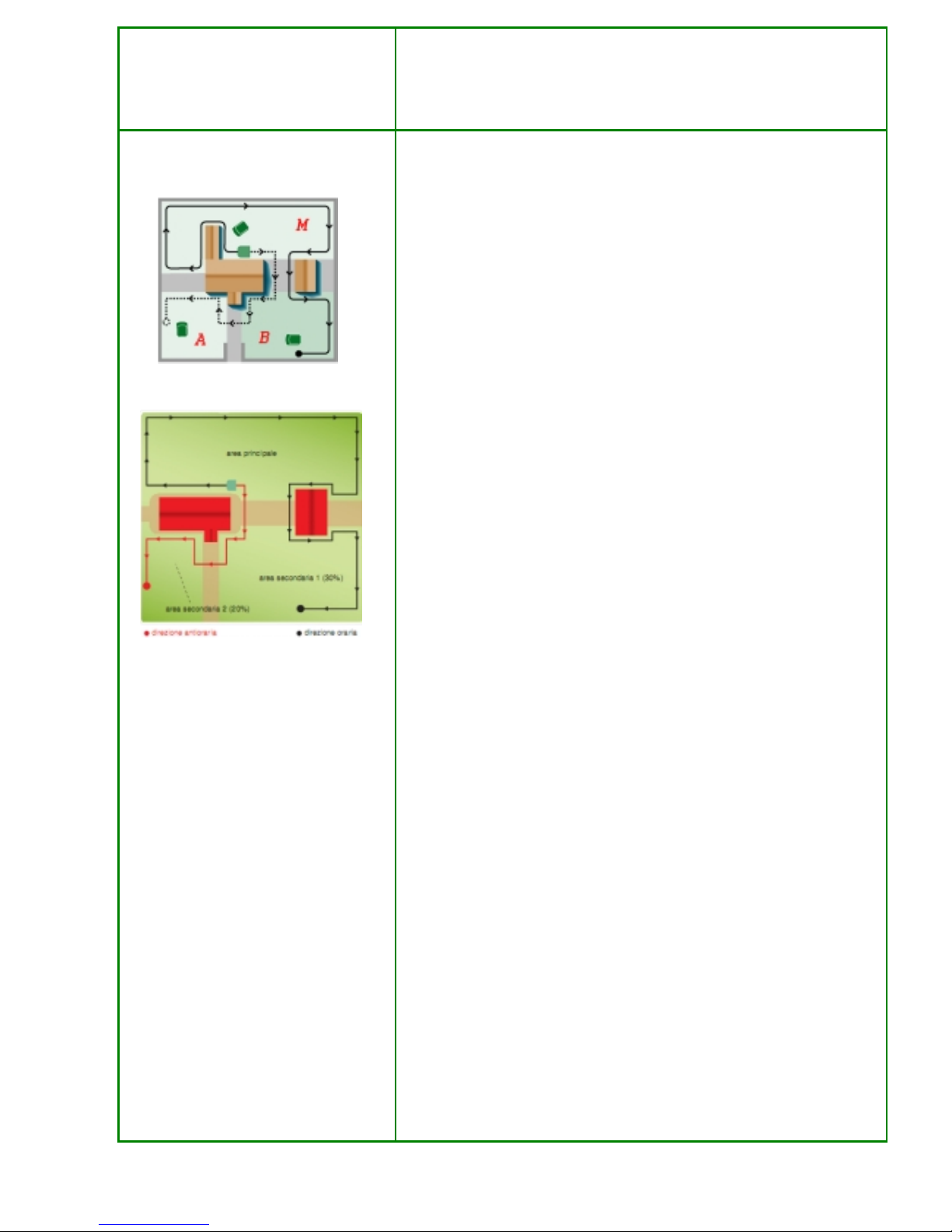
In case the primary area, where the recharging base is positioned, is smaller,
please set out the values as follows:
PA SA1 SAD1
1500 2000 60%
1000 2000 70%
500 2000 80%
In case the base is positioned in a closed and very narrow area and you need
to set out the robot for working in the secondary areas, it is possible to settle
the robot as follows:
PA SA1 SA2 SAD1 SAD2
0 2000 1000 70% 30%
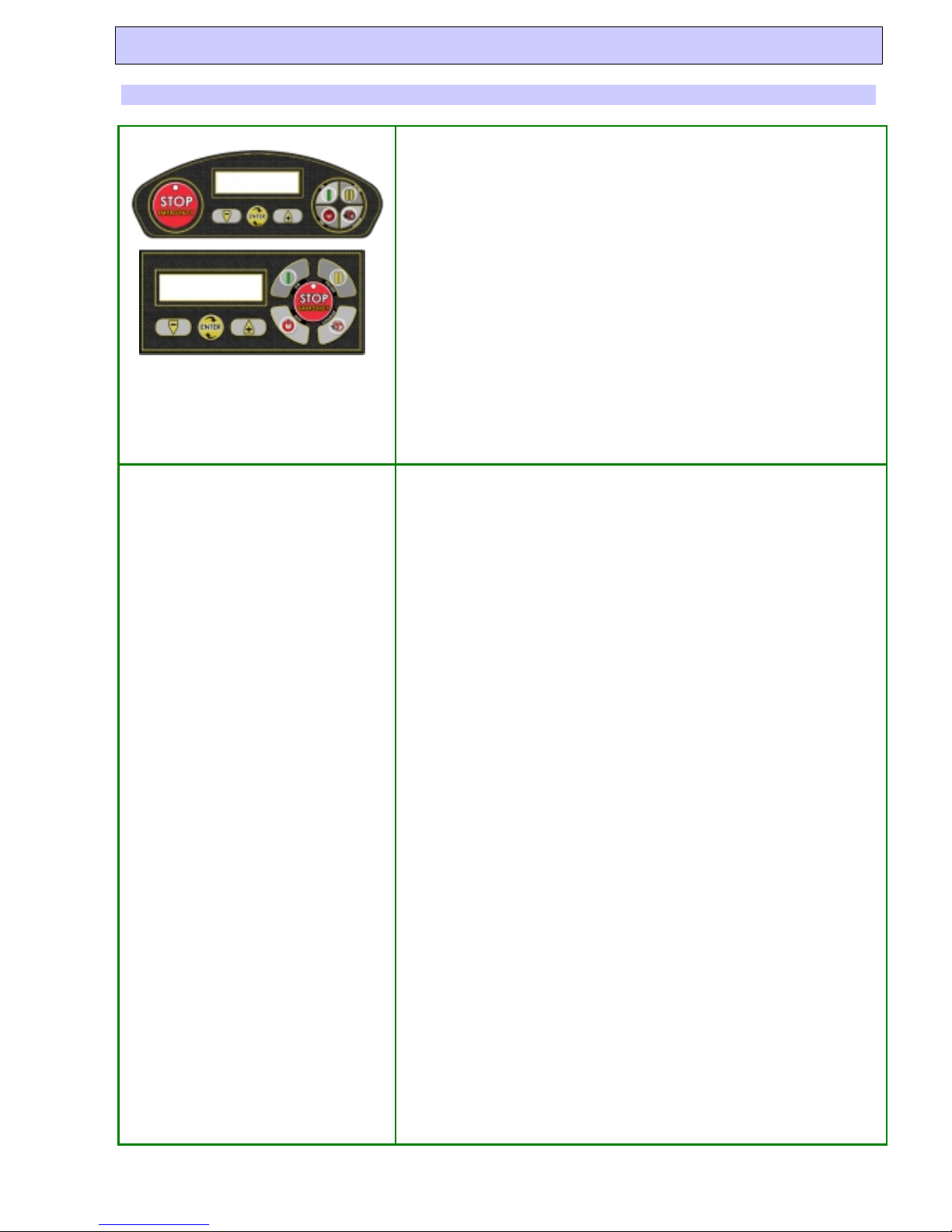
Bluetooth Software installation in mobile
phones and Control over the robot
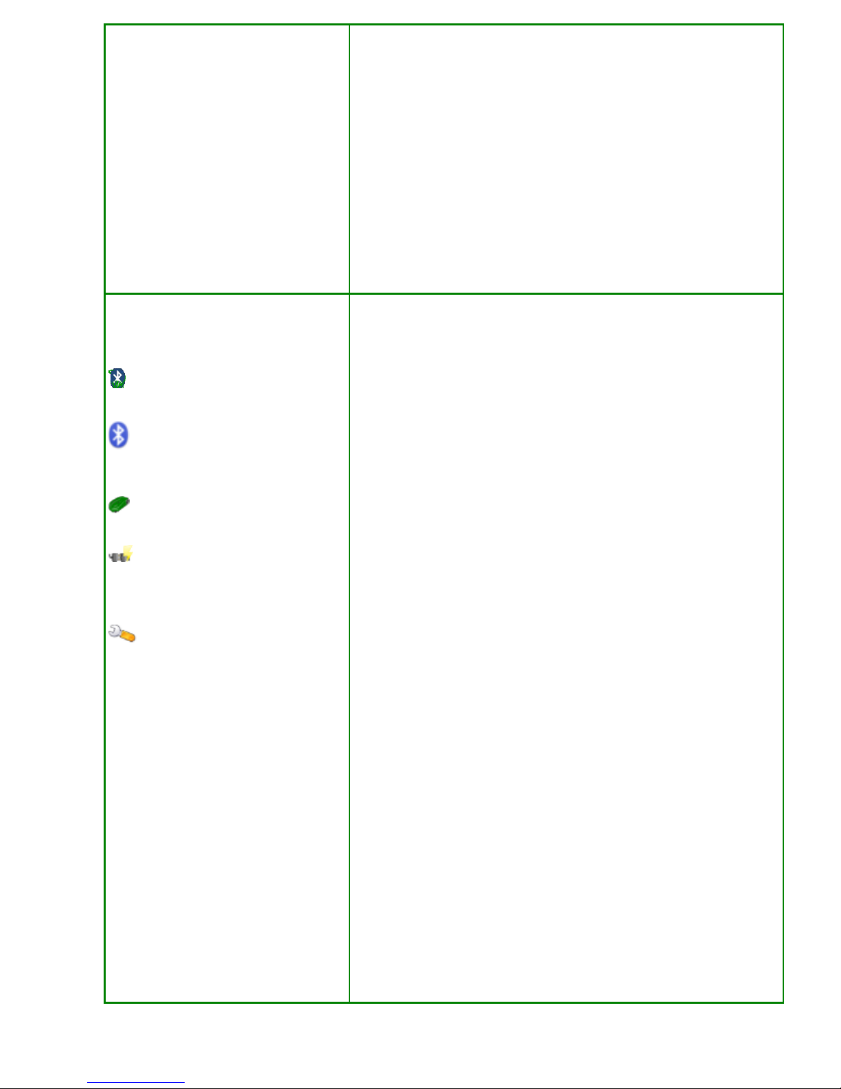
Software Icon on the mobile phone
Robot Search. Function for
activating new robots research and for
combining with them.
Quick Connection to the Robot
already previously combined.
Charge Key. It orders the robot to go
to the recharging base or, in case it is
already in the recharging base, it orders
the robot to come out.
“Configure” Key. It permits to enter
the User’s Programming.
In order to control the robot with your own mobile phone, you need first of
all to have a mobile phone supporting Bluetooth, Java and which permits the
Java applications to control the Bluetooth module. In technical terms, it is
necessary for the mobile to support this function “A midlet can use Bluetooth
(JSR-82)”. To install the software you need to have a PC with Bluetooth.
Download with “LAWN MOWER PROGRAMMER” the last release. Select
“Other”.
A folder will open: 3 short movies are available showing instructions on how
to install the software on the mobile in three different ways (according to the
Bluetooth module available on the PC).
In general the operation consists in selecting the file “BT-Remote-
Control.jar” and then select in the menu FILE->Send to->Bluetooth device.
At this point the procedure changes in relationship with the Bluetooth
module installed on the PC, but in general it consists in searching for the
mobile phone, selecting it, defining a connection password (for instance 1234)
and pressing the button “send”. Follow the instructions appearing on the
mobile. At this point the software has been installed in the mobile phone.
Each model of mobile phone has its own way for saving the received files.
Generally, they are saved in “Received Files, Applications, Collection or
Games”.
After having found and executed the received file, the first time it is
necessary to select the language and combine the phone with your robot.
• Switch the robot on and enter the User’s Menu.
• Select the option Bluetooth. Configuration.
• Select ID on which we want to set up the phone. (It is possible to set
up up to 3 handy phones enabled to drive the robot.) The connection
between robot and handy phone cannot take place contemporarily
with more than one handy phone.
• It begins to count 60 seconds down; the combining operation must
be completed within the 60 seconds, otherwise it is necessary to
repeat the operation.
• On the mobile phone, execute the application “Remote”.
• Select “Robot Search”. At the end of the research a list of the
individuated robots is displayed. Select the robot which we want to
connect to and press the OK key. Automatically the Robot have the
name of “ROBOT”.
• The Robot stops counting down and at this point the combination
has been pursued.
• Press the Pause key on the mobile to check it works properly.
• From now on, in order to connect with the Robot it is sufficient to
select in the mobile the option “fast” for a faster connection.

- 11 -
With the mobile phone, it is possible to make the following operations:
'Drive the robot in all directions. Pay attention: when the robot meets
the perimeter cable or it bumps, the robot has the priority control
over the mobile phone. Until the movement for re-entering the
perimeter has not been fulfilled, it is not possible to control the robot
with the mobile.
'Settle it in Pause and restart it.
'Settle the spiral in order to optimize the work in that area.
'While the robot is working, it is possible to send it back to the
recharging base.
'While the Robot is in the recharging base, it is possible to:
oLet it get out of the recharging base.
oSettle it in Pause modality and enter the User’s
configuration. (Working times, Secondary Areas, Rain
Sensor, Perimeter Y/N, Robot’s name etc….)

- 12 -
Upgrade and Connection – Mother Board
1. + Battery
2. – Battery
3. L300 - F3 - Fuse 30Ah
L200 - F3 - Fuse 20Ah
4. F4-Fuse 315mAh Delay
5. Recharging connectors
6. Right wheel motor
7. Left wheel motor
8. Display Connector
9. L200 - Microswitch
10.serial connector (Upgrade and
Bluetooth remote control)
11. Sinusoidal Receiver
12. Coil
13. F1-Fuse 1Ah
14. L200 – Light bulb.
15. Blade Motor
16. Anti reversing detector.
17. Display Connector.
Display Board Connection (200Z04600A)
Mother
Board
Alarm Compas
s
Rain
Sensor
Security
Handle
Mother
Board
Left Bump
Central
Bump
Right Bump
Keyboard
Board version
Dip-Switch
1-ON (Front lifting active)
2-ON (Emergency stop active )

- 13 -
Robot Software Update
Version Updating. With the new
programmer
Ambrogio Client
The new programmer doesn’t work
on Windows98 and previous.
The robot update is made with the Programming Software which can be
downloaded from Cassiopea.
There are two different Update procedures: The manual and the automatic one.
Before speaking about the update procedure it is necessary to know that the
mother boards Version Advanced Mode V. 2010 contain a part of the code inside
the software, which allows the robot to recognise the model automatically. By this
mode it is also possible to update the microprocessor with a protocol of ours. This
software portion is called BootLoader. In case the mother board looses the
programme because of any reason, it is necessary to install the programme again,
not with the standard software but only with the Boot Loader. Only after this
action it is possible to install the new programme in the mother board with the
software version without using the auto recognition.
The function “Guided Update” allows us to update the robot through the auto
recognition (Only V. 2010) or through the manual selection of the model and the
software.
• Auto recognition. With this mode the model of the robot is recognised and
the software suggests the available updates. Normally only the update of
the motherboard or of the whole robot is available.
• No Auto recognition. With this mode it is necessary to select the model
manually. Step by step the software will suggest the devices which can be
updated
The function “Advanced Update” is available only for expert users and it allows
us to choose the kind of microprocessor and the version to be updated. It is a low
level function which can make the device unusable in case it is used in an incorrect
way.
The updated mother boards of the last generation, as they are switched on, show
some information needed to understand the state of the art of the software and
hardware.
On the display it is shown as follows
Robot L2E A 09
V. 2009/12/04
Robot L2E-> It indicates the model of Robot .
A-> It identifies the mother board advanced mode V. 2010
09-> It indicates the mother board revision
V. 2009/12/04 -> The version date which is then replaced by the internal code of
the release, for instance (r.5814)
When we start the software we check the compatibility with the software of the
boards : Display, Alarm, Compass and Sinus receiver. In case the software of
these boards is not compatible with the same version of the mother board, the
motherboard shows an error such as the following one:
DISPLAY R 5810
Required R 5814
This message means that in the display there is the release 5810 which is not the
last version and so there could be problems with the functioning of the robot. We
suggest to you to update the display board. With the key ENTER it is possible to
ignore the message and to go on. The possible messages are the following ones:
DISPLAY, ALARM, COMPASS, RECEIVER.

- 14 -
Here below you can find the procedure to set up and to use the programmer :
It is necessary to configure the serial connected to the Robot only the first time.
1. Select File-Set up
2. Select the serial port
Update Procedure
1. Select guided File Update
2. In the models with advanced mode we must leave the
auto recognition activated
N.B. Disabled for the models of previous version
3. Auto recognition successfully completed.
Press the key “Next”
4. The programmer suggests the possible updates for this
model.
●Full Update Total update of all the electronic devices.
Suggested procedure.
• Update boot loader.. It resets the boot Software needed to
update the new boards. After updating a board with the
boot loader it is necessary to update the board with the
Manual procedure..
• Update Motherboard Only.Update of the only mother
board.

- 15 -
5. With the option “Forced Update” disabled. The software
updates the motherboard and the peripheral devices only
if it is necessary.
6. Once the update has been completed the update situation
of each electronic board is shown. In this case the boards
had already been updated and the board of the compass
was not present.
7. Example for the update by activating the flag “Forced
Update”. The Software forces the update even if it is not
necessary. In case there are problems with the update of a
board the error message is shown.

- 16 -
Service Menu
Service Menu - (Release November 2009)
Only retailers and authorized technicians can enter the Service menu. There are some submenus. All the indications are in
English only
1. “Statistics”: Used to verify the health state of the machine. It informs about working hours, errors occurred and
state of batteries.
2. “Test Motors”:Used to verify the wheel and cutting motors functioning.
3. “Battery Type”: Used to change the type of lithium batteries.
4. “Test Signal”: Used to execute more accurate controls on the signal values.
5. “Test Tilt”: Used to control the inclinometer functioning.
6. “Test Bump”. Used to check the correct functioning of each bump sensor.
7. “Safety Handle”. Enable or disable the handle control.
8. “Safety Lift”. Enable or disable the control on the lifting cover. ACCORDING TO MODELS.
9. “Compass”. Used to enable or disable the Compass use. ACCORDING TO MODELS.
10. “Blackout”: Used to deactivate the attempt of signal recovering, when the robot looses the synchronization. In
case of swimming-pools nearby we advice you to put this option on “STOP”.
11. “Border Blade”: It permits to turn off the cutting blade, while following the wire. “ACTIVATE ONLY
ACCORDING TO ZCS ADVICE”
12. “Hot Blade”: It allows us to control the temperature of the cutting motor. If the value is over the limit established
by the manufacturer, the robot switches the blade off, by continuing its movement waiting for the temperature to
lower again so that it can restart the blade. “ACTIVATE IT ONLY ACCORDING TO ZCS ADVICE”
13. “Force charge”: During the entrance in the recharging base, it imposes the power supply to speed up the
recharging. “ACTIVATE ONLY ACCORDING TO ZCS ADVICE”
14. “Debug”: Used to visualize some useful information to detect problems in place of battery signalling while the
robot is operating.
To enter the menu, push in sequence the keys: ON, PAUSE, CHARGE, Key (+) and Key (-).
Scroll the key (+ or - ), and select with ENTER
Service menu parameters must be changed only by high qualified staff. Here below a short legend of main
parameters:
Default Advices
Battery Type Pay attention to the stick on battery. You cannot install batteries of different
type on the same machine.
Safety Handle ON Disable only for debug in agreement with client to verify if the switch-off of
the blade is caused by the handle safety system.
Safety Lift OFF If enabled, it controls the cover lift through a sensor positioned on it.
SENSOR NOT AVAILABLE.
Compass OFF To enable only if the Compass is present
Blackout RESTART Set it on “STOP” but only in presence of swimming pools. If the robot looses
signal, it doesn’t attempt the recovering but it stops and displays “SIG 04”..
Hot Blade ON By setting this parameter on “OFF” it doesn’t control the temperature of the
cutting motor. You must set it on OFF only according to Zucchetti Centro
Sistemi Advice.
Border Lenght Standard Set on “Long” only if robot has not enough autonomy to go back to the
recharging base. ATTENTION !!! Robot work autonomy is reduced by at
least 30 minutes.
Force Charge OFF During the entrance in the recharging base, it imposes the power supply to
speed up the recharging.
Set it on ON, only if recommended by Zucchetti Centro Sistemi technicians.
Debug Battery ON
Temperat. OFF
Handle Val OFF
Ampere Val. OFF
Free Stack OFF
We can change it only according to Zucchetti Centro Sistemi Advice.
Temperature. Cutting Motor Temperature
Handle Val. Handle Safety Values
Ampere. Wheel Motor Current
Free Stack. Reserved to the engineers Zucchetti Centro Sistemi

- 17 -
Service Menu: “Statistics”
This menu allows you to check the robot conditions. Here you can find info about working time, errors and batteries.
The following info is displayed:
First Charge date of the first charge.
Charge Number of charges done.
Charge Time time necessary to charge the batteries. The lower the time is, the more used are those
batteries. If this value reaches 30 minutes, batteries must be replaced.
Total Work Time total robot working time.
Last Work Time working time of the last working cycle.
Failed Charge number of failed charges caused by an abrupt contact loss in the recharging plates or for a
contact loss in a post step. Any crashes are not considered as causes for a failed charge.
Clock Error Errors occurred in the clock. Ask the manufacturer.
Blackout (DATE) X/Y/Z. Show the date from last time signal error occurred. The important parameter
indicating blackout number is the last value.
Checksum Error It shows the date of the last time in which the Robot gave checksum error. In case the robot
shows this error it is necessary for us to set up the whole user menu and the service menu.
We must also inform Zucchetti Centro Sistemi about this inconvenient.
Temperature MAX It shows the maximum temperature reached by the cutting motor after the last “Clear Error”.
The temperature is important to understand possible faults in case the motor is internally
burnt.
Low Battery last time the robot switched off for low battery and total number of the times an error has
been indicated. Generally the problem is caused by problems on the way or on the base
which do not allow the robot to recharge.
High Battery last time the robot switched off for high battery and total number of the times an error has
been indicated.
Out of Border last time the robot stopped for an out-of-perimeter and total number of the times an error has
been indicated.
Blocked last time the robot blocked and total number of the times an error has been indicated.
E01-Right Motor last time the robot stopped for ‘Motor Error’ and total number of the times an error has been
indicated.
E02-Left Motor last time the robot stopped for ‘Motor Error’ and total number of the times an error has been
indicated.
E03-Blade last time the robot stopped for ‘Blade Motor Error’ and total number of the times an error has
been indicated.
Last clear Error Show the date of the ast setting at zero in statistics.
Clear Errors it clears all the errors shown in the Statistics till now. Check every single error before
clearing.
Service Menu: “Test Motors”
This menu allows you to check more thoroughly the motors operation. With the ENTER key the
cutting motor switches on and off. With the (+) and (-) keys you can start up the wheel motors
increasing the speed up to 100%.
LF”; Left Motor Speed BL”; Cutting Motor Speed “RG”; Right Motor Speed
With charged battery and with the robot with raised wheels we push the wheel motors up to 100%. The
blade is switched on. In this case the ideal values are the following ones:
“LF>=40” “BL>=40” “RG>=40”. The speed already shown by the robot shows for the cutting motor the
turns x100 40=4000rpm, rather than for the wheel motors they are the turns per minute of the external
wheel.
During the modulation the turns of the blade motor decrease up to about 29-30.

- 18 -
- Different values indicate failure problems, errors with the encoder (pulse control card) or
broken “F1” fuse in the Mother Board
Should the wheel motors register a high current absorption, the wheel motor speed will be
brought back to 0% in few seconds.
Service Menu “Battery Type”
This menu is used to set the type of battery present in the robot. In case of battery change, set the right
parameter.
DO NOT INSTALL DIFFERENT TYPES OF BATTERIES IN THE SAME ROBOT.
In order to verify the correct type of battery is installed, it is necessary to check if
one of the following values is displayed:
In case of Lithium Type “A” it is displayed: Battery 2750 A.
In case of Lithium Type “B” it is displayed: Battery 2750 B.
Service Menu “Test Tilt”
This menu allows to check the right working of the inclinometer. If the sensor does not work
properly, the blade is not activated and then the display shows the “Tilt error” message.
The display shows the “Pitch” and “Roll” values in degrees that refer to the inclination of the two
axes of the robot compared to the horizontal plan. Every time the robot goes into the recharging
base, it resets the reference of the two terrestrial axes of the sensor. The horizontal plan of the
robot will be the new reference parameter. When the values are being checked, it is necessary
to place the robot in a horizontal plan without lifting the wheels. The parameters must be near 0
of a few units. The ENTER key allows the reset and zeroing the values.
Service Menu “Test Bump”
This menu allows you to check the bump sensor is properly working.
Once entered the submenu, 3 values appear. The first value indicates the left bump sensor. The
second one indicates the central bump sensor and the third one is the bump sensor on the left.
Every time the sensor is activated, the counter increases. On the robots equipped with
mechanical bump detectors only one value is shown, referred to both the microswitches.
Service Menu “Blackout”
This menu allows to set the robot functioning when it loses the signal synchronism.
“STOP”. Once the signal is lost, the robot stops displaying “Blackout – SIG04”
“RESTART”. Once the signal is lost, the robot tries to recover it. If when turning on itself, it does
not find any bump or wire, it starts working regularly. Otherwise it stops for safety reason.
In case of swimming-pools inside or adjacent the installations, we advice to set the parameter on
“STOP”

- 19 -
Service Menu “Border Blade”
This option allows you to switch off the cutting disc during the wire following. It can be helpful
whenever there are strong signal disturbs and the robot can not find the perimeter wire while
looking for the charger.
- OFF- it disables the cutting disc
- ON- it enables the cutting disc (default setting up).

- 20 -
Errors displayed by the robot and related causes
Errors list
BUS Error
The Bus Error shows a communication problem between the motherboard
and the peripheral devices. The problem can occur as follows:
• During the working time, the robot displays the message for 1 sec.
then it disappears immediately and the robot keeps working. In this
case, it is only a warning and you should do nothing.
• Robot just switched on. In this case, it means a faulty peripheral
device is giving problems to the 12V of the motherboard. The first
thing to do is to check the fuse F1, then to identify the faulty device, it
is necessary to detach every single part (motors, sinusoidal receiver,
Bluetooth, compass and alarm).
oTry to switch on the robot. If the problem persists, it means
the motherboard or the display card is damaged.
oConnect a peripheral device at a time, trying each time to
switch on the robot and check the problem.
• As soon as the robot gets out of the base, the communication with the
display starts. If the problem occurs now, maybe there is a bad flat
connection between motherboard and display, or maybe the display
or the motherboard is broken.
• Occasionally. During the working time, the
robot stops displaying “BUS ERROR”. In this case, the best thing is
to test the robot detaching the compass flat and the alarm, in order to
check if the problem is with one of the two peripheral devices.
“Blackout”
“Problems in detecting the signal”
“Not regular Robot movements such as, for
example, moving forward for 1 meter,
coming back, moving again forward, again
backwards”
In the statistics menu there are three different values which point out how
serious is the problem. The most serious is the third one, which tells you how
many times the robot stopped with this error.
Robot can stops working for 4 different reasons:
• SIG01: Robot loses signal while following a straight line of wire;
when the signal got back robot, it did not find the wire on the left
and it stopped for safety reason.
• SIG02 : Robot lost the signal while it meets the wire on curve and it
stops for safety reason.
• SIG03 : Robot lost the signal during normal working; when signal
got back, the robot was next to wire and stopped working for safety
reason.
• SIG04 : Robot lost the signal without trying to recover it, gave the
error message because in the service menu the parameter “Blackout”
is set on STOP
Possible reasons:
- The power supplier goes under protection during the hottest hours.
Should that be the case, space the transmitter and install the charger
and the transmitter in an aired seat.
- Flowerbeds not correctly made (clockwise). You can easily find out
the error because the problem usually occurs next to the flowerbeds
and the robot does not recognize its wire about 30cm before.
- Excessive perimeter cable length (see the explanation under the
transmitter) . You can solve this problem, by installing the signal
amplifier.
- Damaged perimeter wire, which is going to break. Check the Ohm
and the impedance with a tester, as shown in the section “Looking
for the perimeter wire interruption”.
- Coil inside the robot, which is come off. Disassemble the front part
and check.
- Especially in case of not regular movements, the cause is a signal
attenuation. It is im
p
ortant to check the
p
erimeter cable
,
estimate if
This manual suits for next models
1
Table of contents
Other Caiman Lawn Mower manuals