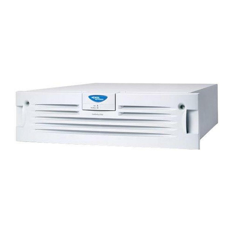
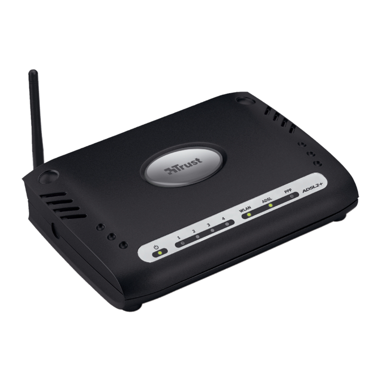
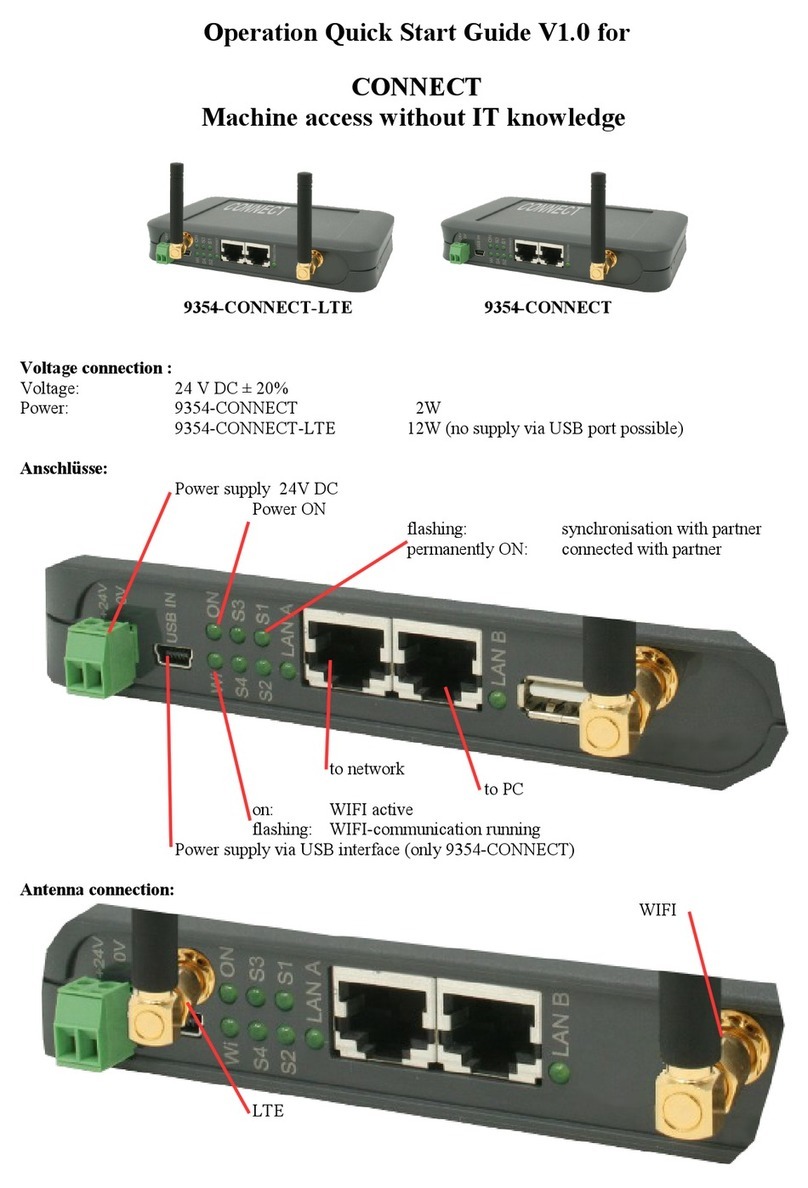
Meteo Control SFCE 4GWiFi-11 User manual

meteocontrol | Suite 1203, Level 12, Tower 2, 475 Victoria Avenue | Chatswood 2067, NSW | Australia | phone (02) 8188
Contents
1. Hardware Installation...................................................................................................................... 4
1.1 Physical Structure......................................................................................................................... 4
1.2 LED Status.................................................................................................................................. 6
1.3 Router Dimensions ..................................................................................................................7
1.4 Installation ..................................................................................................................................7
1.4.1 SIM/UIM card installation..................................................................................................7
1.4.2 Ethernet cable connection (LAN Port)......................................................................... 8
1.4.3 Power supply........................................................................................................................ 8
1.4.4 Antennas................................................................................................................................ 8
1.5 Network Quality Assessment.............................................................................................. 11
2. Router Configuration..........................................................................................................................12
2.1 Router Firmware.....................................................................................................................12
2.2 Router Standard Modes (Internet Connection)............................................................13
2.3 Router Backup Modes (Internet Connection)...............................................................16
2.4 Computer Connection.........................................................................................................20
2.5 Cellular Network Configuration........................................................................................24
2.6 Dual LAN port configuration.............................................................................................27
2.7 WLAN Communication–Access Point (AP) Configuration......................................28
2.8 WLAN Communication –Wireless Client Configuration..........................................30
2.9 Router Backup Mode Configuration...............................................................................33
2.10 ICMP Check Configuration.................................................................................................35
2.11 Router M2M Platform Registration Configuration.....................................................36
2.12 Scheduled Reboot Configuration ....................................................................................38
2.13 Firmware Upgrade................................................................................................................44

meteocontrol | Suite 1203, Level 12, Tower 2, 475 Victoria Avenue | Chatswood 2067, NSW | Australia | phone (02) 8188
2.14 SMS Reboot Configuration................................................................................................44
Tables
Table 1: Router port description ........................................................................................................... 5
Table 2: Router LED status description............................................................................................... 6
Table 3: CSQ Condition Reference ................................................Error! Bookmark not defined.
Figures
Figure 1: Router physical structure....................................................................................................... 5
Figure 2: 3GWiFi-11 router dimensions................................................................................................7
Figure 3. 3G/4G WIFI-11 Router Sim Card Installation................................................................... 8
Figure 4: Antenna setup procedure..................................................................................................... 9
Figure 5: Network coverage map - www.opensignal.com..........................................................12
Figure 6: Cellular connection plan ......................................................................................................14
Figure 7: Wireless client connection plan.........................................................................................15
Figure 8: WAN connection plan...........................................................................................................16
Figure 9: Cellular Preferred, WAN Backup Plan.............................................................................17
Figure 10: Cellular Preferred, WLAN Backup Plan..........................................................................19
Figure 11: WAN Preferred, Cellular Backup Plan.............................................................................19
Figure 12: Network Connection Step 1...............................................................................................21
Figure 13: Network Connection Step 2.............................................................................................22
Figure 14: User identify page...............................................................................................................23
Figure 15: Router Status.........................................................................................................................23
Figure 16: Cellular network setting page..........................................................................................25
Figure 21: M2M Settings........................................................................................................................37

meteocontrol | Suite 1203, Level 12, Tower 2, 475 Victoria Avenue | Chatswood 2067, NSW | Australia | phone (02) 8188
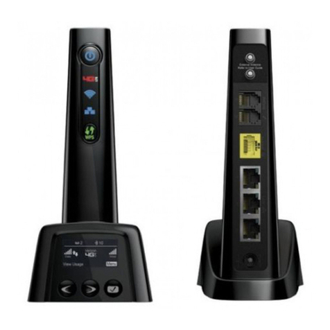
Front
Back
Figure 1: Router physical structure
Table 1: Router port description
Port
Description
USIM
Plug type SIM Slot, support 1.8/3V/5V automatic detection
3G/4G
3G/4G antenna, SMA connector, 50Ω
Aux/WiFi
Wi-Fi antenna, SMA connector, 50Ω
LAN
Ethernet downlink service interface, 10/100Base-TX, MDI/MDIX self-
adaption, connect Ethernet port of computer or switchboard, concentrator
WAN/CON
Ethernet uplink service interface,10/100Base-TX, MDI/MDIX self-adaption,
connect switchboard or Router. CON for debug test
RST
Reset button
PWR
Power connector
Aux/WiFi
WLAN
WA
N
LA
N
NET
WAN/CO
N
RST
PW
R
LAN
USIM
3G/4G

meteocontrol | Suite 1203, Level 12, Tower 2, 475 Victoria Avenue | Chatswood 2067, NSW | Australia | phone (02) 8188
1.2 LED Status
Table 2: Router LED status description
LED Tag
Colour
Status
Description
NET
Green
Solid Light
Signal is strong. Normal router and SIM operation
Yellow
Solid Light
Adequate 3G/4G signal strength. Normal router and SIM
operation
Red
Solid Light
Weak 3G/4G signal. Normal router and SIM operation
Slow
Flashing (2 s
intervals)
Already logged in network or dialling online
Quick
Flashing (0.5
s intervals)
Dialling
WLAN
Green
Solid Light
WLAN port is enabled but no data transmission
Quick
Flashing
Data transmission
Off
WLAN port disabled
LAN
Green
Solid Light
LAN port connected
Flashing
Data transmission
Off
LAN port not connected
WAN
Green
Flashing
Link to Ethernet device established. No data transmission
Quick
Flashing
Data transmission
Off
No link to Ethernet device

meteocontrol | Suite 1203, Level 12, Tower 2, 475 Victoria Avenue | Chatswood 2067, NSW | Australia | phone (02) 8188
1.3 Router Dimensions
Figure 2: 3GWiFi-11 router dimensions
1.4 Installation
1.4.1 SIM/UIM card installation
Remove screw on the side of the router to open the SIM card cover, and insert the
SIM/UIM card
WARNING
Before installing the SIM/UIM card, please disconnect any power
resource of router.
Please insert the SIM card correctly by following the illustrated Sim profile as shown at
the bottom of the SIM Slot
73.5 mm
24.6 mm

meteocontrol | Suite 1203, Level 12, Tower 2, 475 Victoria Avenue | Chatswood 2067, NSW | Australia | phone (02) 8188
Figure 3. 3G/4G WIFI-11 Router Sim Card Installation
Reinstall the SIM card cover in order to protect the SIM card during router operation
1.4.2 Ethernet cable connection (LAN Port)
LAN Port: Use Ethernet cable to connect the 3G/4GWiFi-11 Router to downlink devices,
i.e. computer, data concentrator,switch, etc
WAN Port: Use Ethernet cable to connect the 3G/4GWiFi-11 to uplink devices, i.e. ADSL
router, etc
1.4.3 Power supply
Connect the 3G/4GWiFi-11 routers to a proper DC Power Supply. In order to get high
reliability, the 3G/4GWiFi-11 router adapts to a wide voltage inputRange i.e. +5V~
+26VDC, support hot plug and complex application environment. The equipped router
power supply is rated at 12V 1.5A DC.
1.4.4 Antennas
Connect the 3G/4G antenna to the 3G/4G SMA connector on the router (Figure 1);
similarly connect the WiFi antenna to the Aux/WiFi SMA connector. The antennas are
Omni-directional; therefore it is imperative that it is mounted upright. See below for
router Antenna installation guidelines

meteocontrol | Suite 1203, Level 12, Tower 2, 475 Victoria Avenue | Chatswood 2067, NSW | Australia | phone (02) 8188
The high gain (10 dBi) antenna comes with 3 sections. Follow the below steps to setup
the antenna:
Figure 4: Antenna setup procedure
1
2
1. Antenna base
2. Antenna lower
section
3. Antenna upper section
1. Screw on the lower
antenna section to the
antenna base.
2. Place the upper
antenna section onto
the lower antenna
section.
Ensure the screw lines
up with the flat surface
of the lower section
.
3. Screw and tighten the
upper antenna section

meteocontrol | Suite 1203, Level 12, Tower 2, 475 Victoria Avenue | Chatswood 2067, NSW | Australia | phone (02) 8188
ATTENTION
Please connect the antenna before energizing the router to avoid impedance
mismatching which may result in poor signal.
Make sure that the right antenna is connected to the right SMA connector. Wrong
connection may result in poor signal.
Ensure that the magnetic-base antenna is mounted upright on a metal surface and
outside an enclosure, clear from obstructions for maximum performance, see below for
reference. A metal surface acts as a ground plane for the antenna, which acts as the
second half of the antenna. The larger the metal surface the better the performance.
The Antenna must always be mounted upright unless certain situations where the
Antenna is located in a basement, it can be adjusted to horizontal to achieve a better
signal.
3
4
6
Hex Key

meteocontrol | Suite 1203, Level 12, Tower 2, 475 Victoria Avenue | Chatswood 2067, NSW | Australia | phone (02) 8188
1.5 Network Quality Assessment
Determine whether 3G or 4G is more prevalent at your site by checking on
www.opensignal.com.
1. Enter the address
2. Select cellular type
3. Select provider
The map will generate blocks that scale in colour where green is good and red is poor
signal strength. This is a useful tool to quickly check whether there your site has
3G/4G Antenna
mounted upright on
metal surface
3G/4G Antenna
mounted upright on
non-metal surface
3G/4G Antenna is
horizontal
WiFi antenna is mounted upright
WiFi antenna is mounted horizontally

meteocontrol | Suite 1203, Level 12, Tower 2, 475 Victoria Avenue | Chatswood 2067, NSW | Australia | phone (02) 8188
adequate signal for the router. If poor signal is experienced onsite after checking
coverage maps, please contact technical support and you may have to install a
directional antenna to improve the signal strength.
NOTE: This is a recommended open source tool used as an indicator and we do not
guarantee this to reflect the signal quality experienced on site. For most accurate
measurement we suggest bringing both the 3G and 4G router to site to check which
network is available.
Figure 5: Network coverage map - www.opensignal.com
2. Router Configuration
2.1 Router Firmware
1
2
3
8

meteocontrol | Suite 1203, Level 12, Tower 2, 475 Victoria Avenue | Chatswood 2067, NSW | Australia | phone (02) 8188
The 4G SFCE Wireless Router can be configured to either of the following modes with
the different Model Name
Standard Modes: Model 4GWiFi-12
Main Features:
(1) Support Dual LAN Port Configuration
(2) Multi SSIDs function for enabling “Access Point” & “Wireless Client”
Backup Modes: Model 4GWiFi-11
Main Features:
(1) Internet Backup mode Configuration
Prior to set-up the router for the required configuration, please confirm the model
number/Internet Support Modes in order to install the correct firmware to the router.
The Standard Modes internet connection and the Backup Modes connections are
illustrated and explained in the following sections.
2.2 Router Standard Modes (Internet Connection)
There are three ways that this router can receive internet in the Standard Mode. This
section points out the relevant sections for each setup. It is recommended to start from
section 2.2 before jumping to other sections.
1. Cellular connection (see Section 2.5 for configuration details)

meteocontrol | Suite 1203, Level 12, Tower 2, 475 Victoria Avenue | Chatswood 2067, NSW | Australia | phone (02) 8188
Figure 8: WAN connection plan
2.3 Router Backup Modes (Internet Connection)
The above internet connection options for Standard Modes could be also used as
backup purposes. Backup mode ensures a redundant connection by falling back to
another internet connection. For example, Cellular preferred, WAN backup means that it
will prioritise a cellular over a WAN connection when there is a cellular connection. This
option is possible when there is a WAN connection on site.
The 3G/4GWiFi-11 routers can be configured to use the following back-up mode
options to allow internet accessibility to become more robust:

meteocontrol | Suite 1203, Level 12, Tower 2, 475 Victoria Avenue | Chatswood 2067, NSW | Australia | phone (02) 8188
3. WAN Preferred, Cellular Backup (See Section 2.5 & 2.9 for configuration details)
Figure 11: WAN Preferred, Cellular Backup Plan
IMPORTANT NOTE:
Figure 10: Cellular Preferred, WLAN Backup Plan

meteocontrol | Suite 1203, Level 12, Tower 2, 475 Victoria Avenue | Chatswood 2067, NSW | Australia | phone (02) 8188
(1) When the WAN/CON port is required to be converted to a LAN port, this option is
only applicable for Standard mode - the back-up mode does not support this
function.
(2) When the 3G/4GWiFi-11 Router is on “Cellular Preferred, WLAN Backup” mode, the
AP (Access Point) will become disabled.
2.4 Computer Connection
In order to configure the router, it needs to be connected to a computer via a direct
connection or wireless connection.
To establish the connection, the IP address can be either set as static or DHCP. The
default IP address and subnet mask of the router are 192.168.1.1 and 255.255.255.0,
respectively.
The IP settings on the computer can be set as follows:
1. Click “start > control panel”, double click on “Network and Sharing Center” icon
then select “Local Area Connection”. Double click on the “Properties” icon, select
“Internet Protocol Version 4 (TCP/IPv4) then double click “Properties”
10
This manual suits for next models
1
Table of contents


