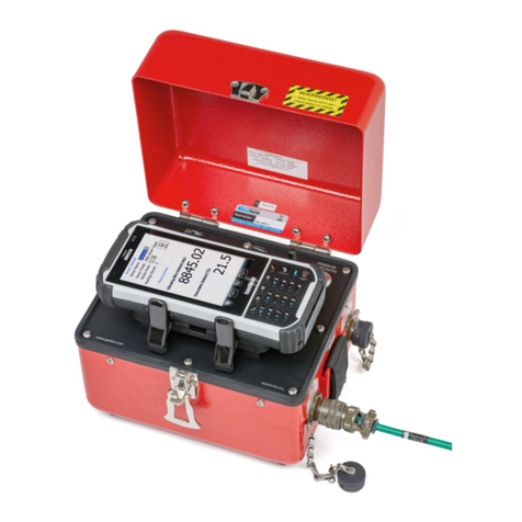
MetLogix Mx Series User manual

2
Digital Readout
User’s Guide
Mx100 Digital Readout Software User’s Guide
Published by:
Metlogix Incorporated
175 Canal Street Suite 503
Manchester, NH 03101 USA
Telephone 603.836.4452
Facsimile 603.369.6499
info@metlogix.com
www.metlogix.com
User’s Guide part number: 16100-00
Publishing date: October 29,2019
Printed in United States of America
Copyright © 2019 by Metlogix, Incorporated, Manchester, New Hampshire
Mx-100 software version: 1.00.00
All information set forth in this document, all rights to such information, any and all inventions disclosed herein and any patents that
might be granted by employing the materials, methods, techniques or apparatus described herein are the exclusive property of
Metlogix, Incorporated., Manchester, New Hampshire.
Terms, conditions and features referenced in this document are subject to change without notice.
No part of this document may be reproduced, stored in a retrieval system, or transmitted in any form or by any means, electronic,
mechanical, photocopying, recording, or otherwise, without prior written permission of Metlogix, Inc. Requests to Metlogix, Inc. for
permission should be addressed to the Customer Services Department, Metlogix, Incorporated, 175 Canal Street, Manchester, New
Hampshire 03101.
Limit of liability and disclaimer of warranty
While this guide was prepared with great care, Metlogix makes no representations or warranties with respect to the accuracy or
completeness of the contents of this book and specifically disclaims any implied warranties of merchantability or fitness for a particular
purpose. The advice, methods and instructions contained in this book might not be suitable for your situation. When in doubt
regarding suitability, you are encouraged to consult with a professional where appropriate. Metlogix shall not be liable for any loss of
profit or any damages, including but not limited to special, incidental, consequential or other damages.
Trademarks
Metlogix, is a registered trademark of Metlogix, Incorporated.
Android is a registered trademark of the Google Corporation in the United States and other countries.

3
1Introduction
The Mx100 user guide describes the operation of the Mx100 readout. The Mx100 supports manual part positioning and
encoder displacement feedback from a preset or zero position. While this guide might include some material that
doesn’t apply to your specific Mx100 configuration, the concepts explained are applicable to all Mx100 systems. For
example, Mx100 systems can be 2 or 3 axis systems with X, Y, Z or X, Y axes, however some screens in this document will
display one or the other.
1.1 Mx100 Readout
The Mx100 is a metrology readout for applications where precise machine travel in the X, Y, or Z axis needs to be
assessed. The Mx100 can be used with optical comparators, measuring microscopes and a variety of other crosshair
measurement systems where accurate encoder displacement must be maintained. All user interaction with the software
is through the color touchscreen or through the use of softkeys and function keys on the rubberized keypad.
Current encoder position can be assessed from a pre-established zero position or by pre-setting the position of an axis to
a specific value. X, Y and Z positions can be displayed in Inch or Millimeter units. A Q axis display is also available for
Rotary Encoder position output and can be displayed in Decimal Degrees(DD) or in Degrees Minutes Seconds(DMS)
format.
1.2 Prerequisites
Operators are assumed to understand the basics of dimensional metrology.
1.3 Getting Help
Help is available:
•In this guide.
•In the electronic version of this guide accessed from the Help function(“?” Button) in the Mx100 Setup Menu
toolbar.
•From your MetLogix distributor or system provider.
•From our product support page at www.metlogix.com.
If it becomes necessary to contact your MetLogix distributor or system provider, be prepared to supply the following
information:
•The Mx100 software version number and serial number. These can be read from the main Setup--> “About” page in
the Mx100 software.
•Information describing the system hardware.
•A detailed description of the problem and the steps that you’ve already attempted to resolve it.

4
User Guide Contents
This user guide is divided into 8 sections:
•The User Interface
•Zeroing and Presetting the DRO
•Sending Data via RS232
•User Setup

5
2User Interface
The Mx100 Software interface consists of a current position readout, function buttons, and toolbars for performing all
zeroing and pre-setting commands, all via a color touchscreen or keypad.
2.1 Screens
Primary screens of the software interface are:
•DRO Current Position screen(Home screen)
•Preset Position screen
•Send Result screen(RS232)
•Setup screens
DRO Current Position Screen contents include:
Current Encoder Position display
Top Toolbar
Bottom Toolbar(softkey functions)
2.2 Touch Screen – Or not!
The Mx-100 features a color touchscreen that can be used to interact with the device. For caustic or harsh operating
environments, the touch screen can be locked out and the readout can then be operated entirely by the soft keys and
function keys of the rubberized keypad.

6
2.3 The Interface Roadmap
Keys Function
Number Pad Enter numeric digits, decimal points, and sign(+/-)into the current field.
Command Keys
Enter - Select data entry field or setup menu item.
Finish - Confirm selected function or setup menu item.
Cancel -
Navigate up one level from current setting menu.
Quit – Exit the current setting screen back to the top level settings screen.
Arrow Keys Navigate the settings menu screens or numeric entry field. The left and right arrows go in
a level, or out a level. The up and down arrows move the current selection up/down.
Power Key Single Press to Power On. When On, Single Press for Screen Off, Long Press for Power Off.
Soft Keys(1-6) Executes the softkey button commands/selection displayed above the key.
DRO Keys Execute X/Y/Z/Q zerroing funciton. Select functions as vertical softkeys.
Menu Button Displays or advances the Softkey Menu. Long press to enter Mx100 Setup.
System Toolbar
Softkey Function
Toolbar
Main DRO View

7
Softkey Function Toolbar – A storage tray of commonly used functions. The default configuration displays an “Mx”
button(access to Setup), an Inch/Metric Button(to toggle display units), and a Datum indicator(displaying current
coordinate system).
Softkey Function Toolbar - A storage tray for the soft key functions. See function descriptions below.
Function Button
Icon Description
IN/MM Button The IN/MM button toggles the display units between Inch
and Millimeter.
Ref Frame Button The Ref Frame button toggles the Abs/Inc datum frame.
Send Button The Send button initiates the RS232 send function.
Cart/Polar Button The Cart/Polar button toggles the positional display format
between Cartesian and Polar coordinates.
DMS/DD Button The DMS/DD button toggles between Degrees Minutes
Seconds and Decimal Degrees mode.
Help Button The Help button provide access to the PDF User Guide. This
button can only be added to the bottom toolbar.
Setup Button The Setup button navigates to the Mx100 setup screen.

8
3Zeroing and Presetting
Creating a “Datum”, or zero position can an essential part of coordinate metrology. In many cases an inspection routine
with the Mx100 requires that the current position on the DRO is set to zero, or to some other position.
3.1 Zeroing and Presetting the Stage Position
The stage position can be zeroed or preset to a value as the reference for a measurement.
To zero a stage position:
•Step 1: Move the stage to the desired measurement reference position.
•Step 2: Press the DRO Zeroing Button(screen or keypad) to zero the stage position for the desired axes.
3.2 Presetting the Stage Position to Specific Coordinates
To preset a stage position:
•Step 1: Move the stage to the desired measurement reference position.
•Step 2: Long-press any DRO Zeroing Button(screen or keypad) to access the preset screen.
•Step 3: Enter the desired preset value for each axis and press “Finish” to complete the preset.

9
3.3 Using Two Zero Positions
•Step 1: Zero or preset a stage position that you wish to establish as your initial zero position or preset.
•Step 2: Press the datum icon( )in the upper tool bar. The datum indicator will now display ‘2’.
•Step 3: Position the stage at a new position and set your secondary zero or preset position.
•Step 4: Press the ref frame button to toggle back and forth between the stored stage positions.

10
4.0 Exporting values via RS232
The Mx100 can send either the current stage position(XYZQ) out of the RS232 port. The port needs to be properly
configured, and the correct cable needs to be used in order to successfully send the data.
The “RS232” settings screen contains setup parameters for configuring the general-purpose IO port for on the Mx100
readout for serial data output. The port parameters configured on the Mx100 should match that of the connected
device (PC).
Note: The general purpose IO port on the Mx100 is used for both serial data transfer and button input. As such the
wiring for the connection cable must be specific to the connection modes being used. Please see the signal assignment
diagram at the end of this section for reference.
RS232 Function Description
Baud Rate Configure Baud rate for connection. 110 through 115,200 can be chosen using
the appropriate softkey.
Parity Configure the correct parity mode for the connection. Even/Odd/No can be
selected using the appropriate softkey.
Stop Bits Configure the correct number of Stop Bits for the connection. 1 or 2 can be
chosen using the appropriate softkey.
Send Labels Specifies whether or not the coefficient label will be sent along with the value.
Set to Yes or No using the appropriate softkey.
Send Units Specifies whether or not the unit type for a given value is sent along with the
value. Set to Yes or No using the appropriate softkey.
Send Eol(End of Line)
Configures the desired character to be sent at the end of an output line.
CR(Carriage Return), Line Feed(LF) or CR &LF can be selected using the
appropriate softkey. EOL can also be set to None.
Field Delimiter Configures the desired field delimiter(separator) to Comma or Tab. Set to
desired delimiter using the appropriate softkey.

11
MLX200 9 Pin
Dsub(F)
Description
Switch Device(Footswitch/Buttons/ETC)
RS232 9 Pin
Dsub(M)
1
TRIG_2_IN
SW2 Common
NC
2
RX_IN
2
3
TX_OUT
3
4
TRIG_1_OUT
NC
5
GND
SW1 & SW2 (Normally Open) & Earth
Ground
5
6
TRIG_1_IN
SW1 Common
NC
7
TRIG_3_IN
NC
8
TRIG_2_OUT
NC
9
TRIG_3_OUT
NC
To send measurement data out of the RS232 port.
•Step 1: Press the Send button to access the axis position selection screen.
•Step 2: Press the desired softkey, or use the touch screen, to choose what to send out of the RS232 port. The
selections you make will be displayed in orange to indicate their selection state.
•Step 3: Press the green check-mark button in the sofkey toolbar to confirm the selection and transmit the data.

12
5 Additional Readout Settings
5.1 Configuring a footswitch
The “Quick Keys” settings screen is where the mapping of Mx100 functions to keypad keys and footswitch buttons can
be configured.
Footswitch
Use the Footswitch quick key page to assign keypad button commands to button #1, button #2, or button #3 of the
attached footswitch. To assign a footswitch button to a keypad button;
•Step 1: Select the “Footswitch” item from the Quick Keys settings menu.
•Step 2: Choose the Footswitch button number you would like to assign.
•Step 3: Press the “Assign” softkey.
•Step 4: A dialog will be displayed, “Press front panel key to assign.”. Press the keypad key that you would like to
assign to this footswitch button.
•Step 5: The same procedure can be repeated to configure footswitch button #2, and #3.
•Step 6: It is also possible to assign the footswitch buttons directly to DRO Zeroing functions. Just select the
desired Zero X, Zero Y softkey for the Footswitch button you wish to assign it to.
This manual suits for next models
1
Table of contents


