Metrol GN User manual

GM-10-2E-GN-K001
High-vacuum resistance Switch GNGuide Manual
*1 Both On→Off, Off→On/ 0.003 (range)(At operating speed 50-200mm/min) *2 Adjust the installed location of the switch by the signal switching point.
■
unit : mm
Normally open (NO) Normally closed (NC)
Blue
Brown
Blue
Brown
Slipping after push-in
Shorter than stroke Shorter than stroke
Stopper surface
Stopper
Workpieces Workpieces
Make contact with detected objects at right angle
(within deflection angle ±3°)
Straight touch type
Suitable for angled touchAngled touch type
If there is a possibility to press the plunger
to the stroke end, install a stopper separately
to prevent the malfunction.
When using for rotation indexing, adjust
the position in consideration of
eccentricity and core blurring accuracy
of rotating objects.
The degree required to turn on the switch
when the detected object doesn't meet the switch
end fully.
■
GN-PT5M3A
GN-PT5M3A-R
GN-PT5M3B
GN-PT5M3B-R
GN-CSK141B
A : NO
B : NC
0.003
0.01
1.5
5.0
about 0.3
0*2
0.5N
0.8N
Straight
90°(-R)
Straight
90°(-R)
Straight
G
N-PT5M3A-
R
G
N-PT5M3B-
R
9
0
°
(
-
R
)
9
0
°
(
-
R
)
Straight
touch type
Angled
touch type
GN-BP5MA
GN-BP5MA-R
GN-BP161B
A : NO
B : NC
1.0
2.9
about 0.3
about
0.2
0.01
1.0N
1.5N
Straight
90°(-R)
Straight
How to useProduct name Stroke Cable directionOutput mode Repeatability*1PretravelContact force
GN-PT/GN-CSK
GN-BP
Standard specification
Common specification
■How to use■Circuit diagram
Switch structureDry contact
10-5PaCompatible vacuum
Allowable baking
temperature
Movement differential 0Impact 300m/s2X,Y,Z each direction
CablePTFE Core-wire cable0.5m AWG30
〈AT01B030〉made by Junkosha Inc.
Contact rating DC5V-DC24V Steady current : 10 mA
or less(rush current: 20 mA or less)
Contact life time
Protective structure
3 million
IP40
Standard accessoryTwo fixing nuts
(If no specified bungle caused by vibration
and used under voltage and current rating.)
120°C
Oscillation10 - 55Hz total amplitude 1.5
for X, Y, Z each direction
Within 5°
■
Product name
GN-PT5M3 A / B
GN-CSK141B
GN-BP5MA
GN-BP161B
Screw / Nut
M5×0.5
M14×1
M5×0.5
M16×1
Tightning torque
1N・m
10N・m
1N・m
12N・m
Tightning torque for case screws and nuts
・Use in the environment in where cuttings and dust don't prevent
switch movement.
・Choose protective cover option in case cutting may damage the
rubber boot.
・An extra cover is recommended to avoid direct hit by high-pressure
coolant or heavy cuttings. Periodically remove chips and dust.
Apply force to the movable parts only in the direction of
measurement. Do not apply force in the other direction.
■Operating environment
■Contacting part material
・Even though hardened stainless steel is used as the material of
the contacting part or stopper surface, they are oxidized and may
gather rust under certain conditions.
■Rubber for protective structure(boot, seal, O-ring)
・Rubbers for some products are intended for water-soluble cutting
oil (Alkaline). For oily, chlorine-base, coolants and other
chemicals, consult METROL for assistance.
・The rubber material for High-accuracy MT-Touch Switch is for
both oily and water-soluble coolants.
・Rubber might be hardened when the ambient temperature is low.
When the contact is depressed for a long period of time, it might
take longer time for the contact to return the original position.
■Installation
・Ensure that the threaded part of the switch is not bent during
installation.
・When using fixing screws, do not tighten the screws with
excessive force. That may distort the switch shape or restrict the
movement of the plunger. If the fixing screws are damaged, the
switch can be stuck and difficult to be detached.
・When the switch with a protective cover is
installed horizontally, an extra cover is
needed separately to prevent coolant or
cuttings from entering inside and getting
piled up on the switch.
・Do not subject cable or core wire cable to excessive pulling or
twisting of 30N or more. The bending raduis should be at least R7.
(except for heat resistance cable)
・Do not swing the switch by grabbing the wires or its attaching
portion when installing (especially when the wire is perpendicular
to the switch).
・When installing it with several cables, hold the switch to avoid the
cables from being pulled by weight.
GM-10-2ES-K001
Metal
cutting
■How to use
・Objects shall be aligned straight ahead for the metal bearing
plunger type. (The angle must be within ±3 degrees when high
precision is required such as when using a high precision switch,
or when judging existence detection or ON/OFF.)
・For slide, deflection angle, or offset contacts, select bearing or ball
contact or lever type.
・When the plunger is pushed straight by the detected object, do
not allow the object to abruptly slide away, as it will cause the
plunger to snap back. Note that this may cause failure of the
bearing and built-in switching part.
・Please also note that forcing the plunger in by your fingers and
letting go (snapping it back out) may also cause failure of the
internal contact point.
・Because offset distance (misalignment with axis of the plunger)
should be shorter than 5mm, the maximum diameter for detecting
surface is 10mm for the plunger type with plain bearing.
(Feed speed: 50 mm/min, push-in amount: 1 mm)
・In case the detected surface is angled or ragged, note that the
switch may fail to operate properly or cause malfunction.
・If the contacting part is worn away depending on conditions, the
signal point becomes different. When designing the detected
objects, give consideration to its angle, chamfer and roughness
so that the contacting part holds up longer. (Mainly for sliding
touch type)
・Normally-close (NC) type structure might cause chattering
depending on the roughness of workpiece surface and
environment used (i.e. vibration and contacting speed). In such
case, please select Normally-open (NO) type switch.
・Use it with the operating speed of 50 to 200 mm/m when
precision is required.
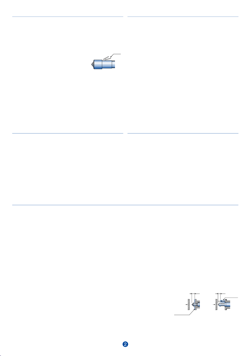
For the switches without stopper
・Do not excessively press the plunger to the stroke end. It may
cause malfunction due to impact.
If the switch does not feature a stopper surface, stop it before it
reaches the end of the stroke.
・If there is possibility to press the plunger to the stroke end, install
a separate stopper to prevent malfunction.
Within stroke
Stopper
Work
piece
Within stroke
Stopper
surface
Work
piece
■Electrical
・Use under the specified contact rating.
・I/F units with a built-in contact point protection circuit are effective for
adverse condition environments where overcurrent may flow. Such
environments may involve, regardless of the presence of contact
points, inductive loads with coils (such inductive loads mainly mean
relay coils, motors, solenoids, many of which require a current of 30mA
or more when driven and generate counter-electromotive force when
switched OFF).
・Since operating errors may occur due to induction when high-voltage
lines or power lines are wired within the same conduit or duct as
switch wires, wire them in separate ducts.
・When using the switch with LED, keep the current below 10mA.
・Chattering may occur when opening and closing the circuit with
dry contacts regardless of whether the switch has a snap action
mechanism. Take the first signal as a judgment signal.
Connecting to a load
・Do not attempt to drive an inductive load directly with these
switches. Direct driving can damage the switching parts and
semiconductors of the internal circuitry. In case of driving an
inductive load, connect a surge absorber in parallel with the load,
and connect an external load such as a relay or transistor allowing an
adequate flow of current for load driving.
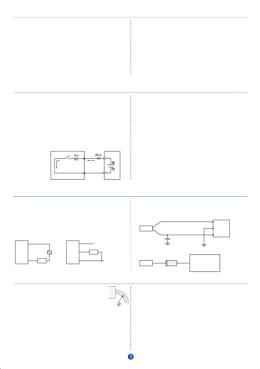
・Connect the switch in the manner shown in the diagram below.
・Limit the LED forward current to about 10mA by inserting a resistor.
・Resistance value = (power supply voltage - LED forward voltage) ÷
current = (24-2) ÷ 0.01 = 2KΩThe LED forward voltage is about 2V.
・The resistor may be installed on the DC 24V or 0V side.
・The LED glows when the circuit is closed. Switch operation is
normal.
・In case of using a sequencer, a resistor is not required if the outflow
current of the sequencer is about 7mA.
・Operation might not be properly confirmed using a digital test
(multi-meter)
Confirming operation by using resistance
・Set the tester to a resistance range of x 10, and connect the minus
lead of the tester to the switch output (brown), and connect the plus
lead of the tester to the switch 0V (blue).
・The deflection of the tester needle indicates around 0W when the
switch plunger is pushed in and roughly infinity (•) when switch tip is
returned.
Confirming operation by using voltage
・Set the tester to a voltage range of 50V and measure the voltage
between the switch output (white) and 0V (blue).
・For NPN output type, when the tip of the switch is pressed, the
indicator of the tester changes from 24V down close to 0V.
・For PNP output type, when the tip of the switch is pressed, the
indicator of the tester changes from 0V up close to 24V.
■Confirmation of switch operation
Current
24 V
power supply
■Wiring Precautions
・Do not pull or twist the cable with excessive force.
(Max.30N (3kgf)). The bending radius of the cable
should be R7 or larger.(except for heat resistance
cable)
・If you want to extend the cord on site, please make
the distance as short as possible as it will otherwise be susceptible to
the increase in the residual voltage and waveform distortion and
induction due to the influence of the line resistance and line-to-line
capacity. In addition, please use the cab tire cord with the
cross-sectional area of 0.2 mm²or more.
・As the wiring of the high-voltage line or power line with the switch will
cause malfunction by induction if it is done in the same pipe or duct,
please make sure that different routes are used.
・Cabtyre cables are used as robot cables without any safety
compromise since the working voltage and current are low, though
cabtyre cables are not applicable to UL, CSA, EN or other safety
standards.
・If waterproofing is required, please mold the terminal so that there will
be no exposed portion.
・Use wire braid or protective tube when using under harsh environment
such as where there are scattering of cutting chips.
■Precautions for Switch Connection
NG
Always make sure to turn off the power before installing or
removing switches.
This is to prevent damage to the device caused by improper wiring
or short-circuits of output lines.
Application of an excessive voltage or application of an alternating
current power supply (AC 24 V or higher) to sensors using a direct
current power supply has the risk of damaging the switch.
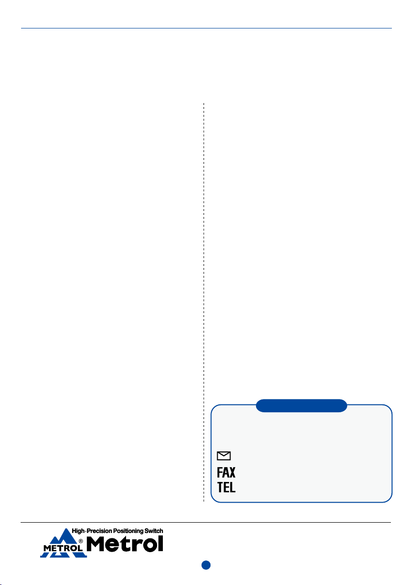
GND
Either ground the switch with a switching power supply in close
proximity to the switch or ground through a capacitor (approx.
0.1~0.47 μF)for the purpose of lowering the impedance of the frame
in order to increase the resistance to entrance of induction noise by
servo drivers or similar devices.
Alternatively, attach a ferrite core to the switch cable.
(0.1〜0.47μF)
FG
0V
+V
Switch Switch
Switch
Switch
Brown
Black
Blue
Brown
Blue Load
Load
Voltage of +24 V
or higher (
×
)
Ferrite core
Level conversion
,etc.
・Use in the environment in where cuttings and dust don't prevent
switch movement.
・Choose protective cover option in case cutting may damage the
rubber boot.
・An extra cover is recommended to avoid direct hit by high-pressure
coolant or heavy cuttings. Periodically remove chips and dust.
Apply force to the movable parts only in the direction of
measurement. Do not apply force in the other direction.
■Operating environment
■Contacting part material
・Even though hardened stainless steel is used as the material of
the contacting part or stopper surface, they are oxidized and may
gather rust under certain conditions.
■Rubber for protective structure(boot, seal, O-ring)
・Rubbers for some products are intended for water-soluble cutting
oil (Alkaline). For oily, chlorine-base, coolants and other
chemicals, consult METROL for assistance.
・The rubber material for High-accuracy MT-Touch Switch is for
both oily and water-soluble coolants.
・Rubber might be hardened when the ambient temperature is low.
When the contact is depressed for a long period of time, it might
take longer time for the contact to return the original position.
■Installation
・Ensure that the threaded part of the switch is not bent during
installation.
・When using fixing screws, do not tighten the screws with
excessive force. That may distort the switch shape or restrict the
movement of the plunger. If the fixing screws are damaged, the
switch can be stuck and difficult to be detached.
・When the switch with a protective cover is
installed horizontally, an extra cover is
needed separately to prevent coolant or
cuttings from entering inside and getting
piled up on the switch.
・Do not subject cable or core wire cable to excessive pulling or
twisting of 30N or more. The bending raduis should be at least R7.
(except for heat resistance cable)
・Do not swing the switch by grabbing the wires or its attaching
portion when installing (especially when the wire is perpendicular
to the switch).
・When installing it with several cables, hold the switch to avoid the
cables from being pulled by weight.
GM-10-2ES-K001
Metal
cutting
■How to use
・Objects shall be aligned straight ahead for the metal bearing
plunger type. (The angle must be within ±3 degrees when high
precision is required such as when using a high precision switch,
or when judging existence detection or ON/OFF.)
・For slide, deflection angle, or offset contacts, select bearing or ball
contact or lever type.
・When the plunger is pushed straight by the detected object, do
not allow the object to abruptly slide away, as it will cause the
plunger to snap back. Note that this may cause failure of the
bearing and built-in switching part.
・Please also note that forcing the plunger in by your fingers and
letting go (snapping it back out) may also cause failure of the
internal contact point.
・Because offset distance (misalignment with axis of the plunger)
should be shorter than 5mm, the maximum diameter for detecting
surface is 10mm for the plunger type with plain bearing.
(Feed speed: 50 mm/min, push-in amount: 1 mm)
・In case the detected surface is angled or ragged, note that the
switch may fail to operate properly or cause malfunction.
・If the contacting part is worn away depending on conditions, the
signal point becomes different. When designing the detected
objects, give consideration to its angle, chamfer and roughness
so that the contacting part holds up longer. (Mainly for sliding
touch type)
・Normally-close (NC) type structure might cause chattering
depending on the roughness of workpiece surface and
environment used (i.e. vibration and contacting speed). In such
case, please select Normally-open (NO) type switch.
・Use it with the operating speed of 50 to 200 mm/m when
precision is required.
For the switches without stopper
・Do not excessively press the plunger to the stroke end. It may
cause malfunction due to impact.
If the switch does not feature a stopper surface, stop it before it
reaches the end of the stroke.
・If there is possibility to press the plunger to the stroke end, install
a separate stopper to prevent malfunction.
Within stroke
Stopper
Work
piece
Within stroke
Stopper
surface
Work
piece
■Electrical
・Use under the specified contact rating.
・I/F units with a built-in contact point protection circuit are effective for
adverse condition environments where overcurrent may flow. Such
environments may involve, regardless of the presence of contact
points, inductive loads with coils (such inductive loads mainly mean
relay coils, motors, solenoids, many of which require a current of 30mA
or more when driven and generate counter-electromotive force when
switched OFF).
・Since operating errors may occur due to induction when high-voltage
lines or power lines are wired within the same conduit or duct as
switch wires, wire them in separate ducts.
・When using the switch with LED, keep the current below 10mA.
・Chattering may occur when opening and closing the circuit with
dry contacts regardless of whether the switch has a snap action
mechanism. Take the first signal as a judgment signal.
Connecting to a load
・Do not attempt to drive an inductive load directly with these
switches. Direct driving can damage the switching parts and
semiconductors of the internal circuitry. In case of driving an
inductive load, connect a surge absorber in parallel with the load,
and connect an external load such as a relay or transistor allowing an
adequate flow of current for load driving.
・Connect the switch in the manner shown in the diagram below.
・Limit the LED forward current to about 10mA by inserting a resistor.
・Resistance value = (power supply voltage - LED forward voltage) ÷
current = (24-2) ÷ 0.01 = 2KΩThe LED forward voltage is about 2V.
・The resistor may be installed on the DC 24V or 0V side.
・The LED glows when the circuit is closed. Switch operation is
normal.
・In case of using a sequencer, a resistor is not required if the outflow
current of the sequencer is about 7mA.
・Operation might not be properly confirmed using a digital test
(multi-meter)
Confirming operation by using resistance
・Set the tester to a resistance range of x 10, and connect the minus
lead of the tester to the switch output (brown), and connect the plus
lead of the tester to the switch 0V (blue).
・The deflection of the tester needle indicates around 0W when the
switch plunger is pushed in and roughly infinity (•) when switch tip is
returned.
Confirming operation by using voltage
・Set the tester to a voltage range of 50V and measure the voltage
between the switch output (white) and 0V (blue).
・For NPN output type, when the tip of the switch is pressed, the
indicator of the tester changes from 24V down close to 0V.
・For PNP output type, when the tip of the switch is pressed, the
indicator of the tester changes from 0V up close to 24V.
■Confirmation of switch operation
Current
24 V
power supply
■Wiring Precautions
・Do not pull or twist the cable with excessive force.
(Max.30N (3kgf)). The bending radius of the cable
should be R7 or larger.(except for heat resistance
cable)
・If you want to extend the cord on site, please make
the distance as short as possible as it will otherwise be susceptible to
the increase in the residual voltage and waveform distortion and
induction due to the influence of the line resistance and line-to-line
capacity. In addition, please use the cab tire cord with the
cross-sectional area of 0.2 mm²or more.
・As the wiring of the high-voltage line or power line with the switch will
cause malfunction by induction if it is done in the same pipe or duct,
please make sure that different routes are used.
・Cabtyre cables are used as robot cables without any safety
compromise since the working voltage and current are low, though
cabtyre cables are not applicable to UL, CSA, EN or other safety
standards.
・If waterproofing is required, please mold the terminal so that there will
be no exposed portion.
・Use wire braid or protective tube when using under harsh environment
such as where there are scattering of cutting chips.
■Precautions for Switch Connection
NG
Always make sure to turn off the power before installing or
removing switches.
This is to prevent damage to the device caused by improper wiring
or short-circuits of output lines.
Application of an excessive voltage or application of an alternating
current power supply (AC 24 V or higher) to sensors using a direct
current power supply has the risk of damaging the switch.
GND
Either ground the switch with a switching power supply in close
proximity to the switch or ground through a capacitor (approx.
0.1~0.47 μF)for the purpose of lowering the impedance of the frame
in order to increase the resistance to entrance of induction noise by
servo drivers or similar devices.
Alternatively, attach a ferrite core to the switch cable.
(0.1〜0.47μF)
FG
0V
+V
Switch Switch
Switch
Switch
Brown
Black
Blue
Brown
Blue Load
Load
Voltage of +24 V
or higher (
×
)
Ferrite core
Level conversion
,etc.
GM-10-2EH-K001
Terms of Warranty
Before using, we would like to request that our customers have an understanding of warranty policy,
functions and specifications of applicable products as indicated in our catalogs, instruction manuals and
web site to ensure that they are used properly under specified conditions.
1) Applicable Products
The warranty defined below is applicable to products manufactured and sold by METROL (to be referred to as the
"applicable products").
2) Warranty Period
The warranty for applicable products is valid for one year
and three months from the original delivery date to the
location designated by the customer.
*Durability, life time and repeatability are described based
on our test conditions. Please note that the performance is
not guaranteed under your usage environment.
3) Range of Coverage
a. A replacement product will be provided on an exchange
basis or the malfunctioned product will be repaired free of
charge within the warranty period. If the product is or
becomes defective and that at the sole discretion of
METROL, the defects due to faulty materials or workman-
ship.
However, applicable products will not covered by the
warranty in the case of the following malfunctions even
within the warranty period.
( I ) Malfunctions occurred due to use of a product in a
manner that deviates from standards, specifications,
environments, usage procedures or usage precautions
described in the catalog, instruction manual or
specifications.
( II ) Malfunctions having occurred for reasons other than
those attributable to the delivered product.
( III ) Malfunctions having occurred due to disassembly,
modifications or repairs made by someone else other
than the Metrol representative.
(IV) Malfunctions or damage that results from external
causes outside our control which shall include
accident fire disaster, other natural disaster or other
force majeure.
b. The range of coverage is limited to warranty of the
applicable product only, and any other secondary loss or
damage resulting from the malfunction of an applicable
product is not covered by the warranty.
c. Please be aware that we don't offer installation,
de-installation on-site confirmation and repairs.
4)Applications
Applicable products are designed and manufactured as
general-purpose products used in ordinary industrial
environments.
In the case of incorporating an applicable product in an
apparatus, machine or system, please confirm the suitability of
the application along with any related standards, regulations
and restrictions.
With respect to the applications indicated below in particular,
customers are requested to conduct necessary tests on an
actual product in advance regarding usage conditions and
other details.
a. Applications for which usage conditions or environment are
outside those presumed by the manufacturer or applications
unable to be confirmed as being appropriate by the
manufacturer when using applicable products.
b. Applications likely to have an effect on human life or property
(such as nuclear power equipment, transportation machinery
or medical devices), applications used in public utilities (such
as electricity, gas or water lines), or applications applying
correspondingly thereto.
c. Applications in harsh environments (special environments
requiring heat resistance, vacuum and the like)
5) Attention
・The contents of this catalog, including specific models and,
specifications, and any other contents, are subject to change
without notice at METROL’s sole discretion.
・Durability, life time and repeatability are described based on
our test conditions. Please note that the performance is not
guaranteed under your usage environment.
・Second characteristic number of the protective structure (IP)
represents the waterproofness against water. This
waterproofness may not apply to the coolant.
Help desk
www.metrol.co.jp/en
+81-42-528-1442
+81-50-5558-7366
We accept inquiry regarding sensor selection, exclusive
specification, and technical matter through website, Fax,
and Tel listed below.
E-mail
METROL CO., LTD.
1-100 Takamatsu-cho Tachikawa, Tokyo 190-0011 JAPAN
Tel: +81 50 5558 7366 / Fax: +81 42 528 1442
Website: www.metrol.co.jp/en
TOKYO JAPAN
The specifications and descriptions are subjected to change without notice due to improvements in products.
4
This manual suits for next models
8


