10 Operator’s Manual
SAFETY SIGNS
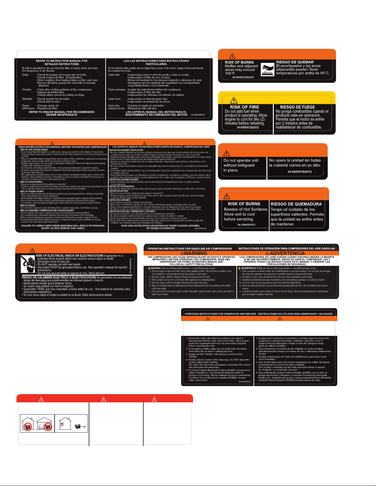
34-1284
34-0826
34-0599
34-1616
CAUTION/PRECAUCIÓN
Do not add fuel when
product is operating. Allow
engine to cool for two (2)
minutes before refueling.
34-0599/07262012
RISK OF FIRE
RIESGO DE FUEGE
No ponga combustible cuando el
producto este en operacion.
Permita que el motor se enfrie
por 2 minutos antes de
reablastecer de combustible.
WARNING/ADVERTENCIA
RISK OF BURNS
Muffler and adjacent
areas may exceed
150°F.
RIESGO DE QUEMAR
El amortiguador y las areas
adyacentes pueden Tener
temperaturas por arriba de 65°C.
34-0598/07262012
34-0598
Beware of Hot Surfaces.
Allow unit to cool
before servicing.
RISK OF BURNS RIESGO DE QUEMADURA
Tenga ud cuidado de los
superficies calientes. Permita
que la unidad se enfrie antes
de mantener.
34-1284/091012
WARNING/ADVERTENCIA
34-1616/091012
RISK OF ELECTRICAL SHOCK OR ELECTROCUTION! A generator is a
potential shock hazard which can result in serious injury or death.
• Generator must be kept dry.
• Do NOT operate unit with wet hands.
• Generator MUST be grounded before use. See operators manual for specific
instructions.
• Do not use around water or expose to rain. Store indoors.
RIESGO DE CALAMBRE ELECTRICO O ELECTROCUCION! Un generador es un potencial
riesgo de descarga que puede resultar en lesiones graves o muerte.
• Generadores tienen que mantener secos.
• No opere esta unidad con manos mojados.
• Generador TIENE que sea conectado a tierra antes de uso. Vea manual de operador para
instrcciones especificos.
• No use cerca aqua ni tenga la unidad en la lluvia. Débe almecenaria dentor.
WARNING / ADVERTENCIA
WARNING/ADVERTENCIA
34-0826/07262012
No opere la unidad sin todas
la cubierta correa en su sitio.
Do not operate unit
without beltguard
in place. 34-0826/07262012
No opere la unidad sin todas
la cubierta correa en su sitio.
Do not operate unit
without beltguard
in place.
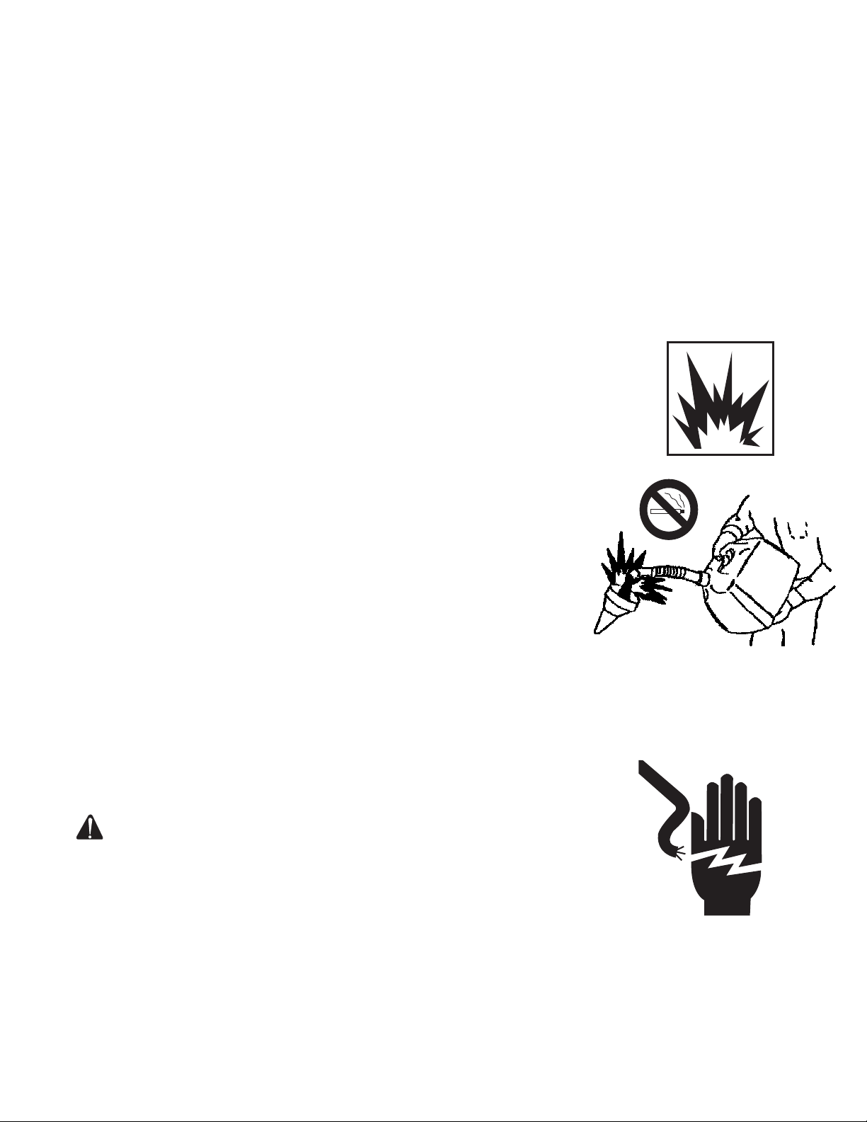
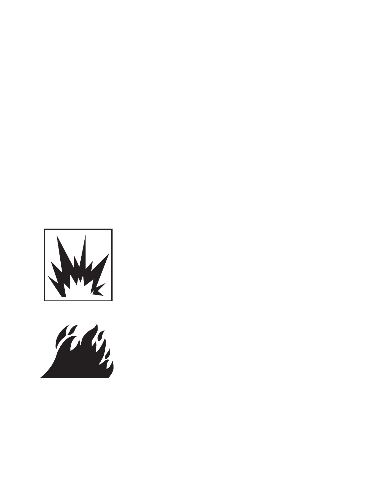
RISK OF FIRE OR EXPLOSION!
• Do not spray flammable liquid in a confined area. Spray area must be well ventilated. Do not smoke
while spraying or spray where spark or flame is present. Keep compressors as far from spraying area as
possible.
• When a combustible liquid is sprayed there may be danger of fire or explosion, especially in a closed area.
• Arcing parts. Keep the unit at least 6m away from explosive vapors.
• Engine creates sparks. Do not operate in flammable environment. Follow all instructions and warnings
supplied with material to be sprayed.
• Do not smoke while filling engine fuel tank. Follow all fueling instructions in operator's manual.
• Air tanks may explode if not properly maintained. To prevent weakening of tanks caused by corrosion,
drain tanks after each use.
• This equipment incorporates parts, such as snap switches, receptacles, produce arcs or sparks and,
therefore, when located in a garage, it should be in a room or enclosure provided for the purpose, or
should be 18 inches (457mm) or more above the floor.
RISK OF ASPHYXIATION!
• Never use compressed air for breathing or respiration!
• Gasoline engines produce carbon monoxide; a poisonous, odorless gas which may cause death! Do not
start or operate compressor in an enclosed area. Area must be well ventilated.
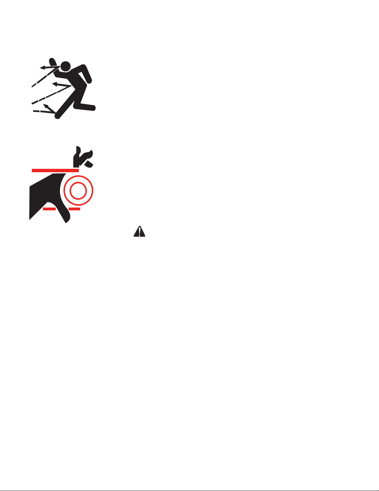
RISK OF SEVERE INJURY!
• Before servicing gasoline unit, disconnect spark plug wire to prevent unit from starting unexpectedly.
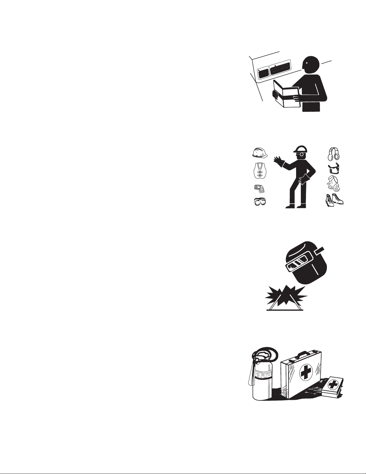
• Wear safety glasses/face shields at all times.
• Never operate with beltguard removed. If guard becomes damaged, repair or replace before operating.
• Do not remove any air line or tank connections before relieving air pressure in the tank(s).
• Loose debris can be propelled at high speeds. Never direct air stream towards yourself or others.
RISK OF BURNS!
• Do not touch compressor head, discharge lines or engine components. Cool before servicing.
RISK OF DAMAGING COMPRESSOR AND CAUSING INJURY!
• Do not operate at pressure or speed in excess of manufacturer's recommendations.
• Do not operate with components rated less than the pressure marked on the nameplate.
Follow required maintenance procedures and intervals listed in the operator's manual. Service
should be performed only by qualified personnel. Compressor requires good ventilation to operate
properly. Use only factory replacement parts.
RIESGO DE INCENDIO O EXPLOSION!
• No rocie el líquido inflamable en una áred confinada la área para rociar tiene que ser bien ventilado. No fume cuando está
rociando ni vocie donde hay incendio o centella. Ponga los compresores lejos de la area de vociar si es posible.
• Cuando un liquido inflamable está rociado hay posible peligro de incendio o explosión, especialmente en un lugar cerrado.
• Partes de arco. Ponga la unidad menos de 6m lejos de los vapores explosívos.
• El motor se causan las centellas. No use en un lugar inflamable. Siga usted las instrucciones y advertencias con el
material para rociar.
• No fume cuando está llenando el tanque de combustible siga todas las instrucciones de combustible en el manual del
operador.
• Los tanques del aire puede explotar si no se mantenga bien. Para evitar la debilitación de los tanques del corrosión, drene
los tanques cada uso.
• Este equipo tiene los partes com interruptor de resortes, receptaculos, se producen o centellas y por eso, cuándo está en
un garaje, lebe estar en un cuarto o un encerramiento por este, o debe estar 18 pulgadas o (457 mm) o encima del suelo.
RIESGO DE LESIONES GRAVES!
• Antes de mantenerse la unidad gasolina, desconecte el hilo de la telegrafista para evitar la unidad a arrancar
inesperadamente.
RIESGO DE QUEMADURAS!
• No toque la cabeza del compresor, lineas del descargo o partes del motor. Permita que se enfrie antes del servicio.
RIESGO DE ASFIXIA!
• Nunca se use el aire del compresor para respirar o respiración!
• El motor produce carbón monóxido un vapor tóxico un olor que se puede causar morir. No use o arranca un lugar
encerrado. El área debe ser bien ventilado.
REISGO DE LESIONES!
• Lleve gafas de seguridad o blindaje todo el tiempo.
• Nunca opere sin cinturon de protección. Si el cinturon está dañado repare o reemplace antes de usarlo.
• Nunca saque cualquier linea del aire o conexione del tanque antes de eliminando del sion aire en los tanques.
• No dirija el rociado de alta presión hacia ninguna persona ni hacia usted mismo. Escombros se vuelan rapído.
RIESGO DE DAÑO DEL COMPRESOR O LESIONES!
• No opera a un presión o una velocidad más que se recomienda en el manual.
• No opera con partes clasifican menos de la presión que ha escrito en el plato de nombre.
Siga los procedimientos de mantenimiento y intervalos que se dicen en el manual de operador.
Servicio debe hacer solemento por las personas calificados. Para funcionar correctamente, necesita un lugar bien
ventilado. Use solamente partes para reemplacer de la fábrica.
READ ENTIRE INSTRUCTION MANUAL BEFORE OPERATING AIR COMPRESSOR! LEA USTED EL MANUAL DE INSTRUCCIONES ANTES DE USAR EL COMPRESOR DEL AIRE!
SI NO SIGA USTED ESTAS ADVERTENCIAS PUEDE CAUSAR LESIONES.
NO SAQUE LA ETIQUETA!
FAILURE TO COMPLY WITH THESE WARNINGS WILL RESULT IN PERSONAL
INJURY. DO NOT REMOVE THIS LABEL! 34-1615/091012
WARNING ADVERTENCIA
34-1615
WARNING: Cancer and Reproductive Harm — www.P65warnings.ca.gov/
1. Flip the toggle on top of the pilot valve to the upright position. This provides a loadless start.
The compressor will unload and allow the engine to start easier.
2. Start the engine. (Refer to Engine Manual accompanying this unit.)
3. When engine has run for 1-2 minutes, flip toggle back to original position.
4. Stop the engine. (Refer to Engine Manual accompany this unit.)
5. Drain air from the tanks by releasing air with an attached air tool or by pulling on the safety
relief valve rings.
6. Once pressure in the tanks register under 10 pounds, open the drain valve under each tank to
drain any moisture.
ADVERTENCIA: Peligro de cáncer y daño reproductivo — www.P65warnings.ca.gov/
1. Eche la palanca acodada encima de la válvula pilota a la posición vertical. Con este hay un arranque
sin carga. El compresor va a descargar y permitir el motor a arrancar facilmente.
2. Arranque el motor. (Lea el manual del motor que está acompañado está unidad)
3. Cuanda la unidad funciona para 1-2 minutos, mueva la planaca acodada a la posicion original.
4. Cierre el motor. (Lea el manual que está acompañado está unidad)
5. Drene los tanques del aire con un instrumento acompañado del aire o tire los anillos de la válvula
segura.
6. Cuando la presión en los tanques es menos de diez libras, abre la válvula debayo de cada tanque
para des aguar cualquier humedad. 34-1286/060421
34-1286
LEA LAS INSTRUCCIONES PARA INSTRUCCIONES
PARTICULARES.
LEA USTED EL MANUAL DEL MOTOR PARA EL
MANTENIMIENTO RECOMENDADO DEL MOTOR.
Si la unidad está usado en un lugar bien sucio o de polvo, haga la frecuencia de
los examenes más.
Cada día: •Inspecciòne para el nivel de aceite y vias de aceite.
•Inspecciòne el filtro de aire (si hay).
•Drene la humidad de los tanques cada día o despúes de usar.
•Asegúrese que las guardas de seguridad son acompañados
seguridademente y correctamente.
Cada semana: •Limpie las superficies enfries del compresor.
•Inspeccióne el filtro del aire.
•Inspeccióne las válvulas con tirando los anillos.
Cada mes: •Inspeccióne la sistema para vías.
•Inspeccióne la tensión de la correa.
Cada dos •Cambie el aceite de la bomba.
cientos horas: •Reemplace filto del aire.
REFER TO INSTRUCTION MANUAL FOR
DETAILED INSTRUCTIONS.
REFER TO ENGINE MANUAL FOR RECOMMENDED
ENGINE MAINTENANCE.
If unit is operated in an excessively dirty or dusty area, increase
the frequency of all checks.
Daily: •Check for proper oil level(s) and oil leaks.
•Check engine air filter. (if applicable)
•Drain moisture from tank(s) daily or after each use.
•Ensure all safety guards are correctly & securely
attached.
Weekly: •Clean the cooling surfaces of the compressor.
•Inspect air intake filter.
•Check safety valves by pulling on rings.
Monthly: •Check system for air leaks.
•Check belt tension.
Every •Change pump oil.
200 hours: •Replace air filter.
34-1285/091012
MAINTENANCE INSTRUCTIONS INSTRUCCIONES DE MANTENIMIENTO
34-1285
DANGER DANGER PELIGRO
34-1916/083012
Using a generator indoors CAN KILL YOU IN MINUTES.
Generator exhaust contains carbon monoxide. This is a
poison you cannot see or smell.
NEVER use inside a home
or garage, EVEN IF doors
and windows are open.
Only use OUTSIDE and far
away from windows, doors,
and vents.
Utilizando un generador adentro
PUEDE MATARLE EN MINUTOS.
El escape de generador contiene
monóxido de carbono. Este es un
gas tóxico que usted no puede ver ni
puede oler.
Nunca utilice dentro de un hogar ni el
garaje, INCLUSO SI puertas y
ventanas estén abiertas.
Solo utilice AFUERAS y lejos de
ventanas abiertas, las puertas, y
descargas.
L'utilisation d'un groupe électrogène à
l'intérieur PEUT VOUS TUER EN
QUELQUES MINUTES.
Le gaz d'échappement du groupe
électrogène contient de l'oxyde de
carbone. C'est un gaz toxique que l'on
ne peut pas voir ou sentir.
Ne JAMAIS utiliser à l'intérieur d'une
maison ou d'un garage, MÊME SI les
portes et fenêtres s'ont ouvertes.
N'utiliser qu'à l'EXTÉRIEUR et bien éloigné
des fenêtres, portes, et conduits d'aération.
34-2666
34-1916
34-2666/091012
OPERATING INSTRUCTIONS FOR GENERATOR AND WELDER
GENERATOR / WELDER CAN CAUSE SERIOUS INJURY OR
DEATH IF OPERATED IMPROPERLY. BEFORE OPERATING
THIS UNIT READ AND UNDERSTAND THE ENTIRE OPERA-
TOR’S MANUAL AND FOLLOW ALL SAFETY
PRECAUTIONS.
1. Ensure the unit is grounded according to the owner’s
manual and national, state, and local codes. Wear proper
protective equipment and clear the area of any hazards
before operating the unit.
2. To maximize welder output, do not weld while simultane-
ously filling the air tank or utilizing air tools.
3. Toggle the Full Throttle / Idle Switch to select to Full
Throttle.
4. Rotate switch to select weld amperage. Do NOT adjust the
control output while welding
Use table and electrode packaging to determine the correct
size electrode and amperage.
5. For Direct Current Electrode Positive (DCEP), connect work
cable to Negative (−) terminal and electrode holder to
Positive (+) terminal. (thicker material and more penetration)
For Direct Current Electrode negative (DCEN), reverse
cable connections.
INSTRUCCIONES DE UTILIZAR PARA GENERADOR Y SOLDADOR
EL GENERADOR/SOLDADOR PUEDE CAUSAR LA HERIDA SERIA
O LA MUERTE SI UTILIZADO INCORRECTAMENTE. ANTES DE
UTILIZAR ESTA UNIDAD, LEA Y ENTIENDA EL MANUAL DEL
OPERADOR ENTERO Y SIGA TODAS LAS
PRECAUCIONES DE SEGURIDAD.
1. Asegure que la unidad es conectada a la tierra según el manual del
propietario y códigos nacionales, estatales, y locales. Lleve el
equipo protector apropiado y limpie el área de cualquier riesgo
antes de utilizar la unidad.
2. Para maximizar el rendimiento de soldador, no solde mientras
simultáneamente llenando el tanque de aire o utilizando instrumentos
de aire.
3. Cambie el Interruptor de Toda Velocidad/Ocioso para seleccionar
Toda Velocidad.
4. Gire el interruptor para seleccionar el amperaje de soldar. NO ajuste
el rendimiento de control mientras soldando.
Use la tabla y embalaje de electrodo para determinar el tamaño
de electrodo y el amperaje correctos.
5. Para el Electrodo Corriente Directo Positivo (DCEP), una el cable de
trabajo al terminal (−) Negativo y el tenedor del electrodo al terminal
Positivo (+) . (material más grueso y más penetración) Para el Electrodo
Corriente Directo Negativo (DCEN), invierta uniones de cable.
WARNING ADVERTENCIA