Motor Guard Magna Stitcher MS-2500 User manual

MAGNA-STITCHERTM
Plastic Repair System
Model MS-2500
WARNING: Read and understand all instructions before attempting to operate tool.
Failure to follow instructions may result in electric shock, fire and/or serious
personal injury.
IMPORTANT SAFETY INSTRUCTIONS
To reduce the risk of serious
injury and/or property damage,
observe all warnings and
instructions while operating the
tool. Keep work area clean and well
lit. Maintain tool in top condition and
obtain service from manufacturer if
tool malfunctions. Use only
accessories and replacement parts
that are provided by the
manufacturer.
This tool must be connected to a
properly grounded outlet installed
in accordance with all local codes
and ordinances. Never remove the
grounding prong or modify the plug
in any way. Do not use adapter
plugs. Consult an electrician if you
are in any doubt as to whether the
plug is properly grounded. Avoid
bodily contact with grounded
surfaces.
Always wear proper personal
protection when operating welder.
A full face shield per ANSI Z87.1-
2003 standard is required at all times
to protect face and eyes against
injury from flying parts. Adequate
gloves and clothing are required to
reduce the risk of burns. Allow parts
to cool before handling.
Do not operate tool in explosive
atmospheres, such as in the
presence of flammable liquids,
gases or dust. Welders create
sparks which may ignite dust or
fumes. Use in well ventilated areas
only. Welders generate heat which
can ignite surrounding materials
causing fires.
SAVE THESE INSTRUCTIONS
IF YOU HAVE ANY QUESTIONS ABOUT THE OPERATION OF PRODUCT CALL TOLL FREE
800-227-2822
8:00 am to 5:00 pm - Pacific Time - Monday through Friday
INSTRUCTIONS

Page 2
APPLICATION
The Motor Guard Magna StitcherTM Plastic Repair System can be used to perform structural repair of
many plastic parts. The MS-2500 works by welding a rigid stainless steel stake into the surface of the
plastic resulting in a permanent repair of the crack. Repairs can be made on flat surfaces, tabs,
holes, ribs, inside and outside corners.
The Magna StitcherTM System can be used to repair Bumpers, Fascias, Spoilers, Headlamp Brackets,
Radiator Brackets, Interior Components, Underbody Structures, Wheel Wells, Panel Mounting Tabs
and any thermoplastic part. This economical tool can also be used for quick, on-the-vehicle repairs
such as mounting tabs, underbody components and other out-of-sight components. Simply stitch and
go!
IMPORTANT: Read and understand all warnings and instructions prior to use.
PREPARING MAGNA-STITCHER SYSTEM FOR USE
Connect the unit to an approved power supply, paying careful attention to the safety instructions on
the previous page. If an extension cord is needed, it must be a three-wire, grounded cord of the
proper amperage. This unit is designed for indoor use only in a clean, dry environment.
Turn the unit on by switching the main Power Switch (1) to the On position. Select a power level by
rotating the Level Knob (2) to one of the three power positions:
Low Setting
(Green LED)
For thin sections and detailed work
Medium Setting
(Yellow LED)
For general repairs
High Setting
(Red LED)
For thicker sections and heavy work
The Work Lamp (4) will illuminate in any of the three power positions and will remain on whether the
Trigger Button (3) is depressed or not. To prevent eye damage, do not stare directly into the
light beam and do not point the light directly at others.
Choose proper stake type according to area to be repaired (see table on back page).
PREPARATION OF WORK AREA
Prepare area to be repaired by removing all dirt, oil and dust. Repairs are generally made on the
inside surface of the panel. Removable foil tape may be used on the outer surface to hold the
position while stitching.
Fig. 1

Page 3
Fig. 2
Fig. 3
Fig. 4
Fig. 5
Fig. 6
Fig. 7
GENERAL REPAIR PROCEDURE WITH MAGNA STAKES
Insert stake into Electrodes (5) as shown in Figure 2. Three positions are
available to insert stakes at different angles.
Place stake against surface to be repaired while applying moderate
pressure. Depress the Trigger Button (3) to heat the stake.
While continuing to apply pressure, allow the stake to sink halfway
through the thickness of the work piece. After stake is inserted to proper
depth, twist the stake slightly to allow it to lock into the panel.
Allow the stake to cool for 2 or 3 seconds before removing tool. Trim
exposed ends of stake using wire cutters (Figure 3). Take care while
trimming stakes as flying pieces can cause injury to operator or
bystanders. Eye protection should be worn at all times (See Safety
Instructions).
Complete cosmetic repair on front of panel as needed.
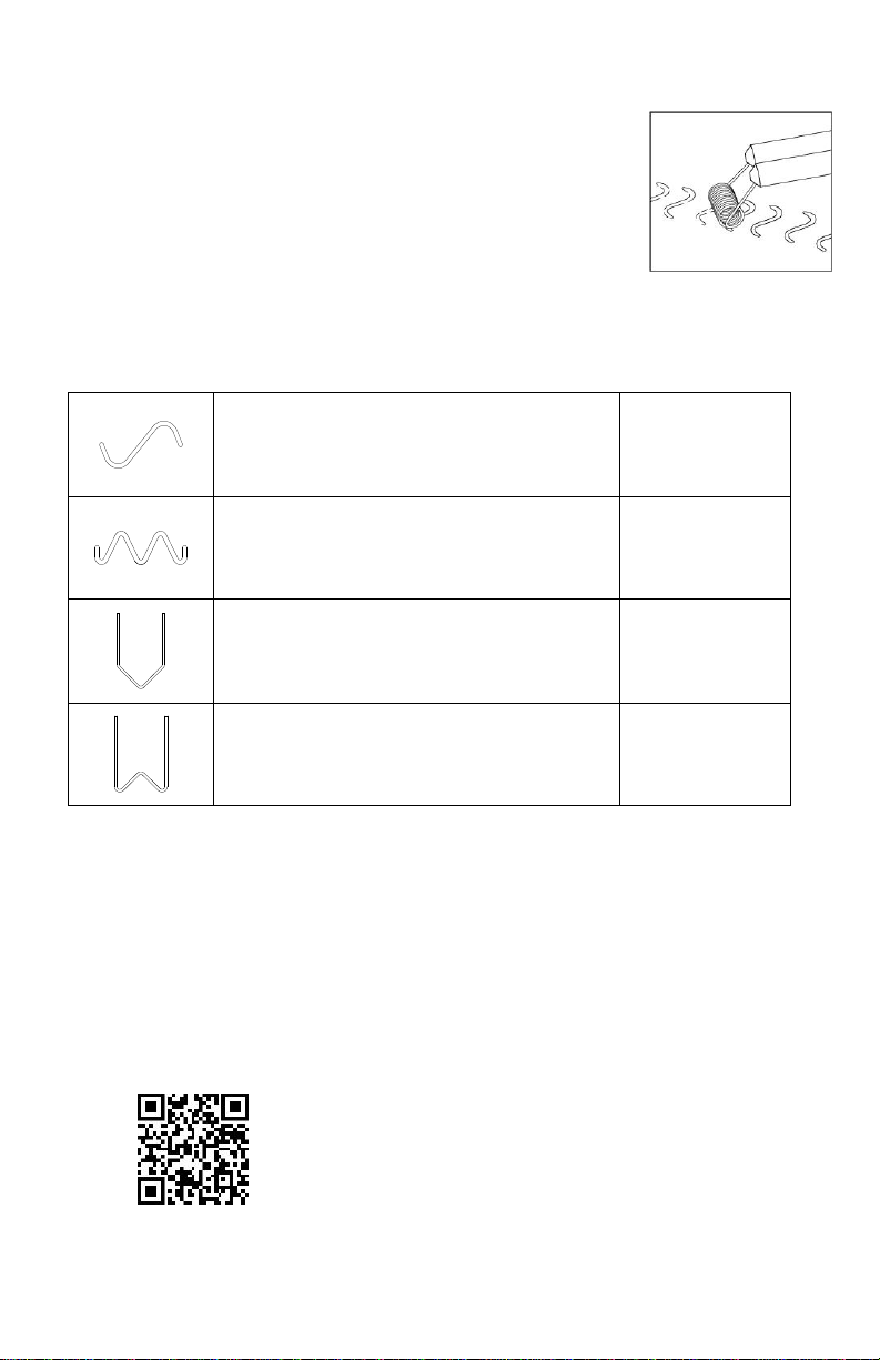
REPAIR OF FLAT AREAS
Prepare area to be repaired per instructions above. Insert an S-Shaped
Magna-StakeTM into the electrodes.
Set stake across crack as shown in Figure 4. Insert stake per instructions above, halfway through
panel thickness, and give stake a slight twist before allowing to cool. Space stakes on 1/2 to 3/4 inch
intervals or as needed for strength.
Trim stake ends and complete repair on front of panel as needed (See Safety Instructions).
REPAIR OF TABS AND THIN SECTIONS
Prepare area to be repaired per instructions above. Insert an M-Shaped
Magna-StakeTM into the electrodes.
Set stake across crack as shown in Figure 5. Insert stake per instructions
above, halfway through panel thickness, and add additional stakes as
needed for strength.
Trim stake ends and complete repair on front of panel as needed (See
Safety Instructions).
REPAIR OF INSIDE CORNERS
Prepare area to be repaired per instructions above. Insert a V-Shaped
Magna-StakeTM (MS2006) into the electrodes.
Set stake across crack as shown in Figure 6. Insert stake per
instructions above, halfway through panel thickness, and give stake a
slight twist before allowing to cool. Space stakes on 1/2 to 3/4 inch intervals or as needed for
strength.
Trim stake ends and complete repair on front of panel as needed (See Safety Instructions).
REPAIR OF OUTSIDE CORNERS
Prepare area to be repaired per instructions above. Insert a W-Shaped
Magna-StakeTM (MS2007) into the electrodes.
Set stake across crack as shown in Figure 7. Insert stake per
instructions above, halfway through panel thickness, and give stake a
slight twist before allowing to cool. Space stakes on 1/2 to 3/4 inch
intervals or as needed for strength.

Page 4
Trim stake ends and complete repair on front of panel as needed (See Safety Instructions).
SURFACE REPAIR WITH IRONING TIP
Ironing tip may be used to smooth rough areas and build up low areas
prior to final repair. Insert Magna-StitcherTM Ironing Tip (MS2045) into the
electrodes as shown in Fig. 8.
Depress Trigger Button (3) to heat the tip.Apply moderate pressure and a
slight rotary motion, allowing the spring-like tip to roll over the area to be
repaired.
Continue until damaged area is smooth and complete repair using
conventional methods.
REPLACEMENT STAKES
S-Shaped Magna-Stake for repair of flat
sections. Rust proof stainless steel.
MS2004 PK/50
MS2014 PK/100
M-Shaped Magna-Stake for repair of tabs and
thin sections. Rust proof stainless steel.
MS2005 PK/50
MS2015 PK/100
V-Shaped Magna-Stake for repair of inside
corners. Rust proof stainless steel.
MS2006 PK/50
MS2016 PK/100
W-Shaped Magna-Stake for repair of outside
corners. Rust proof stainless steel.
MS2007 PK/50
MS2017 PK/100
LIMITED WARRANTY
Motor Guard Corporation assumes the responsibility of providing products that are free from defects in
workmanship and material. Should a product fail due to a defect in workmanship or material, Motor Guard
Corporation will repair or, at its option, replace the product without charge, other than the transportation
charges, provided that the product is returned to the factory, transportation prepaid, within One (1) Year of the
date of purchase. Please contact Motor Guard Corporation for return authorization and shipping instructions.
This limited warranty does not cover normal wear and tear or damage to the product due to neglect, misuse or
accident, nor does it cover any loss, damage or expense, either direct, indirect or consequential, arising from
the non-function of this product.
Scan for Video
Motor Guard Corporation
580 Carnegie Street
Manteca, CA 95337
U.S.A.
Toll Free: (800) 227-2822
info@motorguard.com
Hours: Mon-Fri 8:00 am to 5:00 pm PST
33028
Rev 07/17
Fig. 8
Table of contents
Other Motor Guard Welding System manuals
Popular Welding System manuals by other brands

Migatronic
Migatronic PI 200 AC/DC HP instruction manual

HUGONG
HUGONG POWERTIG 300DPIII owner's manual

Clarke
Clarke MIG 240 Operation & maintenance instructions

Sealey
Sealey MIGHTYMIG170.V2 quick start guide

Walter
Walter SURFOX 305 user guide

Lincoln Electric
Lincoln Electric PIPELINER 11498 Operator's manual