Miad Audio LCPQ 4040 User manual
LCPQ 4040
Discrete 4-band EQ
Operator’s Manual
Version 1.2
MIAD Audio
Aleje Jerozolimskie 137/55
Warsaw, 02-304, Poland
Email: [email protected]
Phone: +48 882 153 350

!
2!
Table of Contents
1.0 LCPQ 4040
1.1 Overview
1.2 Features
1.3 Front Panel
1.4 Rear Panel
2.0 PS 230
2.1 Overview
2.2 Features
2.3 Front Panel
2.4 Rear Panel
3.0 Troubleshooting
4.0 Specifications
4.1 LCPQ 4040 Technical Specifications
4.2 LCPQ 4040 Dimensions
4.3 PS 230 Technical Specifications
4.4 PS 230 Dimensions
5.0 Appendix
5.1 Warranty Registration
5.2 Product Warranty
5.3 Block Diagram
5.4 Frequency Response
5.5 EQ Response Curves
5.6 Recall Sheet

!
3!
Important Safety Instructions
•Please read these instructions.
•Keep these instructions in a safe place.
•Do not operate this unit in the presence of rain, liquids, or condensing
moisture. Liquid entering the product enclosure presents the risk of fire or
electric shock injury.
•Clean only with a dry cloth.
•Do not install near any heat sources such as radiators, heat registers, stoves, or
other devices that produce heat.
•Do not defeat the safety purpose of the polarized or grounding type AC plug.
•Protect both the AC power cord to the power supply and the DC cable
between the power supply and the EQ unit from being walked on or pinched.
•Use only attachments/accessories specified by the manufacturer.
•Unplug this device during lightning storms or when unused for long periods of
time.
•Refer all service to qualified personnel.
WARNING
TO REDUCE THE RISK OF FIRE OR ELECTRIC
SHOCK, DO NOT EXPOSE THIS APPARATUS
TO RAIN OR MOISTURE
DO NOT USE A DAMAGED OR EXCESSIVELY
WORN IEC CABLE TO CONNECT THIS UNIT
TO AC POWER
!
TO DISCONNECT THE UNIT COMPLETELY
FROM THE MAINS, UNPLUG THE UNIT. !
!
!
ATTENTION
Exposure to extremely high noise levels may cause
permanent hearing loss or damage.
!
!

!
4!
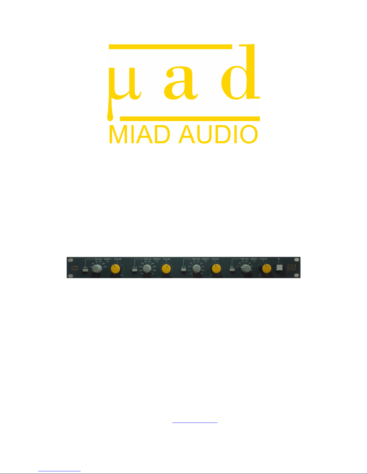
1.0 LCPQ!4040!
!
1.1!Overview!
! !
The LCPQ 4040 is a transformer balanced, high performance all-discrete equalizer
with four passive RLC sections in cascade configuration.
Each band has a variable level control ranging from -12dB to +12dB. The four bands
of equalization offer selectable Shelving/ Bell on the first and fourth band and
selectable HiQ/ LowQ on the second and third band.
Each band can be independently bypassed. When an EQ band is not engaged, the
audio signal still travels through the transformers and the discrete circuit but not
through the RLC circuit and thus the unit can be used as a high quality unity gain line
amp. In addition to the individual bypass, the unit employs a true bypass relay system,
where the input signal is connected directly to the output. When the unit is not
powered (or in situations where the power accidentally goes down), the bypass relay
system is automatically activated and therefore the signal will not disappear.
The LCPQ 4040 features Carnhill high-level audio signal input and output
transformers and a combination of four Carnhill and custom made tapped inductors
(5% tolerance) that were chosen after extended listening tests and measurements.
The unit consists of Grayhill rotary stepped switches for frequency selection, plastic
conductive potentiometers (10% tolerance) for boosting/cutting, Wima polypropylene
(low tolerance) film capacitors in the RLC path, Panasonic audio grade electrolytic
capacitors in the active circuit and Neutrik connectors for the audio and power
connections.
Each unit is hand-built and hand-wired. All the components are chosen and tested
thoroughly for best performance, musicality and long-term reliability.
!
1.2!Features!
! !
•Fully discrete (transistor) circuit
•Transformer (Carnhill) balanced input and output
•Carnhill and custom made tapped inductors
•Thirty four selectable frequencies
•12dB of Gain/ Attenuation per band
•Selectable Shelving/ Bell on Band1 and Band4
•Selectable HiQ/ LowQ on Band2 and Band3
•Individual bypass on each band
•True bypass relay system
•High quality Neutrik XLR connectors
•Low components tolerance for stereo configuration
•Hand-built and hand-wired
•3-year limited warranty

!
5!
1.3!Front!Panel!
!
! !
A. SHELVING/ BELL SWITCH – This switch toggles between Shelving and
Bell shape. When the switch is pressed, the Bell shape is active.
B. OFF – When the FREQ.rotary switch is in the OFF position, the band is
not engaged (i.e. the filter circuit and the LEVEL control are inactive).
However, the audio signal still travels through the discrete circuit and the
audio transformers.
C. FREQ. – This rotary stepped switch determines the frequency point for
each band. The frequency points for each band are as follows:
Band 1: OFF, 45Hz, 65Hz, 100Hz, 180Hz, 330Hz, 470Hz
Band 2: OFF, 180Hz, 220Hz, 270Hz, 330Hz, 390Hz, 470Hz, 560Hz,
680Hz, 820Hz, 1kHz, 1.3kHz
Band 3: OFF, 1.2kHz, 1.5kHz, 1.8kHz, 2.2kHz, 2.7kHz, 3.3kHz, 3.9kHz,
4.7kHz, 5.6kHz, 6.8kHz, 8.2kHz
Band 4: OFF, 3.3kHz, 4.7kHz, 6.8kHz, 10kHz, 15kHz, 23kHz
D. LEVEL – Each band has a high quality continuously variable
potentiometer that controls the amount of gain or attenuation (+/- 12dB).
E. HI-Q/ LOW-Q SWITCH – This switch controls the sharpness of the peak
or dip and it toggles between High Q and Low Q. When the switch is
pressed, the High Q is active.
F. IN – This switch toggles between the active (LED ON) and bypassed
(LED OFF) modes. Since the unit employs a bypass relay system, no
audio signal passes through this switch. Instead, the IN switch is a DC
voltage switch that controls the relays’ state.
!
6!
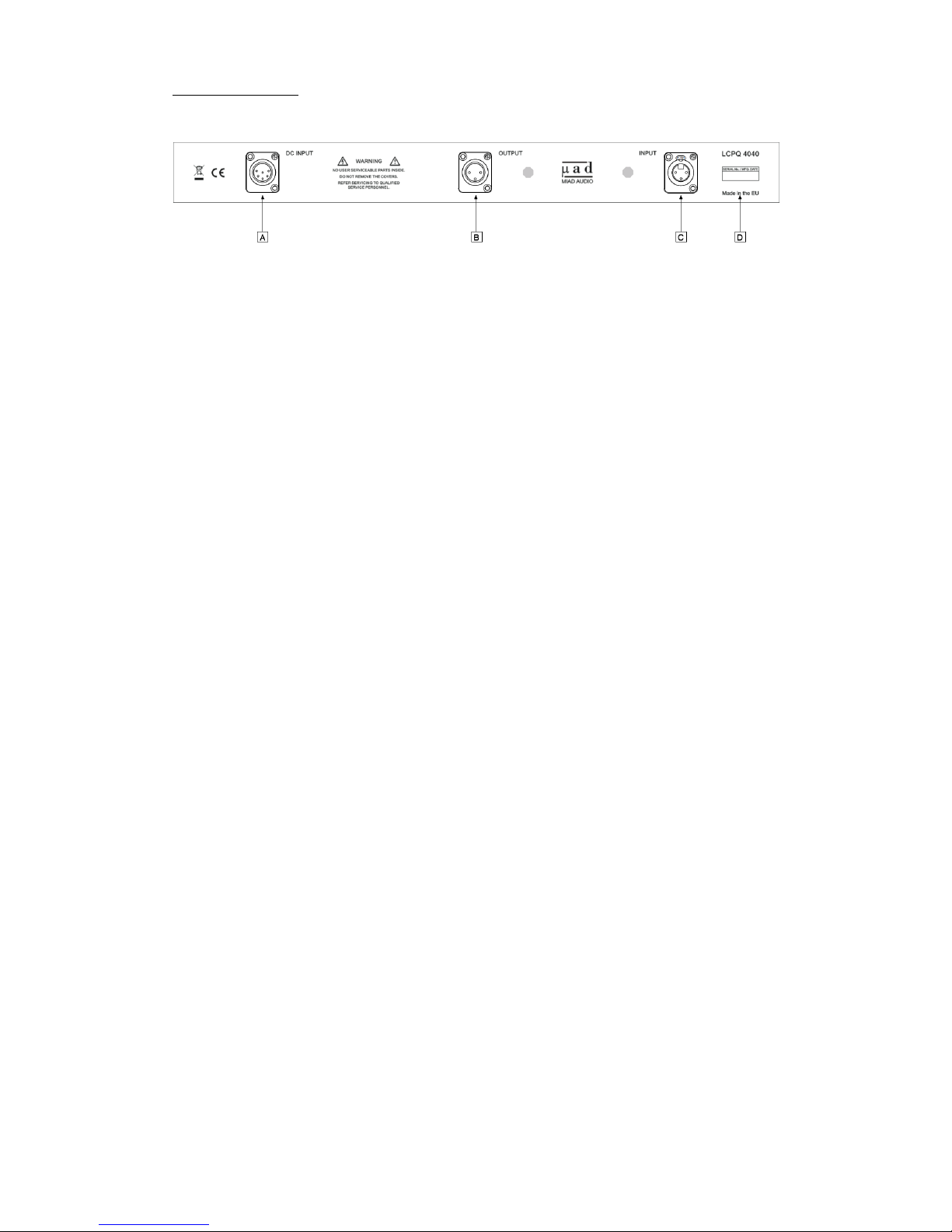
1.4!Rear!Panel!
!
!
!
!
!
A. 6-PIN DC POWER SUPPLY INPUT – This input allows interconnection
of the external supply (PS 230) required for the unit to operate. A 2-meter
power supply cable is supplied with every unit.
Pin out is as follows:
Pin 1= Chassis Ground
Pin 2= -28V (audio circuit)
Pin 3= +28V (audio circuit)
Pin 4= +24V (relay bypass system and bypass indicator)
Pin 5= 0V (reference for +24V)
Pin 6= 0V (reference for ±28V)
B. 3-PIN AUDIO OUTPUT – This is a transformer balanced XLR output
with the following pin configuration:
Pin 1 = Ground
Pin 2 = Hot (+)
Pin 3 = Cold (-)
C. 3-PIN AUDIO INPUT – This is a transformer balanced XLR input with
the following pin configuration:
Pin 1 = Ground
Pin 2 = Hot (+)
Pin 3 = Cold (-)
D. PRINT – Contains information regarding the model, the serial number and
the origin of the unit.

!
7!
2.0 PS!230!
!
2.1!Overview!
! !
The PS 230 is a 3-rail linear power supply capable of powering two LCPQ 4040 units,
housed in a robust enclosure.
The unit provides ±28V DC for the audio circuit and +24V DC for the relay bypass
system and the bypass indicator (LED). In order to cut the cost (and for the shake of
simplicity), a lot of audio euquipment use a common power rail for the audio circuit
and for other functions such as relays, LEDs, lamps, etc. However, it is a better
practice to use a dedicated power rail for all non-audio circuits. Therefore, the PS 230
has an additional +24V DC rail, which ensures that no unwanted noise (caused by the
relays and the bypass indicator) is added to the audio signal.
The PS 230 can be switched for 115V AC or 230V AC operation and the mains fuse
is accessible to the user from the rear side of the unit (in the IEC inlet).
2.2!Features!
! !
•High efficiency, low noise design
•Switchable 115V/ 230V AC
•Capable of powering two LCPQ 4040 units
•Separate power rails for the audio signal and the relay bypass system
•LED indicators for each power rail at the front of the unit
•High quality 6-pin Neutrik connectors
•Hand-built and hand-wired
•3-year limited warranty
!
8!
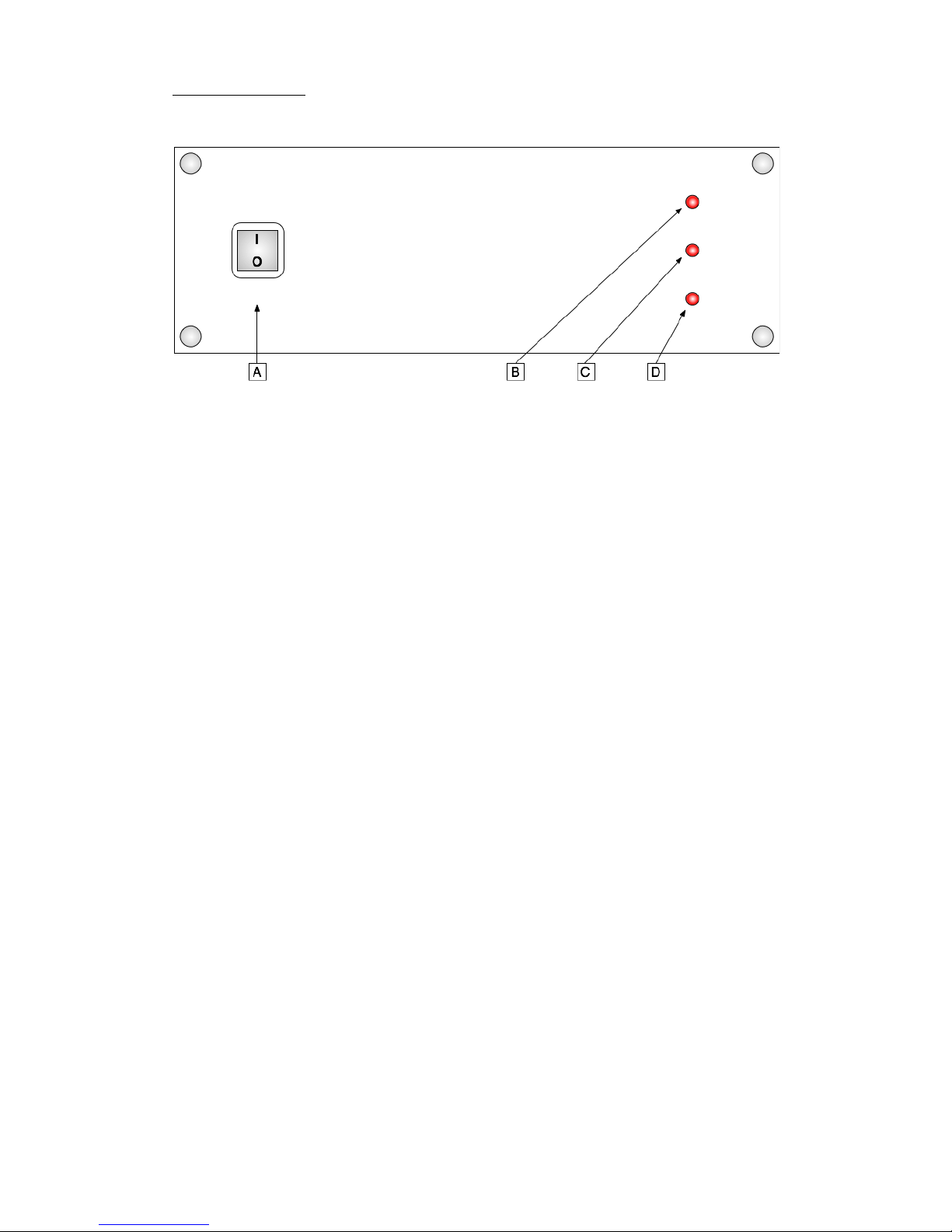
2.3!Front!Panel!
!
!
A. AC POWER SWITCH – This switch turns the unit ON and OFF. Make
sure you do not plug (or unplug) the 6-pin DC cable between the
power supply and the EQ unit while the unit (PS 230) is ON. Hot-
plugging (i.e connecting the DC cable while the unit is powered on)
may damage your equipment.
B. POWER INDICATION (-28V) – This LED allows visual confirmation of
the presence of -28V.
C. POWER INDICATION (+28V) – This LED allows visual confirmation of
the presence of +28V.
D. POWER INDICATION (+24V) – This LED allows visual confirmation of
the presence of +24V.

!
9!
2.4!Rear!Panel!
!
!
!
A. 6-PIN DC POWER SUPPLY OUTPUTS – This output allows
interconnection of the LCPQ 4040 unit. Up to two EQs can be connected
to the power supply.
Pin out is as follows:
Pin 1= Chassis Ground
Pin 2= -28V (audio circuit)
Pin 3= +28V (audio circuit)
Pin 4= +24V (relay bypass system and bypass indicator)
Pin 5= 0V (reference for +24V)
Pin 6= 0V (reference for ±28V)
B. PRINT – Contains information regarding the serial number and the
manufacturing date of the unit.
C. IEC MAINS INLET – Including the 115/230V AC switch and fuse. Make
sure that the AC voltage indicated on the IEC inlet is the same as the
mains in your country and that you use the correct fuse. An IEC mains
power cord is supplied with every unit.
! !
!
!
!
!

!
10!
3.0 Troubleshooting!
!
more contact information, check our website (www.miad.eu). Before contacting us,
please be prepared to describe in detail the exact problem that the unit is experiencing.
It is highly recommended that customers do not attempt to troubleshoot their own
units or have them repaired at unauthorized repair centers. Please note that any
modification to the existing product will void the warranty.
!
!
4.0 Specifications!
!
4.1!LCPQ!4040!Technical!Specifications!
Frequency Response: 20Hz - 20kHz, +0/ -0.3dB
THD+N: Less than 0.01%, +4dbu, 20Hz -22kHz, unity gain, 22kHz BW
Signal-to-Noise Ratio: <92dB (unweighted), re +4dbu, 22kHz BW, unity gain
Maximum Output Level: +21dbu, 20Hz -22kHz into 600 Ohms
Dynamic Range: 113dB re +21dBu, 22kHz BW
I/O Connectors: Transformer Balanced XLR (1.Chassis, 2.Signal +, 3. Signal -)
4.2!LCPQ!4040!Dimensions!
Unit!!!!!!Shipping!
Width: 482.6mm (19-inch rack) Width: 550mm
Depth: 300mm Depth: 450mm
Height: 43.7mm (1U rack) Height: 180mm
Weight: approx. 3kg Weight: approx. 4kg
!
4.3!PS!230!Technical!Specifications!
Input Voltage: 115V AC or 230V AC, 50/ 60Hz
Output Voltage: -28V DC, +28V DC, +24V DC
4.4!PS!230!Dimensions!
Unit!!!!!!Shipping!
Width: 230mm Width: 340mm
Depth: 170mm Depth: 240mm
Height: 80mm Height: 180mm
Weight: Unit approx. 2kg Weight: approx. 3k

!
11!
5.0 Appendix!
!
5.1!Warranty!Registration!
!
To be eligible for the three (3) year limited warranty, the original purchaser must
register the MIAD Audio product(s) within thirty (30) days of date of purchase.
Register online at www.miad.eu/ProductRegistration
!
!
5.2!Product!Warranty!!
!
During the first three (3) years from the date of the original purchase, this product is
warranted to be free from defects in materials and workmanship under normal use,
service and maintenance. This warranty is limited to failures during normal use,
which are due to defects in material or workmanship. If any defects are found in the
materials or workmanship, or if the product fails to function properly during the
applicable warranty period, MIAD Audio, at its option, will repair or replace the
product.
This warranty applies to the original purchaser and is subject to the following terms
and conditions:
1. The warranty only applies to MIAD Audio products purchased directly from
MIAD Audio or from authorised MIAD Audio dealers. The authorised dealers of
MIAD Audio products are listed online at www.miad.eu/Dealers
2. The warranty does not cover any of the following: damage caused by the user;
spillages or moisture; neglect, abuse or misuse, including but not limited to the
failure to use the MIAD Audio product for its normal purpose in accordance with
the manufacturer's instructions for usage, failure to properly maintain the MIAD
Audio product in accordance with the manufacturer's instructions, and/or the
failure to use the MIAD Audio product in accordance with the manufacturer's
specifications; use of product with incompatible or faulty equipment; unauthorised
modifications; repairs conducted by unauthorised persons or service centres; the
model and/or serial number being altered, removed or made illegible; damage
resulting from improper packing or mishandling by a shipper; accidents; acts of
God; Cosmetic defects, such as paint finish, and general wear and tear or any cause
beyond the control of MIAD Audio.
3. If the equipment requires warranty repair, return authorization must be obtained
from MIAD Audio prior to shipment. Equipment should not be shipped until return
authorization and proper shipping address is obtained from MIAD Audio.
4. Any products returned MIAD Audio for repair should be in their original
packaging and they should include: (1) complete description of the problem; (2)
name, address, phone number and e-mail address; (3) receipt of original purchase;
(4) power supply and all accessories and cables.

!
12!
5. MIAD Audio will not accept any warranty replacement without the original proof
of purchase of the MIAD Audio, and without the registration of the MIAD Audio
product. It is the original purchaser's responsibility to keep the original proof of
purchase safe at all times, as MIAD Audio is not obliged to provide a replacement
of the original proof of purchase, and to transfer that proof of purchase to any
subsequent owners of the MIAD Audio product.
6. The purchaser is responsible for the shipping costs to and from MIAD Audio.
MIAD Audio is not responsible for damage resulting from improper packing
and/or mishandling by a shipper.
7. MIAD Audio reserves the right to inspect any products that may be the subject of
any warranty claims before repair or replacement is carried out. Final
determination of warranty coverage lies solely with MIAD Audio.

!
13!
5.3!Block!Diagram!
!

!
14!
5.4!Frequency!Response!
!
Frequency Range: 20Hz to 20kHz / Magnitude Range: -1.0dB to +1.0dB
(All bands ‘ON’ at unity gain)
!
!
!
!
!
5.5!EQ!Response!Curves!
!
The graphs below demonstrate some of the measured response curves for each band.
BAND 1 BAND 2
Top Curve: Shelv. - Max. Boost @ 45Hz (20Hz – 40kHz)Top Curve: Low Q - Max. Boost @ 560Hz (20Hz – 40kHz)
Bottom Curve: Bell - Max. Cut @ 45Hz (20Hz – 40kHz)Bottom Curve: Hi. Q - Max. Cut @ 560Hz (20Hz – 40kHz)
BAND 3 BAND 4
Top Curve: Low Q - Max. Boost @ 3.3kHz (20Hz – 40kHz)Top Curve: Shelv.- Max. Boost @ 6.8kHz (20Hz – 40kHz)
Bottom Curve: Hi. Q - Max. Cut @ 3.3kHz (20Hz – 40kHz)Bottom Curve: Bell - Max.Cut @ 6.8kHz (20Hz – 40kHz)

!
15!
ARTIST _______________________________ PROJECT _______________________________ DATE __________________
TRACK ________________________ INSTRUMENT __________________________ ENGINEER _______________________
NOTES __________________________________________________________________________________________________________
LCPQ 4040 - RECALL SHEET
Table of contents
Popular Stereo Equalizer manuals by other brands

Behringer
Behringer MiniFBQ FBQ800 quick start guide

Altec Lansing
Altec Lansing 8751A SIGNAL PROCESSING manual

LA Audio Electronic
LA Audio Electronic EQX20 Specification sheet

PYLE Audio
PYLE Audio PLE730R owner's manual

Precision Power
Precision Power PAR-225 Operator's manual

Z Systems
Z Systems z-q2 Operation manual


