Mid-tech ARC 6000 User manual
ARC 6000 CONSOLE
USER GUIDE
PN: 98-05012

QUICK START REFERENCE
The following items should be checked before starting each days operation. The
BOLD TYPE designates the switch positions required to view the information
mentioned. (For detailed information, or if this is the initial setup for the machine, see
Chapter 2.)
1. Application Rate - APPLICATION RATE/OPERATE
2. Clear accumulators
A. Area Accumulators - There are two area accumulators that can be reset
individually. Select the desired area accumulator and hold down the INC/DEC
switch until the display reads zero.
1) FIELD AREA/DEC
2) TOTAL AREA/DEC
B. Volume Accumulator - TOTAL APPLIED/OPERATE/DEC
3. Load Volume
A. Full Load Volume - If you are starting with a new load, set the "Full Load
Value" by selecting PRODUCT VOL./OPERATE and holding the INC/DEC
switch up for at least three seconds.
B. Partial Load Volume - Select "Full Load Value" as described in 4.A above.
Then hold down on the INC/DEC switch until the display reads the actual
volume loaded into the tank.
QUICK SET UPREFERENCE
1. Perform the items found in the Quick Start Reference above plus the items below.
2. Select U.S./Metric Units - SPEED/OPERATE - Use INC/DEC switch to select.
A. INC to select Metrish
B. DEC to select U.S. and Metric
3. % Rate Change - % RATE/SET-UP
4. GSO Speed - SPEED/SET-UP
5. Test Speed - TEST SPEED/SET-UP or OPERATE
6. Field Area Alarm - FIELD AREA/SET-UP
7. Console Calibration Numbers
A. Distance Cal. # - DISTANCE/SET-UP
B. Flow meter Cal. # - TOTAL APPLIED/SET-UP
C. Boom Widths - IMPL. WIDTH/SET-UP - All booms OFF. Check each
individual boom section as it is displayed. All unused boom sections should be
set to zero.
8. Setting Hold/Close Response
A. Implement Status Off - TOTAL APPLIED/OPERATE - Hold INC/DEC
switch up. Will cycle between Hold and Close.
B. All Booms Off - IMPL. WIDTH/OPERATE - Hold INC/DEC switch up. Will
cycle between Hold and Close.

I98-05012
R3
ARC-6000
TABLE OF CONTENTS
TABLE OF CONTENTS I
LIST OF ILLUSTRATIONS III
REVISION LOG III
HOW TO USE THIS MANUAL IV
CHAPTER 1 SWITCHES AND CONTROLS 1-1
CONSOLE SWITCHES AND INDICATORS 1-1
DISPLAY SELECTOR SWITCH 1-2
DISPLAY SELECTOR FUNCTIONS - OPERATE MODE 1-2
DISPLAY SELECTOR FUNCTIONS - SETUP MODE 1-3
STATUS SWITCH 1-4
GROUND SPEED OVERRIDE SWITCH 1-5
CHAPTER 2 CALIBRATION 2-1
ENGLISH, METRIC, OR METRISH UNITS 2-1
SETTING APPLICATION RATES 2-2
SETTING THE % RATE CHANGE 2-3
SETTING BOOM WIDTHS 2-3
DISTANCE CALIBRATION - GROUND SPEED SENSOR 2-4
FLOW METER CALIBRATION 2-7
SETTING THE HOLD/CLOSE RESPONSE 2-10
SETTING THE TEST SPEED VALUE 2-11
SETTING THE GROUND SPEED OVERRIDE (GSO) VALUE 2-12
SETTING THE FIELD AREA ALARM 2-13
PRODUCT VOLUME (FULL LOAD VALUE) 2-13
CHAPTER 3 OPERATION 3-1
NORMAL START-UP AND OPERATION 3-1
CHANGING ACTIVE BOOM SECTIONS 3-2
CHANGING APPLICATION RATE 3-2
PRIMING THE MAIN PUMP AND BOOM 3-4
GROUND SPEED OVERRIDE 3-4
CHAPTER 4 MAINTENANCE 4-1
FLUSHING AND CLEANING 4-1
CONTROL CONSOLE 4-1
GROUND SPEED SENSOR 4-2
FLOW SENSOR 4-2
FLOW CONTROL VALVE 4-3
WIRING HARNESS 4-3
CHAPTER 5 TROUBLE SHOOTING - ERROR MESSAGES 5-1
CHAPTER 6 EMERGENCY OPERATION 6-1
GROUND SPEED SENSOR FAILURE 6-1
FLOW CONTROL VALVE FAILURE 6-2
FLOWMETER FAILURE 6-4
APPENDIX A - SYSTEM DIAGRAMS A-1
APPENDIX B - SYSTEM OVERVIEW B-1
HOW THE ARC CONTROLS APPLICATION RATE B-2
ARC SYSTEM COMPONENTS B-2
APPENDIX C - GLOSSARY/TABLES C-1
GLOSSARY C-2
USEFUL FORMULAS C-6
ENGLISH/METRIC CONVERSION C-6
MISCELLANEOUS NOTES C-8
CALIBRATION NUMBERS C-8
MID-TECH, Auto-Range, & TASC are all registered trademarks of Midwest Technologies, Inc.

II
ARC-6000
98-05012
R3
This page left blank intentionally

III 98-05012
R3
ARC-6000
FIG. 1-1. ARC CONSOLE - SWITCHES AND INDICATORS 1-1
FIG. 1-2. DISPLAY SELECTOR FUNCTIONS - OPERATE MODE 1-2
FIG. 1-3. DISPLAY SELECTOR FUNCTIONS - SET-UPMODE 1-3
FIG. 3-1. BOOM SECTION SWITCHES 3-2
FIG. 3-2. CHANGING APP. RATE “O NTHE GO”. 3-3
FIG. A 1. ARC FLOW CONTROL - WIRING DIAGRAM A-2
FIG. A 2. ARC FLOW CONTROL - PLUMBING DIAGRAM A-3
FIG. A 3. SERVICE FORM A-4
FIG. B-1 ARC SYSTEM DATA FLOW B-2
FIG. B-2. ARC 6000 CONSOLE B-3
FIG. B-4. FLOW METER B-4
FIG. B-3. GROUND SPEED RADAR B-4
FIG. B-5. FLOW CONTROL VALVE B-4
FIG. B-6. BOOM CONTROL SWITCHBOX B-5
Revision Reason SW Ver.
97108 New Manual 1.31
98250 New Format 1.31
2 Updated Graphics 1.31
& Format
3 Updated Graphics 1.31
& Format
Revision Log
List of Illustrations

IV
ARC-6000
98-05012
R3
This page left blank intentionally

V98-05012
R3
ARC-6000
Mid-TMid-Tech
HOW TO USE THIS MANUAL
This manual is designed to provide you with
the basic information needed to set up and
operate the MID-TECH®Automatic Rate Control (ARC)
spraying system. Actual procedures may vary somewhat,
depending on the configuration of your system.
When you see "Mitch", he is pointing out special information
that you should be aware of, regarding safety, preventing
console damage, an easier way to perform an operation, etc..
Below is a listing of the chapters in this manual, along with a
brief description of the information found in each chapter.
Chapter 1 - Switches and Controls - Lists each control switch,
on the face of the console, and gives a brief description of its
use.
Chapter 2 - Calibration and Setup - Takes you, step by step,
through the calibration of each sensor providing input to the
console, and the entering of other information the console
needs to perform the functions you require.
Chapter 3 - Operation - Briefly describes how to initiate the
spraying operation.
Chapter 4 - Trouble shooting - Lists possible causes and
remedies for the error codes that appear on the ARC display
if the console detects a problem.
Chapter 5 - Maintenance - Describes the basic maintenance
needed to keep your system operating at peak performance.
Chapter 6 - Emergency Operations - Suggests ways to operate,
under reduced accuracy, in the event of a major fault.
Appendix A - Sample system wiring and plumbing diagrams.
Appendix B - System Overview - Describes the major compo-
nents of the ARC system and their individual functions in
application control.
Appendix C - Glossary/Tables
Back Cover - Quick Start/Quick Set Up Guides

VI
ARC-6000
98-05012
R3
This page left blank intentionally
1-1 98-05012
R3
ARC-6000
This chapter shows the location of each switch
and indicator found on the ARC control console
and discusses its function in both the Operate
and Setup modes. (Further information can be found
on pages shown in parenthesis.)
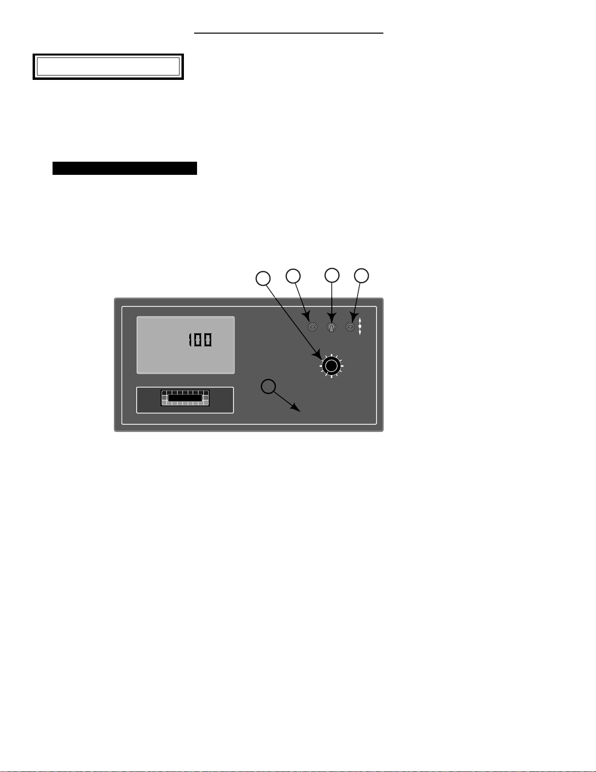
Console Switches and Indicators
POWER SWITCH
The Power switch (See #1 in Fig. 1-1) controls
the power to the console. Always turn the
Power switch “OFF”when not in use. This
protects against accidental operation of the control
system and unnecessary current drain on the vehicle
battery.
Don’t
worry about
the console
losing the
set-up
information
with the
power
turned off.
The ARC
Control
Console has
a nonvola-
tile memory
that doesn’t require constant power to hold it’s
information.
MODE SELECTOR SWITCH
The Mode Selector switch (See #2 in Fig. 1-1) is used
to switch between the OPERATE and SETUP modes
of the Control Console. When applying product, this
switch must be in the “OPERATE”position. The
“SET-UP”position is used for entering information
into the console. In the SETUP Mode an “Err”
message appears if a position is selected which can not
be programmed.
%Rate
DISPLAY SELECTOR
Speed
Field Area Impl.Width
Distance
Test
Speed
Prime
Total Applied
Application Rate
OFF SET- UP DEC.
ON OPERATE INC.
Scan
Total Area
Product Vol.
ARC-6000
Automatic
Rate Controller
MID-TECH
¨
MIDWEST TECHNOLOGIES, INC.
123456789
BOOMS
.
-Ac
Flow
RATE
Gal./
3
12
4
5
Chapter 1 Switches and Controls
Fig. 1-1. ARC Console -
Switches and Indicators

1-2
ARC-6000
98-05012
R3
OFF SET- UP DEC.
ON OPERATE INC.
ARC-6000
Automatic
Rate Controller
MID-TECH
MIDWEST TECHNOLOGIES, INC.
123456789
%Rate
DISPLAY SELECTOR
Speed
Field Area Impl.Width
Distance
Test
Speed
Prime
Total Applied
Application Rate
Scan
Total Area
Product Vol.
BOOMS
.
-Ac
Flow
RATE
Gal./
123456789
%Rate
DISPLAY SELECTOR
Speed
Field Area Impl.Width
Distance
Test
Speed
Prime
Total Applied
Application Rate
Scan
Total Area
Product Vol.
BOOMS
¨
%Rate
DISPLAY SELECTOR
Speed
Field Area Impl.Width
Distance
Test
Speed
Prime
Total Applied
Application Rate
Scan
Total Area
Product Vol.
OFF SET- UP
ON OPERATE
SET- UP
OPERATE
INC / DEC SWITCH
The Increase/Decrease (INC/DEC) switch (See #3 in
Fig. 1-1) is used, in both the OPERATE and SETUP
modes, to change the values appearing in the display.
Boom Section “ON/OFF” Indicators
The boom section On/Off indicators (See #5 in Fig. 1-
1.) indicate which boom sections are selected by the
operator. When a boom is been selected, its indicator
lamp is lit. Boom section number 1 is usually the one
to the left of the sprayer. There are a maximum of nine
boom sections available.
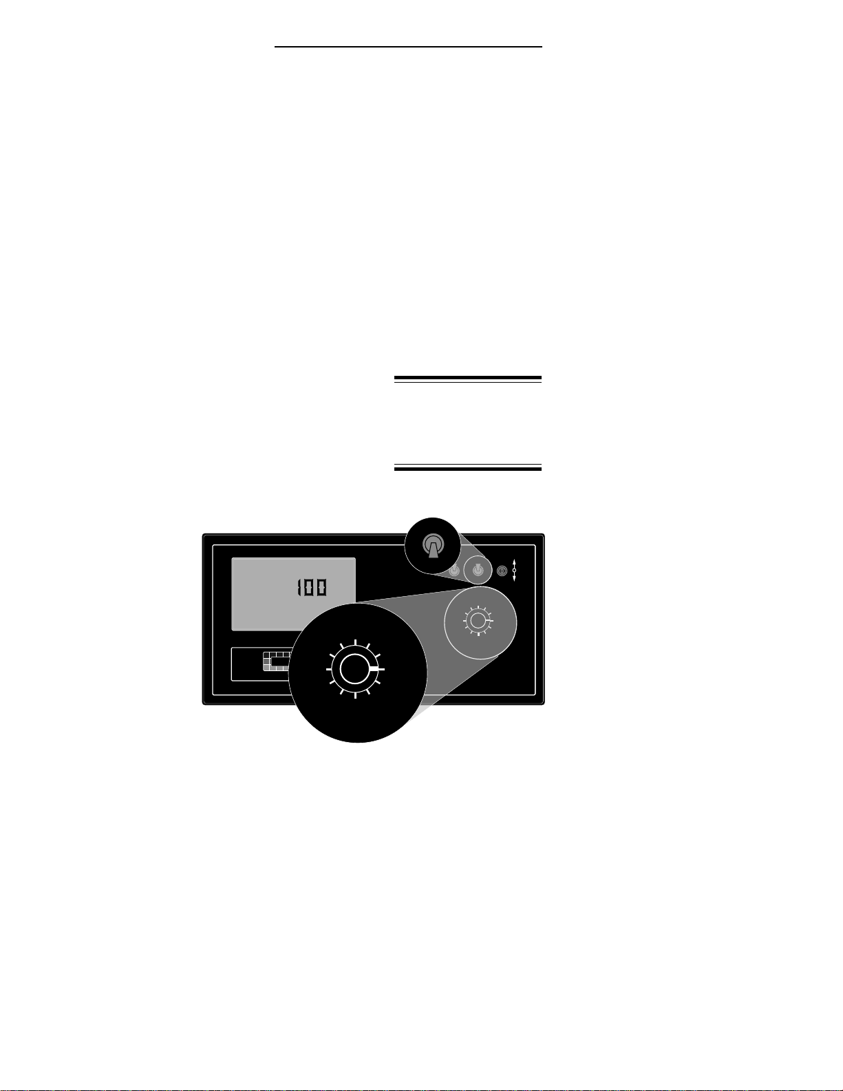
Display Selector Switch
The Display Selector (See #4, Fig. 1-1) is used to
choose which of the various console functions is to be
displayed on the screen and available for adjustment
by the operator.
Display Selector Functions - Operate Mode
Speed: The current
vehicle speed.
Field Area:
Accumulated Area.
(Pg. 3-1)*
Total Area:
Accumulated Area.
(Pg. 3-1)*
Product Vol:
Amount of product
aboard the sprayer.
(Pg. 2-14)**
% Rate: The percent by which the programmed
application rate, at which the product is being
applied, is changed with each activation of the INC/
DEC switch. (Pg. 2-3)***
Fig. 1-2. Display Selector
Functions - Operate Mode
1-3 98-05012
R3
ARC-6000
Application Rate: The desired application rate. (Pg.
2-2)** Once application has started, and metered
discharge is established, the actual measured
application rate is displayed here. (Also used to set
the control valve to manual control.) (Pg. 6-4)
Total Applied: The total volume of product applied,
as measured by the flow meter.*
Impl. Width: The active boom width, (Total width of
all boom sections turned “ON”).
Distance: The accumulated distance.
Prime: This position is used to lock the control valve
open during product pump priming. (Pg. 3-4)
Test Speed: The speed the console uses for stationary
tests of the sprayer. (Pg. 2-12)**
Scan: The display scans SPEED, FIELD AREA,
PRODUCT VOLUME, APPLICATION RATE,
and TOTAL APPLIED, holding at each position
for approximately two seconds before automati-
cally cycling to the next.
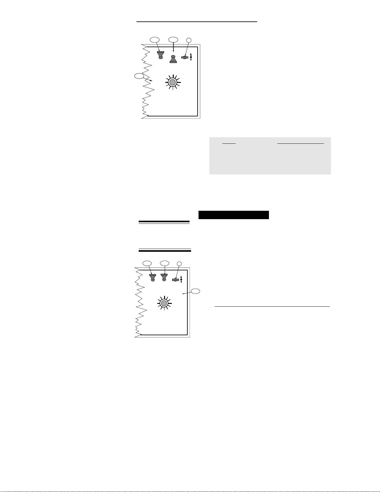
Display Selector Functions - Setup Mode
Speed: Ground
Speed Override
(GSO) Value.
(Pg. 2-13)**
Field Area: Select
area alarm. The
display flashes
and the console
beeps each time
a selected
increment is
reached. The
display reacts for about three seconds and then
stops until the next increment is reached. (Set to
zero to disable.) (Pg. 2-14)**
Total Area: Err, No function in the SETUP mode.
* Totals can be reset in this
mode.
** Values are programmable
in this mode.
*** Values changeable by a %
increase or decrease.
OFF SET- UP DEC.
ON OPERATE INC.
ARC-6000
Automatic
Rate Controller
MID-TECH
MIDWEST TECHNOLOGIES, INC.
123456789
%Rate
DISPLAY SELECTOR
Speed
Field Area Impl.Width
Distance
Test
Speed
Prime
Total Applied
Application Rate
Scan
Total Area
Product Vol.
BOOMS
.
-Ac
Flow
RATE
Gal./
12345678
%Rate
DISPLAY SELECTOR
Speed
Field Area Impl.Width
Distance
Test
Speed
Prime
Total Applied
Application Rate
Scan
Total Area
Product Vol.
BOOMS
¨
%Rate
DISPLAY SELECTOR
Speed
Field Area Impl.Width
Distance
Test
Speed
Prime
Total Applied
Application Rate
Scan
Total Area
Product Vol.
OFF SET- UP
ON OPERATE
SET- UP
OPERATE
Fig. 1-3. Display Selector
Functions - Set-Up Mode

1-4
ARC-6000
98-05012
R3
Product Volume: Use the INC/DEC switch to set the
full load value of the vehicle. (Pg. 2-14)**
% Rate: The percent by which the programmed
application rate can be changed with each activa-
tion of the INC/DEC switch when application is
underway. (Pg. 2-3)**
Application Rate: ERR, No function in SETUP
mode.
Total Applied: This is the flow meter calibration
number. (Pg. 2-8)**
Width: Individual boom section widths. The display
cycles through the individual boom sections in
order, unless a particular boom switch is activated
and the boom master switch is ON. (Pg. 2-3)**
Distance: Distance Calibration Number. (Pg. 2-4)**
Prime: Reads Pump L STnrd - Cannot be changed.
Test Speed: The current Test Speed (Pg. 2-12).**
Status Switch
An external “Implement Status”input can be
used to override the ARC control. The input
must present a positive voltage (+12.0 VDC)
on the green (or white) wire of the Boom Interface
Cable. As long as this condition is present, the
Control Console operates normally. If the voltage is
interrupted, the Control Console automatically stops
applying. At the same time, the Control Console will
either "HOLD" or "CLOSE" the Control Valve,
depending on the response selected by the operator.
(See Page 2-11).
This feature allows the operator to control the
operation of the control valve through the normal
operation of the vehicle. The Status input can be
used to sense the "ON"/"OFF" condition of the main
vehicle pump switch, a separate Master Switch, or, an
external switch monitoring an implement "UP"/
"DOWN" condition.
* Totals can be reset in this
mode.
** Values are programmable
in this mode.
*** Values changeable by a %
increase or decrease.

1-5 98-05012
R3
ARC-6000
Ground Speed Override Switch
If your ARC system includes an optional MID-
TECH®Boom Control Switch Box, the Ground
Speed Override (GSO) switch is already installed.
An optional, externally mounted, GSO switch can be
used to temporarily operate the sprayer using a pre-
selected, "GSO”, minimum speed rather than the
actual vehicle ground speed. The override feature is
used to reach the application rate quickly when
starting the vehicle from a complete stop or to
maintain an adequate spray pattern when the vehicle
is moving at very low ground speeds. It can also be
used to allow the operator to flush or empty the tank
from the cab, with the vehicle stopped.
The Control Console operates normally as long as the
GSO switch condition is open (OFF). Whenever the
switch is closed (ON) and the actual ground speed is
less than the "GSO Speed", the Control Console
automatically uses the "GSO Speed" value to control
application rate. As soon as the switch reverts to its
normally open (OFF) condition, or the actual ground
speed increases above the preset "GSO Speed", the
Control Console will adjust the application rate based
on the actual ground speed.
CAUTION: Controlling application rates based on a
"GSO Speed" is not as accurate as using the actual
ground speed. When Ground Speed Override is being
used and the true ground speed is less than the
"Ground Speed Override”speed, the console sounds
an alarm and the display flashes a "Too Slow"
message to warn the operator of possible mis-
application.
Mid-Tech
Fig. B-6, in Appendix B,
shows a “Boom Control
Switch Box” which incorpo-
rates the Implement Status
Switch and the GSO function
into one switch. The “OFF”
position provides a Status
Switch “OFF” condition,
“AUTO” furnishes Status
Switch ON, and “GSO”
activates the GSO function.
Other methods of controlling
these functions are also
available. This switchbox also
includes an individual ON/
OFF switch for each boom
section.

1-6
ARC-6000
98-05012
R3
This page left blank intentionally

2-1 98-05012
R3
ARC-6000
Chapter2Calibration
NOTE: PLEASE READ THROUGH THE FOLLOW-
ING SECTIONS COMPLETELY BEFORE YOU
BEGIN CALIBRATION!
The Control Console must be calibrated and pro-
grammed with certain information before it can be
used. First, the specific details of your applicator
(i.e. Application Rates, Boom Widths, Test Speed, etc.)
are entered. Next, the flowmeter and ground speed
sensors are both calibrated. The calibration and set up
procedures are not difficult, however, they must be
followed precisely in order to get the maximum possible
accuracy out of the system.
English,Metric,orMetrishUnits
The Control Console is capable of displaying
three different units of measure, US, Metric
and Metrish. Metrish is the same as Metric, except
area is measured in Acres.
UNITS FOR EACH DISPLAY SELECTOR SWITCH POSITION
Mid-Tech
POSITION US METRIC METRISH
Speed Miles/Hour (mph) Kilometers/Hour (kph) Kilometers/Hour (kph)
Field Area Acres (acre) Hectares (ha) Acres (acre)
Total Area Acres (acre) Hectares (ha) Acres (acre)
Product Vol. US Gallons (gal.) Liters (l) Liters (l)
Appl. RateUS Gallons/acre (gpa) Liters/Hectare (l/ha) Liters/Acre (l/acre)
Total Applied US Gallons (gal.) Liters (l) Liters (l)
Impl. Width Inches - Feet (in., ft.) Meters (m) Meters (m)
Distance Feet - Miles (ft.-miles)* Meters - Kilometers (m-km)* Meters - Kilometers (m-km)*
Test Speed Miles/Hour (mph) Kilometers/Hour (kph) Kilometers/Hour (kph)
* No units displayed after roll over of feet to miles or meters to kilometers
2-2
ARC-6000
98-05012
R3
Setting the APPLICA-
TION RATE to 0.0 will
turn off the flow
control function.
DISPLAY SELECTOR
Speed
Field Area Impl. Width
Distance
Test
Speed
Prime
Total Applied
Application Rate
OFF SET- UP DEC.
ON OPERATE INC.
Scan
Product Vol.
Total Area
BOOMS
123456789
% Rate
B
A-1 A-2
A-3
DISPLAY SELECTOR
Speed
Field Area Impl. Width
Distance
Test
Speed
Prime
Total Applied
Application Rate
OFF SET- UP DEC.
ON OPERATE INC.
Scan
Product Vol.
Total Area
BOOMS
123456789
% Rate
B
A-1 A-2
A-3
CHANGING UNITS
A. Set the console switches to the following positions:
1. Power “ON”
2. Mode Selector “OPERATE”
3. Display Selector “SPEED”
The display shows the current speed units.
B. Using the INC/DEC Switch, select the measuring
system desired (See following chart). The INC/DEC
Switch must be held for approximately 5 sec. before
the change occurs.
Units INC./DEC. Switch
English to Metric “DOWN”
Metric to English “DOWN”
English to Metrish “UP”
Metrish to English “DOWN”
NOTE: Metric to Metrish is not available. Change to
English first and then to Metrish.
SettingApplicationRates
The ARC 6000 system is designed to maintain a
constant, pre-selected application rate. In order for
the Control Console to do this, the operator must
enter the desired application rate. To set the desired
applicationrate:
A. Set the console switches to the following positions:
1. Power “ON”
2. Mode Selector “OPERATE”
(Application Rate is set in the Operate Mode!!!)
3. Display Selector “APPLICATION RATE”
The display shows the current application rate.
B. Using the INC/DEC switch, set the desired rate.

2-3 98-05012
R3
ARC-6000
MASTER
ON
OFF
MI
B
F
DISPLAY SELECTOR
Speed
Field Area Impl. Width
Distance
Test
Speed
Prime
Total Applied
Application Rate
OFF SET- UP DEC.
ON
OPERATE INC.
Scan
Product Vol.
Total Area
BOOMS
123456789
% Rate
B
A-1 A-2
A-3
DISPLAY SELECTOR
Speed
Field Area Impl. Width
Distance
Test
Speed
Prime
Total Applied
Application Rate
OFF SET- UP DEC.
ON OPERATE INC.
Scan
Product Vol.
Total Area
BOOMS
123456789
% Rate
C, D, E
A-1 A-2
A-3
F
Setting the % Rate Change
This feature allows the operator to change the
application rate “ON THE GO”with a simple
actuation of the INC/DEC switch. The amount of
change each switch actuation makes is proportional to the
value programmed into this position, (e.g. 20 =20% change
in the target rate). For example, with the liquid application
rate set to 10.0 gallons per acre, a single actuation of the
INC switch causes the system to control flow at the rate of
12.0 gallons per acre (10.0 + 20% = 12.0). To set the
desired % Rate Change value:
A. Set the console switches to the following positions:
1. Power “ON”
2. Mode Selector “SETUP
3. Display Selector “% RATE”
The display shows the current % change value.
B. Using the INC/DEC switch, set this number to the
desired % change value.
SettingBoomWidths
TheMIDWESTTECHNOLOGIESControlConsole
is designed to automatically compensate for
changes in the swath width, caused by turning
boom sections on or off. To accurately respond to
changes in swath width, the console must know the size
of each boom section. To set the desired boom section
widths:
A. Set the Console to the following positions;
1. Power “ON”
2. Mode Selector “SET- UP”
3. Display Selector “IMPL.WIDTH”
B. All Boom Switches (or Master Switch) “OFF”
The display cycles through each boom position (1
through 9) and displays its current width in inches.

2-4
ARC-6000
98-05012
R3
RECORD THESE CALIBRATION NUMBERS ON LAST PAGE OF MANUAL.
C. As each boom position appears on the display, use
the INC/DEC Switch to set the display to the number
of inches covered by that boom. Repeat for each
section.
D. Set all unused boom sections to a width of zero “ 0”
inches. This insures that accidentally turning a boom
switch “ON”doesn’t affect the control console.
E. Finally, let the boom width display cycle through the
boom sections until it shows “Boom C”. When the
“ C” width is displayed, set it to the normal operating
width of the entire sprayer, in inches, using the INC/
DEC switch.
F. The boom width is now set. Turn all booms “ON”and
return to the OPERATE Mode, the new total boom
width will be displayed in feet. If this does not agree
with your total applicator width, check the individual
boom widths, ( steps A, B and C).
DistanceCalibration-GroundSpeedSensor
GENERAL CONSIDERATIONS AND INITIAL CALIBRATION
NUMBERS
The Control Console must be calibrated to the
ground speed sensor installed to ensure accurate
application rates. The procedure involves physi-
cally measuring an accurate distance along a road or field,
driving the vehicle through that distance, mathematically
comparing the distance computed by the control console
to the actual measured distance, and making any neces-
sary adjustments to the distance calibration number.
Follow the recommended procedure below to ensure
accuracy of operation.Follow the recommended proce-
dure below to ensure accuracy of operation.
The distance calibration should be checked periodically to
maintain its accuracy. A calibration test is especially
important if the sensor mounting has become loose or has
been repositioned (Radar Sensor), or if the tires have been
changed (Wheel and Speedometer Sensor).
Boom widths are
entered in inches in the
US system. For
example; for a liquid
boom with 7 nozzles on
30" spacings, enter 210
for that boom. There is
no need to convert to
feet, the control
console does that
automatically when it is
switched back to the
Operate Mode. (In
metricand metrish,all
widths are entered in
meters.)
2-5 98-05012
R3
ARC-6000
Use the following initial calibration numbers.
MID-TECH®COMPACTRADAR-780
Dj RADAR - 1000
WHEEL SENSOR - 3500
SPEEDOMETERSENSOR-3500
To view and adjust the speed calibration number:
A. Set the Control Console switches to the following
settings:
1. Power “ON”
2. Mode Selector “SETUP”
3. Display Selector “DISTANCE”
The display shows the distance calibration value.
B. Use the INC/DEC switch to select the initial distance
calibration number suggested. You can now perform
the distance calibration procedure.
DISTANCE CALIBRATION PROCEDURE
The following procedure is recommended by MIDWEST
TECHNOLOGIES for establishing an accurate distance
calibration. NOTE: All boom switches should remain
“OFF”during the entire procedure.
A. Fill the vehicle 1/2 full of material (unless it is a pull
type unit with the speed sensor mounted on the tow
vehicle), to approximate actual load conditions. This
minimizes the effect on the radar mounting angle or
actual working diameter of the tires as the load
empties.
B. Measure a known distance of 400 ft. or more in a field
or roadway (preferably in terrain similar to that being
treated). Select an easy place in which to maneuver
the vehicle. A longer distance, allows a more accurate
test to be performed.
C. Record the current Distance Cal. #.
1. Turn the Display Selector to the “DISTANCE”
position.
DISPLAY SELECTOR
Speed
Field Area Impl. Width
Distance
Test
Speed
Prime
Total Applied
Application Rate
OFF SET- UP DEC.
ON
OPERATE INC.
Scan
Product Vol.
Total Area
BOOMS
123456789
% Rate
B
A-1 A-2
A-3
2-6
ARC-6000
98-05012
R3
RECORD THIS CALIBRATION NUMBER ON LAST PAGE OF MANUAL.
2. Set Mode Select switch to the “SET- UP”mode.
The console displays the current Distance
Calibration Number. Record this number for future
reference. As an example, assume this number is
1000.
D. Drive the vehicle to the starting point of the mea-
sured distance and stop.
E. Zero out the Distance Accumulator
1. Return the Mode Select switch to the “OPERATE”
position.
2. Reset the distance to zero using the DEC. switch.
F. Drive the vehicle to the other end of the measured
distance at a speed of between five and ten miles per
hour. Distance measurements will accumulate on the
display.
G. Stop the vehicle at the measured distance end marker.
Compare the indicated distance to the actual Mea-
sured distance, to determine how much correction is
necessary. For example: if the indicated distance is
396 Ft. after driving over a 400 foot range, the error in
the distance calibration is 1.0%.
H. Calculate the new Distance Calibration Number using
the following formula:
Example: (400 / 396) x 1000 = 1010, the New DC#
NOTE: The same calibrations are used, regardless of
the type of distance sensor .
J. Enter the corrected Cal. #.
1. Select "SETUP" mode.
2. Use the "INC/DEC" switch to enter the new
calibration number (See page 2-5).
3. Switch back to the "OPERATE" mode. The
distance accumulator should now agree with the
measured distance that you traveled. If it doesn't ,
recheck your calculations.
DISPLAY SELECTOR
Speed
Field Area Impl. Width
Distance
Test
Speed
Prime
Total Applied
Application Rate
OFF SET- UP DEC.
ON
OPERATE INC.
Scan
Product Vol.
Total Area
BOOMS
123456789
% Rate
E-1
C-2
C-1
E-2
DISPLAY SELECTOR
Speed
Field Area Impl. Width
Distance
Test
Speed
Prime
Total Applied
Application Rate
OFF SET- UP DEC.
ON
OPERATE INC.
Scan
Product Vol.
Total Area
BOOMS
123456789
% Rate
J-1 J-3 J-2
(Measureddistance/Indicateddistance)xOldDC#=NewDC#
Table of contents


