manuals.online logo
Brands
  1. Home
  2. •
  3. Brands
  4. •
  5. Middleby Marshall
  6. •
  7. Convection Oven
  8. •
  9. Middleby Marshall PS360-U Operation manual

Middleby Marshall PS360-U Operation manual

ENGLISH
page 1
1
DANSK
side 25
Middleby Cooking Systems Group  1400 Toastmaster Drive  Elgin, L 60120  USA  (847)741-3300  FAX (847)741-4406
© 2001 Middleby Marshall, Inc.
is a registered trademark of Middleby Marshall, Inc. All rights reserved.
PS300 Series Gas and Electric Ovens
PS300 Series
Gas and Electric (Europe)
ENGLISH/Danish
P/N 46486
Rev B  V1  7/01
Models:
 PS360-U, PS360-L Gas
 PS360-U, PS360-L Elec ric
 PS360WB-U, PS360WB-L Gas
Combinations:
 Single Oven
 Double Oven (Two-S ack)
Single Oven Double Oven
PS360 PS360WB PS360 PS360WB
Rated Heat Input 40kW 50kW 2x40kW 2x50kW
Gas Ovens
Rated Heat Input 26kW -- 2x26kW --
Electric Ovens
Heating Zones 1 controlled heat zone 2 controlled heat zones
OWNER'S OPERATING AND
INSTALLATION MANUAL
for European export ovens
2
ENGLISH
Middleby Cooking Systems Group  1400 Toastmaster Drive  Elgin, IL 60120  USA  (847)741-3300  FAX (847)741-4406
24-Hour Service Hotline: 1-(800)-238-8444
www.middleby.com
NOTICE:
This Owner's Operating and Insta ation Manua shou d be given to the user. The operator of the oven shou d
be fami iar with the functions and operation of the oven.
This manua must be kept in a prominent, easi y reachab e ocation near the oven.
Gas ovens are designed for use with EITHER natura gas OR iquid propane gas, as specified on the seria p ate.
Where permitted by oca and nationa codes, the oven can be converted from natura gas to propane operation,
or from propane to natura gas operation. This conversion is described in the Installation section of this Manua .
The conversion requires the insta ation of the appropriate Midd eby Marsha Gas Conversion Kit.
It is suggested to obtain a service contract with a Midd eby Marsha Authorized Service Agent.
WARNING
POST, IN A PROMINENT LOCATION, THE EMERGENCY TELEPHONE NUMBER OF YOUR LOCAL GAS
SUPPLIER AND INSTRUCTIONS TO BE FOLLOWED IN THE EVENT YOU SMELL GAS.
Instructions to be followed in the event the user smells gas shall be obtained by consulting the local gas
supplier If the smell of gas is detected, immediately call the emergency phone number of your local Gas
Company They will have personnel and provisions available to correct the problem
FOR YOUR SAFETY
Do not store or use gasoline or ot er flammable vapors or liquids in t e vicinity of
t is or any ot er appliance.
WARNING:
Improper installation, adjustment, alteration, service or maintenance
can cause property damage, injury or death. Read the installation,
operating and maintenance instructions thoroughly before installing
or servicing this equipment.
NOTICE: CONTACT YOUR MIDDLEBY MARSHALL AUTHORIZED SERVICE AGENT TO PERFORM MAINTENANCE
AND REPAIRS AN AUTHORIZED SERVICE AGENCY DIRECTORY IS SUPPLIED WITH YOUR OVEN
NOTICE: Using any parts other than genuine Middleby Marshall factory manufactured parts relieves the manufacturer of
all warranty and liability
NOTICE: Middleby Marshall (Manufacturer) reserves the right to change specifications at any time
NOTICE: The equipment warranty is not valid unless the oven is installed, started and demonstrated under the supervision
of a factory certified installer
IMPORTANT
An electrical wiring diagram for t e oven is located inside t e mac inery
compartment.
IMPORTANT
It is t e customer's responsibility to report any concealed or non-concealed damage
to t e freig t company. Retain all s ipping materials until it is certain t at t e
equipment as not suffered concealed s ipping damage.
Retain This Manual For Future Reference
3
ENGLISH
SECTION 1 - DESCRIPTION ................................................... 4
I. OVEN USES ............................................................. 4
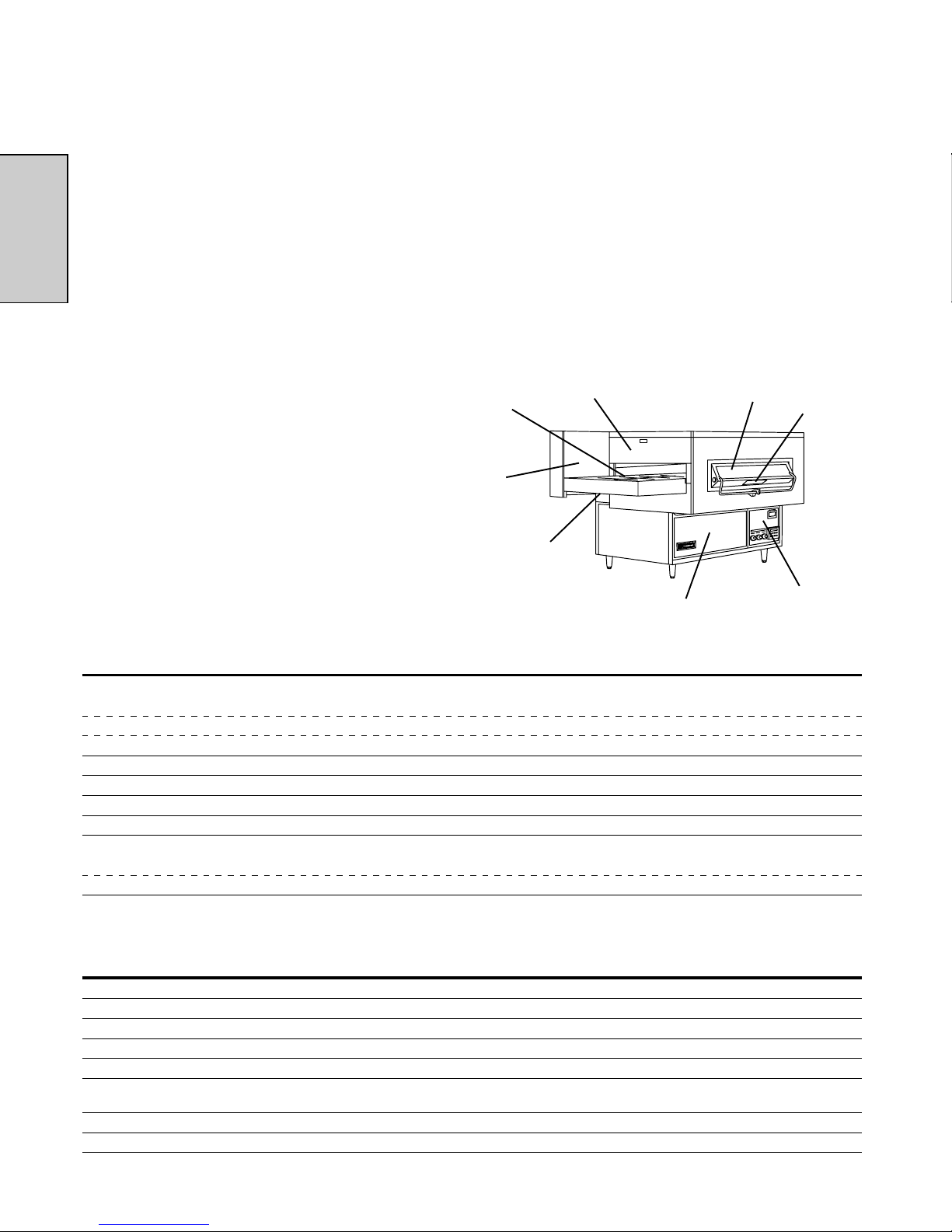
II. OVEN COMPONENTS ............................................. 4
A. Crumb Pans ..................................................... 4
B. Conveyor Drive Motor ....................................... 4
C. Conveyor ........................................................... 4
D. End P ugs ......................................................... 4
E. Seria P ate ....................................................... 4
F. Window ............................................................. 4
G. Machinery Compartment Access Pane .......... 4
H. Contro Compartment Access Pane .............. 4
I. Contro Pane .................................................... 4
J. Eyebrows .......................................................... 4
K. Conveyor End Stop ........................................... 4
L. Gas Burner or Heating E ements .................... 4
M. B owers............................................................. 4
N. Air Fingers ........................................................ 4
III. OVEN SPECIFICATIONS ......................................... 4
A. Dimensions ...................................................... 4
B. Genera Specifications ..................................... 4
C. E ectrica Specifications ................................... 5
D. Gas Orifice and Pressure Specifications........ 5
SECTION 2 - INSTALLATION .................................................. 5
I. INSTALLATION KIT .................................................. 6
II. VENTILATION SYSTEM ........................................... 7
A. Requirements .................................................. 7
B. Recommendations .......................................... 7
C. Other Venti ation Concerns .............................. 7
III. ASSEMBLY ............................................................... 8
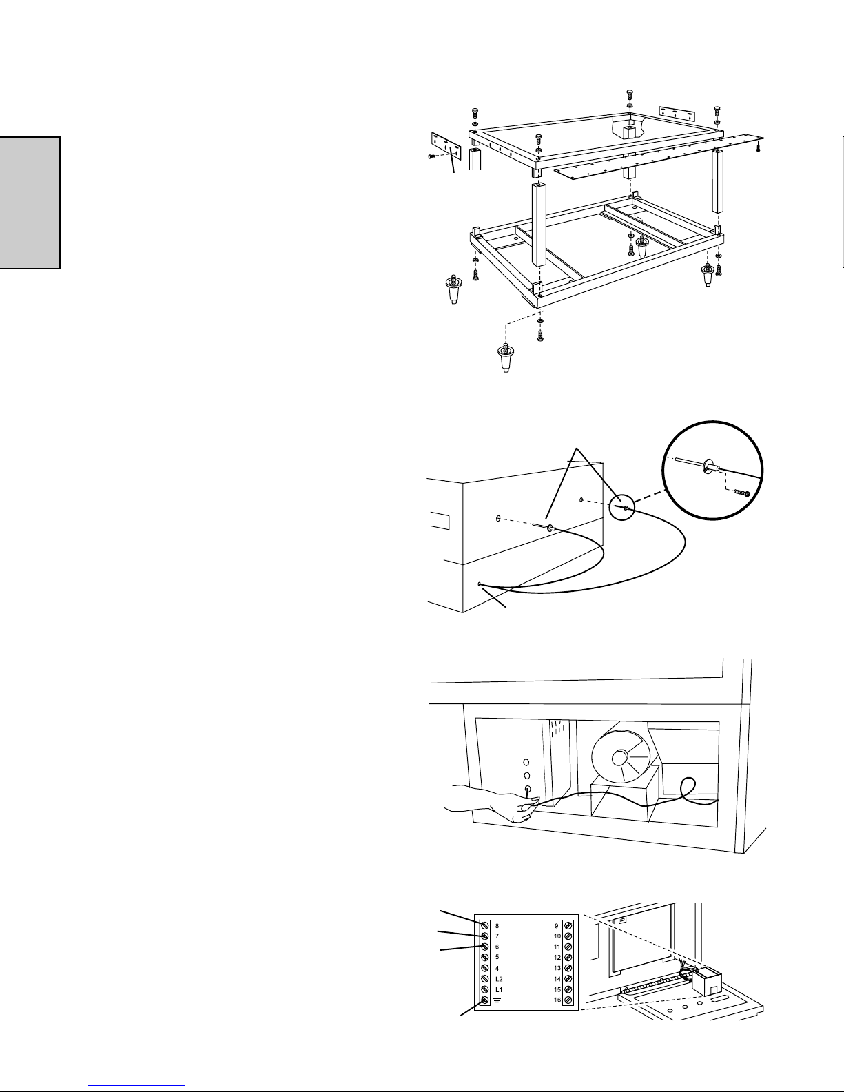
A. Caster Remova ............................................... 8
B. Stacking ............................................................ 8
C. Stands ............................................................... 8
D. F ue Vent(s) ...................................................... 8
IV. THERMOCOUPLE INSTALLATION ......................... 8
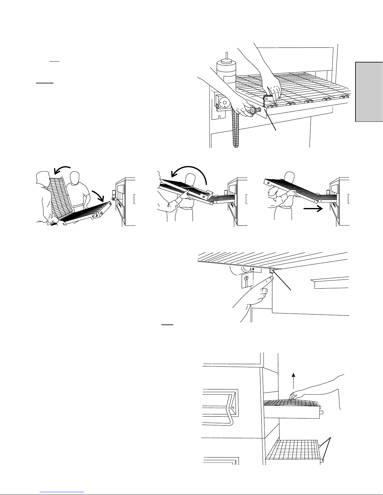
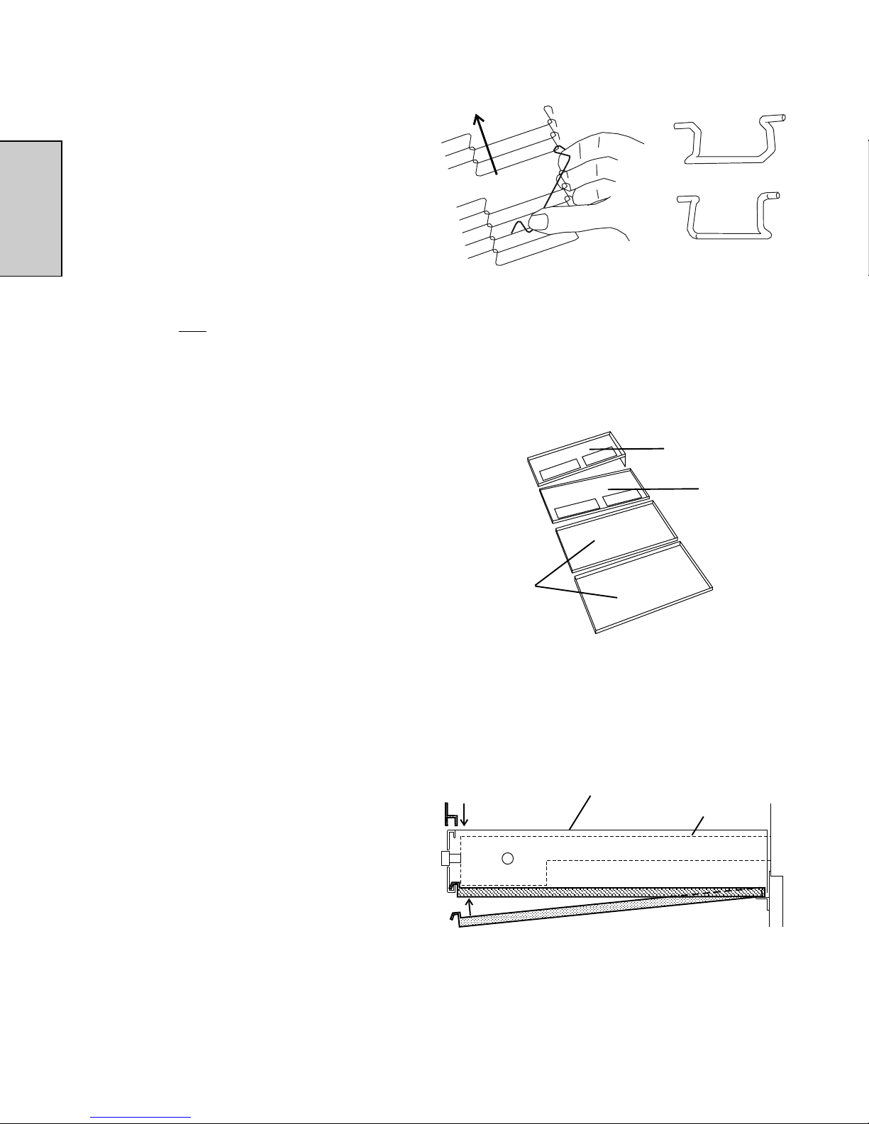
V. CONVEYOR INSTALLATION ................................... 9
VI. FINAL ASSEMBLY ................................................... 10
TABLE OF CONTENTS
VII. ELECTRICAL SUPPLY ........................................... 11
A. Additiona Information - Gas Ovens ................ 11
B. Additiona Information - E ectric Ovens .......... 11
C. Connection ...................................................... 11
VIII. GAS SUPPLY .......................................................... 11
A. Gas Uti ity Rough-in Recommendations ....... 12
B. Connection ...................................................... 12
C. Preparation for Use with Various Gases ....... 13
D. Rep acing the Gas Orifices ............................. 13
E. Checking the Gas Supp y (In et) Pressure .... 14
F. Adjusting the Orifice (Manifo d) Pressure
and Heat Input ................................................. 14
SECTION 3 - OPERATION ..................................................... 15
I. LOCATION AND DESCRIPTION OF CONTROLS . 15
A. "BLOWER" ( ) Switch ................................... 15
B. "HEAT" ( ) Switch ......................................... 15
C. "CONVEYOR" ( ) Switch ............................. 15
D. "RESET" ( ) Switch ....................................... 15
E. Conveyor Speed Contro er ............................. 15
F. Digita Temperature Contro er ....................... 15
G. Machinery Cpt. Access Pane Safety Switch .. 15
II. NORMAL OPERATION, STEP-BY-STEP ................ 16
A. Dai y Startup Procedures ................................ 16
B. Dai y Shutdown Procedures ........................... 16
III. QUICK REFERENCE: DIGITAL TEMP CONTROL . 17
IV. QUICK REFERENCE: TROUBLESHOOTING ....... 18
SECTION 4 - MAINTENANCE ................................................. 19
I. MAINTENANCE - DAILY .......................................... 19
II. MAINTENANCE - MONTHLY .................................. 20
III. MAINTENANCE - EVERY 3 MONTHS .................... 21
IV. MAINTENANCE - EVERY 6 MONTHS .................... 22
V. KEY SPARE PARTS KIT ......................................... 22
SECTION 5 - ELECTRICAL WIRING DIAGRAMS ................... 23
I. WIRING DIAGRAM, PS360-U/-L ELECTRIC OVEN,
380-400V, 50Hz, 1Ph .............................................. 23
II. WIRING DIAGRAM, PS360-U/-L OR PS360WB-U/-L
GAS OVEN, 220-230V, 50Hz, 1 Ph......................... 24
page page
4
ENGLISH
SECTION 1 - DESCRIPTION
II. OVEN COMPONENTS - see Figure 1-1.
A. Crumb Pans Catch crumbs and other materia that drop
through the conveyor be t. One crumb pan is ocated
underneath each end of the conveyor.
B. Conveyor Drive Motor Moves the conveyor.
C. Conveyor Moves the food product through the oven.
D. End Plugs A ow access to the oven's interior.
E. Serial Plate Provides specifications for the oven that affect
insta ation and operation.
F. Window A ows the user to see and access food products
inside the baking chamber.
G. Machinery Compartment Access Panel A ows access
to the oven's interior components. No user-servicab e
parts are ocated in the machinery compartment.
H. Control Compartment Access Panel A ows access to
the contro components. No user-servicab e parts are
ocated in the contro compartment.
I. Control Panel Location of the operating contro s for the
oven.
I. OVEN USES
PS300 Series Ovens can be used to bake and/or cook a
wide variety of food products, such as pizza, pizza-type
products, cookies, sandwiches and others.
Not Shown:
J. Eyebrows (on ovens so equipped) Can be adjusted to
various heights to prevent heat oss into the environment.
K. Conveyor End Stop Prevents food products from fa ing off
the end of the moving conveyor.
L. Gas Burner (gas ovens) or Heating Elements (electric
ovens) Heats air, which is then projected to the air fingers
by the b owers.
M. Blowers Fans that project hot air from the burner to the air
fingers.
N. Air Fingers Project streams of hot air onto the food product.
Figure 1-1 - Oven Components
III. OVEN SPECIFICATIONS
Table 1-1 Dimensions PS360U, PS360L PS360WB-U, PS360WB-L
Overall Height
Lower oven, with top and legs 1143mm 1143mm
Upper oven, with stand and top 1638mm 1638mm
Double oven (two-sta k) 2089mm 2089mm
Overall Depth (including rear shr uds and fr nt wind w) 1194mm 1397mm
Overall Length 2299mm 2299mm
C nvey r Width, Single Belt Ovens 813mm 1016mm
C nvey r Width, Split Belt Ovens 2 x 381mm 2 x 483mm
Rec mmended Minimum Clearances
Rear of oven (in . rear shrouds) to wall 25mm 25mm
Conveyor extension to wall (both ends) 0mm 0mm
Table 1-2 General specifications (per oven cavity)
PS360U, PS360L Gas PS360-U, PS360-L Electric PS360WB-U, PS360WB-L Gas
Weight 583kg 583kg 674kg
Shipping Weight 617kg 617kg 708kg
Shipping Cart n V l. 3.00m33.00m33.65m3
Rated Heat Input 34,020k al, 40kW 26kW 42,840k al, 50kW
Max. Operating Temp. < - - - - - - - - - - - - - - - - - - 288°C - - - - - - - - - - - - - - - - - - >
Air Bl wers < - - - - - - - 2 blowers at 43.9m3/min. at 1700 RPM, - - - - - - - >
2.2 m water stati pressure
Air Jet Vel city (avg.) < - - - - - - - - - - - - - - - 1320 m/se . - - - - - - - - - - - - - - - >
Warmup Time < - - - - - - - - - - - - - - - - 15 minutes - - - - - - - - - - - - - - - - >
A
B
CD F E
H,I
G
5
ENGLISH
SECTION 2 - INSTALLATION
WARNING
Do not obstruct the f ow of combustion and venti ation air to and from your oven. There must be no
obstructions around or underneath the oven. Constructiona changes to the area where the oven is
insta ed sha not affect the air supp y to the oven.
NOTE
There must be adequate c earance between the oven and combustib e construction. C earance
must a so be provided for servicing and for proper operation.
NOTE
An e ectrica wiring diagram for the oven is ocated inside the machinery compartment.
NOTE
All aspects of the oven installation, including placement, utilit connections, and ventilation requirements,
must conform with an applicable local, national, or international codes. These codes supercede the require-
ments and guidelines provided in this manual.
WARNING
The oven must be insta ed on an even ( eve ) non-f ammab e f ooring and any adjacent wa s must be non-
f ammab e. Recommended minimum c earances are specified in the Description section of this Manua .
WARNING - After any conversions, readjustments, or service work on the oven:
 Perform a gas eak test.
 Test for correct air supp y, particu ar y to the burner b ower.
 Test for proper combustion and gas supp y.
 Check that the venti ation system is in operation.
Table 1-3 Electrical specifications (per oven cavity)
Main Bl wer C ntr l Current
Oven M del V ltage Circuit V ltage Phase Freq. Draw * P les Wires
Gas Ovens 220-230V 120V (transformer) 1 Ph 50 Hz 8A 2 Pole 3 Wire (1 hot, 1 neut, 1 gnd)
Ele tri Ovens 380-400V 120V (transformer) 1 Ph 50 Hz 39A 2 Pole 5 Wire (3 hot, 1 neut, 1 gnd)
* CAUTION: The urrent draw shown in the hart above is an average value for normal operation. The initial amperage draw on oven startup
may ex eed the listed value.
IMPORTANT: Additional ele tri al information is provided on the oven's serial plate, and on the wiring diagram inside the ma hinery ompartment.
Table 1-4 Gas orifice and pressure specifications (per oven cavity)
Supply (inlet) Pressure (mbar)
IE,IT, AT,CH, Orifi e
Main Pilot Bypass PT,ES, DK,FI, (manifold) Rated
Orifi e Orifi e Orifi e GB DE NL BE,FR SE pressure Heat Supply Gas
Gas Type dia. dia. dia. II2H3+ II2ELL3B/P II2L3B/P II2E+3+ II2H3B/P (mbar) Input Volume Flow
PS360U, PS360L
Natural, G20 5.50mm 0.635mm 1.65mm 20 20 20 25 20 6.8 40kw 4.2m3h 70.0
l
/min
Natural, G25 5.50mm 0.635mm 1.65mm 20 25 10.5 40kw 4.2m3h 81.7
l
/min
Natural, G20, G25 4.50mm 0.635mm 1.50mm 20 20 25 20 25 20 6.8 10.5 40kw 4.2 4.9m3h 70.0 81.7
l
/min
Liquid, G30 2.70mm 0.381mm 0.85mm 29 37 28 30 29 37 50 * 40kw 3.1kg/h
Liquid, G30, G31 3.10mm 0.381mm 0.95mm 50 30 50 * 40kw 3.1kg/h
PS360WB-U, PS360WB-L
Natural, G20 6.30mm 0.635mm 2.30mm 20 20 20 25 20 6.8 50kw 5.3m3h 88.0
l
/min
Natural, G25 6.30mm 0.635mm 2.30mm 20 25 10.5 50kw 6.1m3h 102.4
l
/min
Natural, G20, G25 5.40mm 0.635mm 2.00mm 20 20 25 20 25 20 6.8 10.5 50kw 5.3 6.1m3h 88.0 102.4
l
/min
Liquid, G30 3.10mm 0.381mm 1.40mm 29 37 28 30 29 37 50 * 50kw 3.9kg/h
Liquid, G30, G31 3.50mm 0.381mm 1.40mm 50 30 50 * 50kw 3.9kg/h
* Pressure regulator (governor) not in operation, system at supply (inlet) pressure.
Orifi e pressures apply to 15°C, 1.013mbar dry gas.
WARNING
Keep the app iance area free and c ear of combustib es.
6
ENGLISH
SECTION 2 - INSTALLATION
Fig. 2-1 - Installation Kit
I. INSTALLATION KIT
A. Installation kit components (one kit required per cavity)
Item Descripti n Part Number L wer Oven w/ T p L wer Oven w/T p Upper Oven
1 Legs, adjustable 22450-0028 4 4 --
2a Conveyor End Stop - PS360/360S
 Single Belt 35000-1103 1 1 1
 Split Belt 35509 2 2 2
2b Conveyor End Stop - PS360WB (Single or Split Belt) 36526 1 1 1
3 Atta hment Plate, upper oven 35122-0049 -- -- 2
4 Thermo ouple 33812-1 2 2 2
5 S rew, #10-32 x 3/8" 21256-0008 2 2 2
6 Cable Clamp 27276-0001 1 1 1
7 S rew, #2PT 10-16 x 3/4" HWH 21292-0001 2 2 14
8 Owner's Operating and Installation Manual 46486 1 1 1
9 Authorized Servi e Agen y Listing 1002040 1 1 1
B. Additional installation kit components for gas ovens
Item Descripti n Part Number L wer Oven w/ T p L wer Oven w/T p Upper Oven
5 S rew, #10-32 x 3/8" 21256-0008 1 1 1
7 S rew, #2PT 10-16 x 3/4" HWH 21292-0001 2 2 2
10 Gas hose, flexible 22361-0001 1 1 1
11a Flue vent, 14" (356mm) 30773 -- 1 --
11b Flue vent, 29-1/2" (749mm) 30759 -- -- 1
11 Flue vent, 50" (1270mm) 30758 1 -- --
1
2
45
6
89
10
11
7
3
7
ENGLISH
458mm 305mm
76mm
51mm
minimum
B. Recommendations
NOTE THAT THE HOOD DIMENSIONS SHOWN IN FIGURE 2
ARE RECOMMENDATIONS ONLY. LOCAL, NATIONAL, AND
INTERNATIONAL CODES MUST BE FOLLOWED WHEN
INSTALLING THE VENTILATION SYSTEM. ANY APPLICABLE
LOCAL AND NATIONAL CODES SUPERSEDE THE
RECOMMENDATIONS SHOWN IN THIS MANUAL.
The rate of air f ow exhausted through the venti ation system
may vary depending on the oven configuration and hood design.
Consu t the hood manufacturer or venti ation engineer for these
specifications.
To avoid a negative pressure condition in the kitchen area,
return air must be brought back to rep enish the air that was
exhausted. A negative pressure in the kitchen can cause heat-
re ated prob ems to the oven components as if there were no
venti ation at a . The best method of supp ying return air is
through the heating, venti ation and air conditioning (HVAC)
system. Through the HVAC system, the air can be temperature-
contro ed for summer and winter. Return air can a so be
brought in direct y from outside the bui ding, but detrimenta
effects can resu t from extreme seasona hot and co d
temperatures from the outdoors.
NOTE: Return air from the mechanically driven system must not
blow at the opening of the baking chamber. Poor oven baking
performance will result.
C. Other ventilation concerns
 Specia ocations, conditions, or prob ems may require the
services of a venti ation engineer or specia ist.
 Inadequate venti ation can inhibit oven performance.
 It is recommended that the venti ation system and duct
work be checked at prevai ing interva s as specified by the
hood manufacturer and/or HVAC engineer or specia ist.
A. Requirements
CAUTION
CAUTION
Gas oven installations REQUIRE a mechanically driven
ventilation system with electrical e haust air sensing control.
A mechanically driven ventilation system is STRONGLY
RECOMMENDED for electric oven installations.
PROPER VENTILATION OF THE OVEN IS THE
RESPONSIBILITY OF THE OWNER.
II. VENTILATION SYSTEM
IMPORTANT
W ere national or local codes require t e
installation of fire suppression equip-
ment or ot er supplementary equipment,
DO NOT mount t e equipment directly to
t e oven.
MOUNTING SUCH EQUIPMENT ON
THE OVEN MAY:
 VOID AGENCY CERTIFICATIONS
 RESTRICT SERVICE ACCESS
 LEAD TO INCREASED SERVICE
EXPENSES FOR THE OWNER
Fig. 2-2 - Ventilation System
458mm
SECTION 2 - INSTALLATION
8
ENGLISH
SECTION 2 - INSTALLATION
IV. THERMOCOUPLE INSTALLATION
1. Insta one thermocoup e sensing bu b into each of the two
ho es in the rear pane of the oven, as shown in Figure 2-4.
Fasten each thermocoup e in p ace using one of the #10-
32 x 3/8" screws supp ied in the Insta ation Kit.
2. Thread BOTH sets of thermocoup e eads through the
grommet and into the machinery compartment, as shown
in Figure 2-4.
3. Remove the right-side access pane of the machinery
compartment.
4. Thread the thermocoup e eads through the side of the
machinery compartment as shown in Figure 2-5, and into
the e ectrica box (at the right-front of the machinery compart-
ment).
5. Connect BOTH sets of thermocoup e eads to the tempera-
ture contro er as shown in Figure 2-6. Note that the two
thermocoup es are now tied together at the temperature
contro er.
6. Rep ace the right-side pane of the machinery compart-
ment.
7. Repeat Steps 1-6 for any other oven cavities in the insta a-
tion.
8=White=Positive
7=Red=Negative
R=No Connection
Ground= hielded cable
Figure 2-4 - Thermocouple Installation Locations
Figure 2-5 - Placing the Thermocouple Leads
Figure 2-6 - Thermocouple Lead Connections
III. ASSEMBLY
A. Caster Removal
After moving the ovens in to the insta ation ocation, remove the
casters attached to each oven cavity. These casters are provided
for pre-insta ation movement ONLY.
B. Stacking
If the insta ation wi inc ude upper ovens mounted atop ower
ovens, stack the oven cavities.
C. Stands
If the insta ation inc udes ovens that are to be mounted on
stands, assemb e the ovens to the stands at this time. An
exp oded view of the stand is shown in Figure 2-3.
D. Flue Vent(s)
For gas ovens, attach one f ue vent to the rear wa of each oven
cavity. Use one #10-16 x 3/8" and two #10-32 x 3/4" screws for
each f ue vent. These screws are provided in the Insta ation Kit.
Figure 2-3 - Exploded View, Oven Stand
Attachment
plates inc. w/
upper oven
installation kit
Thermocouples
Grommet-protected hole
9
ENGLISH
SECTION 2 - INSTALLATION
V. CONVEYOR INSTALLATION
NOTE
Split belt conveyors can only be installed from the end of the
oven with the drive motor.
Single-belt conveyor assemblies may be inserted into either
end of the oven. If it is to be installed from the end of the oven
without the drive motor, the drive sprocket assembly must be
removed.
To remove the drive sprocket (if necessary), loosen the set
screw on the conveyor collar as shown in Figure 2-7. Then, pull
the sprocket assembly straight out.
1. Lift the conveyor and position it in the oven as shown in
Figure 2-8.
Figure 2-8 - Inserting the Conveyor
2. Continue moving the conveyor into the oven unti the frame
protrudes equa y from each end of the oven (about 457mm).
3. Check that the retainers ocated on the underside of the
conveyor frame rest firm y against the ower end p ug, as
shown in Figure 2-9.
NOTE
Each oven has retainer clips on the bottom of the conveyor
frame, as shown in Figure 2-9. The clips are only located
on the left (drive) side of the frame.
4. When the conveyor is positioned proper y, check for free-
dom of movement of the conveyor be t by pu ing it for about
60 to 90 cm with your fingers. The conveyor must move
free y.
5. If the drive sprocket was removed when insta ing the
conveyor, rep ace it at this time.
6. Insta the drive chain between the conveyor drive sprocket
and the motor sprocket. To insta the chain, it wi be
necessary to ift the drive end of the conveyor s ight y. The
drive motor and sprocket are shown in Figure 2-7.
7. Insta the conveyor drive motor cover and tighten its hanger
screw (on the rear wa of the oven).
8. Check the tension of the conveyor be t as shown in Figure
2-10. The be t shou d ift between 75-100mm. DO NOT
OVERTIGHTEN THE CONVEYOR BELT.
NOTE
If necessary, the belt tension can be adjusted by turning the
conveyor adjustment screws, located at the idler (right) end
of the conveyor. See Figure 2-10.
Figure 2-9 - Conveyor retainers
Figure 2-10 - Checking the conveyor tension
75-100mm
vertical
deflection
Retainer clip
Figure 2-7 - Removing the Conveyor Drive Sprocket
Loosen conveyor collar
set screw, then pull shaft
straight out
Conveyor
tension
adjustment
screws (idler
end only)
10
ENGLISH
VI. FINAL ASSEMBLY
1. Assemb e the end p ugs and motor housing onto the oven.
2. S ide the conveyor extensions over the ends of the conveyor
frame. Be sure that the extension with the drive sprocket
opening is p aced on the drive end.
3. Refer to Figure 2-12 for the correct ocation of each crumb
tray. Then, insta the crumb trays underneath the conveyor
as shown in Figure 2-13. First, p ace the inside edge of the
tray onto the bracket attached to the end p ug. Then, swing
the outside edge of the tray up and into p ace.
4. Press the end stop down over the edge of the conveyor
extension at the exit end of the oven. See Figure 2-13.
5. Adjust the bottom section of the egs so that the oven is
eve .
Figure 2-13 - Crumb trays, extensions, and end stop
Crumb tray
End
stop Conveyor extension
Conveyor frame
Figure 2-12 - Crumb tray positions
Upper Oven
(Drive End)
Upper Oven
(Idler End)
Lower Oven
Figure 2-11 - Conveyor and Master Link Orientation
Direction
of travel
Outside master link
orientation
CORRECT
master link
position
Incorrect
master link
position
Inside master link
orientation
9. If necessary, inks can be added to or removed from the
conveyor be t to achieve the correct def ection of 75-100mm.
If inks must be removed from the be t, it can be reattached
to the conveyor as fo ows:
a. The conveyor be t inks must be oriented as shown in
Figure 2-11.
b. The smooth side of the conveyor be t must face UP.
c. Connect the inside master inks. Check that the inks
are oriented as shown in Figure 2-11.
d. Connect the outside master inks. Note that the
outside master inks have right and eft sides. The
right-side master ink has an open hook facing you, as
shown in Figure 2-11.
e. Check for freedom of movement of the conveyor be t by
pu ing it for about 60 to 90 cm with your fingers. The
conveyor must move free y.
f. Return to Step 8, above, to re-check the be t tension.
SECTION 2 - INSTALLATION
11
ENGLISH
VIII. GAS SUPPLY
CAUTION
DURING PRESSURE TESTING NOTE ONE OF THE FOLLOW-
ING
1. The oven and its individual shutoff valve must be
disconnected from the gas supply piping system during
any pressure testing of that system at test pressure in
excess of 3.45 kPa.
2. The oven must be isolated from the gas supply piping
system by closing its individual manual shutoff valve
during any pressure testing of the gas supply piping
system at test pressure equal to or less than 3.45 kPa.
3. If incoming pressure is over 50mbar, a separate regu-
lator MUST be installed in the line BEFORE the individual
shutoff valve for the oven.
WARNING: To prevent damage to the control valve regu-
lator during initial turn- on of gas, it is very important to
open the manual shutoff valve very slowly.
After the initial gas turn-on, the manual shutoff valve must
remain open except during pressure testing as outlined
in the above steps or when necessary during service
maintenance.
Figure 2-14 - Utility Connection Locations
Electrical
Junction Box
Gas ovens:
19mm pipe for
gas utility connection
Electric ovens:
Cutout for electrical
connection
VII. ELECTRICAL SUPPLY
WARNING
Authorized supplier personnel normally accomplish
the connections for the ventilation system, electric supply,
and gas supply, as arranged by the customer. Following
these connections, the factory-authorized installer can
perform the initial startup of the oven.
NOTE: All aspects of the electrical supply connection must
comply with current IEC/CEE requirements and with all
applicable local, national, and international codes.
Check the oven seria p ate before making any e ectric supp y
connections. E ectric supp y connections must agree with data
on the oven seria p ate. The ocation of the seria p ate is shown
in Figure 1-1 (in Section 1, Description).
A fused disconnect switch or a main circuit breaker (customer
furnished) MUST be insta ed in the e ectric supp y ine for each
oven cavity. The circuit breaker/disconnect must have 3mm
contact gaps breaking a po es of the supp y. It is recommended
that this circuit breaker/disconnect have ockout/tagout capabi ity.
The supp y conductors are to be 90°C-rated copper wiring.
Additiona wiring information is shown on the wiring diagrams
in Section 5, E ectrica Wiring Diagrams and inside the machin-
ery compartment of the oven.
The oven requires a ground connection to the oven ground
screw ocated in the e ectrica junction box. (The box is shown
in Figure 2-14.) The ground connection must comp y with
current IEC/CEE requirements and with a app icab e oca ,
nationa , and internationa codes. If necessary, have the
e ectrician supp y the ground wire. Do NOT use the wiring
conduit or other piping for ground connections!
A. Additional Information - Gas Ovens
A e ectric supp y connections are made via the e ectrica
junction box on the rear of the oven, shown in Figure 2-14. The
power ines then connect to the oven circuits through safety
switches ocated inside the machinery compartment and each
b ower motor compartment. These switches interrupt e ectric
power to the oven when the Machinery Compartment Access
Pane is opened, OR when either of the b ower or rear shrouds
is removed.
B. Additional Information - Electric Ovens
A cutout in the back wa of the machinery compartment provides
access to the e ectrica supp y connections. See Figure 2-14.
The actua wiring connections are made at the e ectrica junction
box.
C. Connection
Refer to the wiring diagram inside the machinery compartment,
or in Section 5 of this Manua , to determine the correct
connections for the e ectrica supp y ines. Connect the supp y
as indicated on the wiring diagram.
If required by nationa or oca codes, connect an equipotentia
ground wire to the ug next to the symbo . The equipotentia
ground connection must meet a app icab e nationa and o-
ca code requirements.
SECTION 2 - INSTALLATION
12
ENGLISH
Figure 2-16 - Gas Burner and Piping Assembly
Multifunction
Gas Valve
A. Gas Utility Rough-In Recommendations
The fo owing gas system specifications are STRONGLY
RECOMMENDED. Deviating from these recommendations
may affect the baking performance of the oven.
Gas Meter
 One or two oven cavities: 354
l/sec
meter
 Three or four oven cavities: 566
l/sec
meter
Gas Line
 DEDICATED LINE from the gas meter to the oven
 50.8mm pipe for natura gas
 38.1mm pipe for propane
 Maximum ength: 61m. Each 90° e bow equa s 2.13m of
pipe.
B. Connection
WARNING
Some procedures in this section may require conver-
sions, readjustments, or service on the oven's gas system.
Before performing these procedures, check that the main
gas supply valve and the circuit breaker/fused disconnect
are in the OFF ("O") position. After completing these proce-
dures, perform a gas leak test before operating the oven.
CAUTION
The terms of the oven's warranty require all start-ups, conver-
sions and service work to be performed by a Middleby Marshall
Authorized Service Agent. The installation, start-up and changes
required when changing from one gas type to another can be
performed ONLY by a certified professional.
NOTE: The gas supply connection should be according to
applicable ISO 228-1 or ISO 7-1 recommendations. All aspects
of the gas supply connection must comply with current IEC/CEE
requirements and with all applicable local, national, and inter-
national codes.
Check the ovens gas supp y requirements before making the
gas uti ity connection. Gas supp y requirements are isted on
the ovens seria p ate.
Check the seria p ate to determine the type of gas to be used
with the oven. Check that the gas type indicated matches the
oca supp y at the insta ation. If the gas type on the seria p ate
does NOT match the oca supp y, directions for converting the
oven for use with other gases are described in Preparation for
Use with Various Gases, in this section.
Refer to the instructions in the gas hose package (inc uded in
the Insta ation Kit) before connecting the gas ine. One gas ine
connection method is shown in Figure 2-15; however,
comp iance with the app icab e standards and regu ations is
mandatory.
Orifice
(manifold)
pressure tap
Governor
disabled for
liquid
propane (LP)
operation
Governor
enabled for
natural gas
operation
Pilot pressure tap
Low Flame
Bypass Line
High Flame
olenoid Valve
Gas Burner
Burner Blower
upply (inlet)
pressure tap
Union
Pilot Line
Multifunction Gas Valve
Figure 2-15 - Flexible Gas Hose Installation
Appliance
Connection/Male
Nipple
Flexible
Gas Hose
Full-Flow Gas
hutoff Valve
To Gas
upply Pipe
90°
Elbow
SECTION 2 - INSTALLATION
13
ENGLISH
C. Preparation for Use with Various Gases
Before proceeding to set up the oven for a specific gas, check
that the main gas supp y va ve and the circuit breaker/fused
disconnect are in the OFF ("O") position.
The main and pi ot orifices must match the sizes shown in the
Gas Orifices and Pressure Specifications tab e, near the
beginning of this Section. If necessary, rep ace the orifices.
Refer to Part D, Rep acing the Gas Orifices.
The orifice (manifo d) pressure shou d be adjusted to the va ue
shown in the Gas Orifices and Pressure Specifications tab e for
the specific gas type and ocation.
1. For Use with Natural Gas
The actua heat input to the oven must match the rated heat
input. The input to the burner can be determined using the
orifice (manifo d) pressure data or by the vo ume supp ied
using the gas meter. Both of these procedures are
described in Part F, Adjusting the Orifice (Manifo d) Pressure
and Heat Input.
If the measured input does not correspond with the rated
input (shown in the Gas Orifices and Pressure Specifications
tab e), check first that the correct orifices are insta ed. If the
orifices are correct, check and correct the supp y and orifice
pressures to obtain the correct input based on the gas
meter reading.
2. For Use with Liquid Propane (LP) Gas
When using iquid gas, the converter in the mu tifunction
gas va ve must be removed, and then rep aced INVERTED
from its former position. See Figure 2-16. Inverting the
converter wi disab e the governor. This step is on y
required if the supp y pressure is be ow 50mbar.
D. Replacing the Gas Orifices (if so required)
1. Replacing the Main Orifice
a. Check that the main gas supp y va ve and the circuit
breaker/fused disconnect are in the OFF ("O") position.
b. Open the union in the gas supp y ine. The union is
shown in Figure 2-16, on the previous page.
c. Refer to Figure 2-17. Unscrew the four hex screws that
ho d the venturi mounting p ate to the front of the
burner. Remove the gas train/venturi assemb y from
the oven.
d. Remove the two 1/2" nuts that secure the gas train to
the venturi mounting p ate.
e. Remove the main orifice using an 11/16" wrench.
f. Insta the new orifice.
2. Replacing the Pilot Orifice
NOTE: All natural gases use the same size pilot orifice
(0,635mm), as do all liquid propane (LP) gases (0,381mm).
Because of this, it is not normally necessary to replace the
pilot orifice unless converting the oven from natural to
propane, or from propane to natural, operation.
a. Refer to Figure 2-17. Unscrew the pi ot tube
compression nut and s ide it out of the way. Pu the
tube from the fitting to expose the pi ot orifice.
b. Remove the pi ot orifice.
c. S ip the new pi ot orifice into the pi ot tube.
d. Push the pi ot tube back into p ace unti it bottoms, and
ho d it in p ace. S ide the compression nut back into
p ace and engage the threads. Tighten the nut to a
snug fit with your fingers.
e. Gent y tighten the nut one comp ete turn with a wrench.
DO NOT OVERTIGHTEN THE COMPRESSION NUT.
3. Replacing the Bypass (Low Flame) Orifice
a. Refer to Figure 2-16. Note the ocations of the 1/2" hex
compression nuts that ho d the bypass ine in p ace.
Loosen the compression nuts using a 1/2" wrench.
b. Remove the bypass tube. Then, remove the bypass
orifice from the tube.
c. S ip the new orifice into the bypass tube.
d. Rep ace the tube onto its fittings on the so enoid va ve.
Whi e ho ding the tube in p ace, s ide the compression
nuts back into p ace and engage the threads. Tighten
the nut to a snug fit with your fingers.
e. Gent y tighten the nuts one comp ete turn with a wrench.
DO NOT OVERTIGHTEN THE COMPRESSION NUTS.
f. Rep ace the gas train and venturi by fo owing Steps a-
d in Rep acing the Main Orifice, above, in reverse order.
WARNING
After completing these procedures, perform a gas
leak test before operating the oven.
Figure 2-17 - Replacing the Main and Pilot Orifices
Main
orifice
Pilot
orifice
Pilot tube
Compression
nut
Main orifice
holder (attached
to gas train)
Venturi
assembly
Venturi
mounting
plate
Ignition
sensor
wire
SECTION 2 - INSTALLATION
14
ENGLISH
E. Checking the Gas Supply (Inlet) Pressure
1. Remove the supp y (in et) pressure cap screw from the
mu tifunction gas va ve. Attach a manometer to the stud.
2. Depress the machinery compartment safety switch to
a ow the oven to operate.
3. Open the main gas supp y va ve. Switch the circuit breaker/
fused disconnect to the ON ("I") position.
4. Start the oven and adjust the temperature contro er to the
maximum setting (288°C).
5. Measure the supp y (in et) pressure.
6. Switch the oven off. C ose the main gas supp y va ve, and
switch the circuit breaker/fused disconnect to the OFF ("O")
position. Remove the manometer, and rep ace the cap
screw onto the mu tifunction gas va ve.
7. Compare the measured supp y (in et) pressure to the
nomina pressures shown in the Gas Orifices and Pressure
Specifications tab e.
If the supp y pressure is ower or higher than the nomina
pressure, the reason shou d be investigated and the gas
supp ier contacted.
For natura gas ovens, if the measured supp y pressure is ower
than 17mbar, or higher than 25mbar, contact the gas supp ier.
DO NOT OPERATE THE OVEN or adjust the oven contro s.
F. Adjusting the Orifice (Manifold) Pressure and Heat Input
To use the orifice pressure method, you must know the specific
gas type and qua ity used. If using the orifice pressure method,
you shou d doub e-check the input using the vo umetric method.
To use the vo umetric method, you must know the heat va ue
(HuB) of the gas used. This information is avai ab e from your
gas supp ier.
During these measurements, do not operate any other
app iances that use the same gas meter as the oven.
1. Orifice (Manifold) Pressure Method
a. Check that the main gas supp y va ve and the circuit
breaker/fused disconnect are in the OFF ("O") position.
b. Remove the regu ated (manifo d) pressure cap screw
from the mu tifunction gas va ve. Attach a manometer
to the stud.
c. Remove the cap screw from the pressure adjustment
screw (governor) on the mu tifunction gas va ve.
d. Depress the machinery compartment safety switch to
a ow the oven to operate.
e. Open the main gas supp y va ve. Switch the circuit
breaker/fused disconnect to the ON ("I") position.
f. Start the oven and adjust the temperature contro er to
the maximum setting (288°C).
g. Adjust the pressure adjustment screw as necessary
to match the correct pressure for the oven's specific
gas type. Refer to the Gas Orifices and Pressure
Specifications tab e. Turning the adjustment screw
c ockwise increases the f ow, whi e turning it
counterc ockwise reduces the f ow.
h. Switch the oven off. C ose the main gas supp y va ve,
and switch the circuit breaker/fused disconnect to the
OFF ("O") position. Remove the manometer, and
rep ace the cap screws onto the mu tifunction gas
va ve.
Consumption (m3/hr.) = NB (Rated input in kW)
HuB (Heat [Ca orific] va ue
of gas in kW/m3)
=
Time (in minutes) of
0.1m3 of gas usage
2. Volumetric Method
a. Determine the time of 0.1m3 (100 iters) of gas usage
as fo ows.
b. Check that the main gas supp y va ve and the circuit
breaker/fused disconnect are in the OFF ("O") position.
c. Remove the cap screw from the pressure adjustment
screw (governor) on the mu tifunction gas va ve.
d. Depress the machinery compartment safety switch to
a ow the oven to operate.
e. Open the main gas supp y va ve. Switch the circuit
breaker/fused disconnect to the ON ("I") position.
f. Start the oven and adjust the temperature contro er to
the maximum setting (288°C).
g. Adjust the pressure adjustment screw as necessary
to match the ca cu ated vo ume using the time (in
minutes) of 0.1m3 of gas usage. Turning the
adjustment screw c ockwise increases the f ow, whi e
turning it counterc ockwise reduces the f ow.
h. Record the reading obtained from the gas meter and
ca cu ate the obtained gas f ow. Compare this va ue
to the information in the Gas Orifices and Pressure
Specifications tab e.
i. Switch the oven off. C ose the main gas supp y va ve,
and switch the circuit breaker/fused disconnect to the
OFF ("O") position. Rep ace the cap screw onto the
mu tifunction gas va ve.
6
Consumption
SECTION 2 - INSTALLATION
15
ENGLISH
SECTION 3 - OPERATION
I. LOCATION AND DESCRIPTION OF CONTROLS
Fig. 3-1 - Control Panel
"BLOWER" Switch Turns the b owers and
coo ing fans on and off. The HEAT Switch has
no effect un ess the BLOWER Switch is in the
ON position.
A.
"HEAT" Switch A ows the burner or heating
e ements, as appropriate for the oven mode , to
activate. Activation is determined by the set-
tings on the Digita Temperature Contro er.
"CONVEYOR" Switch Turns the conveyor drive
motor on and off.
B.
C.
E.
F.
"RESET" Switch Gas ovens on y. I uminates
if the gas burner does not ight. The switch can
be pressed repeated y to attempt to ight the
burner. If the burner does not ight within 15
minutes, the "RESET" ( ) switch is ocked out.
Conveyor Speed Controller Adjusts and dis-
p ays the bake time. Sing e-be t ovens have one
contro er. Sp it be t ovens have one contro er
for each conveyor be t, abe ed "FRONT" and
"BACK."
Digital Temperature Controller Continuous y
monitors the oven temperature. Settings on the
Digita Temperture Contro er contro the acti-
vation of the burner or heating e ements.
D.
NOT SHOWN:
G. Machinery Compartment Access Panel Safety Switch
Disconnects e ectrica power to the contro s and the b ow-
ers when the machinery compartment access pane is
opened. The pane shou d on y be opened by authorized
service personne .
D.
"RE ET"
( ) switch
GAS OVENS ONLY
A.
"BLOWER"
(" ")
switch
F.
Digital Temperature
(" ") controller
E.
Conveyor peed
(" ") controller(s)
B.
"HEAT"
(" ")
switch
C.
"CONVEYOR"
(" ")
switch
16
ENGLISH
A. DAILY STARTUP PROCEDURE
3. Turn the "CONVEYOR"
() switch to the ON
("I") position.
4. If necessary, adjust the
conveyor speed setting
by pressing the or
pushbuttons on the con-
veyor speed contro er to
change the disp ayed
bake time.
Some ovens may be
equipped with a
thumbwhee speed con-
tro er. For these ovens,
turn the three
thumbwhee s to change
the disp ayed bake time.
II. NORMAL OPERATION - STEP-BY-STEP
SECTION 3 - OPERATION
2. Turn the "BLOWER" ( )
switch to the ON ("I")
position.
+wait
for
6. Turn the "HEAT" ( )
switch to the "ON" ("I")
position, and wait for the
"HEAT ON" ight to turn
on.
or
5. Adjust the temperature
contro er to a desired set
temperature, if neces-
sary.
 Press the Set Point
and Un ock keys at
the same time. Wait
for the "SET PT" ight
to turn on.
 Press the Up Arrow
and Down Arrow
Keys as necessary
to adjust the set-
point.
wait
for
1. Check that the circuit breaker/fused disconnect is in the on
position. Check that the window is c osed.
or
mins se s
thumbwheels
CAUTION
In case of power fai ure, turn a switches to the OFF ("O")
position, open the oven window, and remove the product.
After the power has been restored, perform the norma
startup procedure.
On gas ovens, the burner will not operate and gas will not
flow through the burner without electric power. No
attempt should be made to operate the oven during a
power failure.
7. (Gas ovens on y) If the "RE-
SET" ( ) switch i umi-
nates, the gas burner did
not ight. Press the "RE-
SET" ( ) switch (repeat-
ed y if necessary) to attempt to ight the burner.
NOTE: If the burner does not light within 15 minutes, the
oven enters a safety lockout mode that disables the "RE-
SET" () switch. If this occurs, turn the "HEAT" ( ),
"BLOWER" ( ), and "CONVEYOR" ( ) switches to the
"OFF" ("O") position. Wait for AT LEAST FIVE MINUTES.
Then, repeat the Daily Startup procedure.
8. (Optional) Press the Tem-
perature ( ) key to show
the Actua Temperature
in the disp ay, and wait
for the "ACTUAL TEMP"
ight to turn on. This a -
ows you to monitor the
oven temperature as it
rises to the setpoint.
1. Turn the "HEAT" ( ) and
"BLOWER" ( ) swit-
ches to the "OFF" ("O")
position. Note that the
b owers wi remain in op-
eration unti the oven has
coo ed to be ow 93°C.
7. Wait for the oven to heat to the setpoint temperature. Higher
setpoint temperatures wi require a onger wait. The oven
can reach a temperature of 232°C in approximate y 5
minutes.
3. Open the window to a ow the oven to coo faster.
2. Make certain that there
are no products eft on
the conveyor inside the
oven. Turn the "CON-
VEYOR" ( ) switch to
the "OFF" ("O") position.
B. DAILY SHUTDOWN PROCEDURE
9. A ow the oven to preheat for 10 minutes after it has reached
the set point temperature.
wait
for
+
4. After the oven has coo ed and the b owers have turned off,
switch the circuit breaker/fused disconnect to the off posi-
tion.
17
ENGLISH
SECTION 3 - OPERATION
III. UICK REFERENCE: DIGITAL TEMPERATURE CONTROLLER
Display
Shows the Set Point or
the Actua Tempera-
ture in degrees Fahr-
enheit (F) or Ce sius
(C).
"SP LOCK" Light
Lights when the set
point is ocked out
from changes. This
setting can on y be
changed by service
personne .
OVERTEMP Light
Lights when the oven
temperature is greater
than 343°C. Refer to
Quick Reference:
Troub eshooting in
this section.
Temperature Key
Press this key once to
view the Actua Tem-
perature in the Dis-
p ay.
Unlock Key
Press this key together
with the Set Point Key
to a ow the Set Point
to be changed.
Changes can on y be
made for 60 seconds.
Up Arrow and Down Arrow
Keys
Press these keys to adjust
the Set Point up or down. If
the Set Point wi not
change, refer to Set Point
Key and Un ock Key in this
section.
Set Point Key
Press this key together
with the Un ock Key to
a ow the Set Point to
be changed.
Changes can on y be
made for 60 seconds.
Service Key
For use by ser-
vice personne
on y.
"ACTUAL TEMP"
Light
Lights when the
Actua Tempera-
ture is shown in
the disp ay.
"SET PT" (setpoint)
Light
Lights when the set
point is shown in the
disp ay.
"HEAT ON" Light
Lights when the
burner or heating e e-
ments, as appropriate
for the oven mode ,
are in operation.
18
ENGLISH
IV. UICK REFERENCE: TROUBLESHOOTING
SYMPTOM PROBLEM SOLUTION
IF THESE STEPS FAIL TO RESOLVE THE PROBLEM, CONTACT YOUR LOCAL MIDDLEBY MARSHALL
AUTHORIZED SERVICE AGENT. A SERVICE AGENCY DIRECTORY IS SUPPLIED WITH YOUR OVEN.
SECTION 3 - OPERATION
 Check that the set temperature and bake time settings are
correct.
Food products are
overcooked or
undercooked.
Contro s may be set incor-
rect y.
 Turn the oven off, and a ow it to coo . Disconnect e ectrica
power to the oven.
 Check if the conveyor is b ocked by an object inside the oven.
 Refer to Section 4, Maintenance, for instructions on checking
the conveyor and drive chain tension.
Conveyor moves with a
jerky motion, or will not
move at all
Conveyor may be jammed
on an object in the oven, or
conveyor be t or drive chain
tension may be incorrect.
Oven is operating, but
little or no air is blowing
from air fingers
Air fingers may have been
reassemb ed incorrect y
after c eaning.
 Turn the oven off, and a ow it to coo . Disconnect e ectrica
power to the oven.
 Refer to Section 4, Maintenance, for instructions on reassem-
b ing the air fingers.
Oven will not heat Contro s may be set incor-
rect y.
 Check that the Set Point is correct y set.
 Check that both the "BLOWER"
( ) and "HEAT" ( ) Switches
are in the ON ("I") position.
 If the oven sti wi not heat,turn the "HEAT" ( ), "BLOWER"
( ), and "CONVEYOR" ( )switches to the "OFF" ("O")
position.
 Wait for AT LEAST FIVE MINUTES before restarting the oven.
 Repeat the Dai y Startup procedure. Check that the Set Point
is above 93°C.
appears in display,
oven is not heating
The oven did not reach
93°C within 15 minutes of
startup, and the oven has
stopped heating.
 Turn the "HEAT" ( ), "BLOWER" ( ), and "CONVEYOR"
()switches to the "OFF" ("O") position.
 Wait for AT LEAST FIVE MINUTES before restarting the oven.
 Repeat the Dai y Startup procedure.
"RESET" () switch is
illuminated, oven will not
heat
(gas ovens only)
The gas burner did not ight
within 90 seconds of turn-
ing the "HEAT" ( ) Switch
to the ON ("I") position.
 Press the "RESET" ( ) switch (repeated y if necessary) to
attempt to ight the burner.
 If the burner does not ight within 15 minutes, the oven wi enter
a safety ockout mode that disab es the "RESET" ( ) switch.
If this occurs, turn the "HEAT" ( ), "BLOWER" ( ), and
"CONVEYOR" ( )switches to the "OFF" ("O") position. Wait
for AT LEAST FIVE MINUTES before restarting the oven. Then,
repeat the Dai y Startup procedure.
Oven will not
turn on at all
E ectrica power may not be
reaching the oven, or the
contro s may be set incor-
rect y.
 Check that the circuit breaker/fused disconnect is turned on.
 Check that the "BLOWER" ( ) Switch is in the ON ("I")
position. The burner cannot engage unti the b owers are in
operation.
The oven temperature ex-
ceeded 343°C, and the
burner or heating e ements
were automatica y shut
down.
 Fo ow the procedures under Dai y Shutdown Procedures in
this section to shut down the oven. Contact your Midd eby
Marsha Authorized Service Agent to determine and correct the
cause of the condition to prevent damage to the oven.
light is lit, food product is
undercooked
19
ENGLISH
WARNING
Before ANY c eaning or servicing of the oven, perform the fo owing procedure:
1. Switch off the oven and a ow it to coo . Do NOT service the oven whi e it is warm.
2. Turn off the e ectric supp y circuit breaker(s) and disconnect the e ectric supp y to the oven.
3. If it is necessary to move a gas oven for c eaning or servicing, disconnect the gas supp y connection before moving the oven.
SECTION 4 - MAINTENANCE
WARNING
Possibi ity of injury from moving parts and e ectrica shock exists in this oven. Switch off and ockout/tagout the e ectric supp y
BEFORE beginning to disassemb e, c ean, or service any oven. Never disassemb e or c ean an oven with the BLOWER ( )
switch or any other circuit of the oven switched on.
CAUTION
NEVER use a water hose, water jet, or pressurized steam-c eaning equipment when c eaning this oven. DO NOT use
excessive amounts of water, to avoid saturating the oven insu ation. DO NOT use a caustic oven c eaner, which can damage
the a uminized bake chamber surfaces.
NOTE
ANY rep acement parts that require access to the interior of the oven may ONLY be rep aced by a Midd eby Marsha Authorized
Service Agent. It is a so strong y recommended that the 3-Month Maintenance and 6-Month Maintenance procedures in this
section be performed ONLY by a Midd eby Marsha Authorized Service Agent.
When a c eaning and servicing is comp ete:
1. If the oven was moved for servicing, return the oven to its
origina ocation. Adjust the egs so that they are seated
proper y on the f oor.
2. For gas ovens, reconnect the gas supp y.
3. Reconnect the e ectrica supp y.
4. For gas ovens, turn on the fu -f ow gas safety va ve. Test
the gas ine connections for eaks using approved eak
test substances or thick soap suds.
5. Turn on the e ectric supp y circuit breaker(s).
6. Perform the norma startup procedure.
I. MAINTENANCE - DAILY
A. Check that the oven is coo and the power is disconnected,
as described in the warning at the beginning of this Section.
B. C ean the outside of the oven with a soft c oth and mi d
detergent.
C. C ean ALL of the coo ing fan gri s and vent openings with a
stiff ny on brush.
D. Check that ALL coo ing fans are operating proper y.
CAUTION
If a cooling fan is not operating correctly, it must be replaced
IMMEDIATELY. Operating the oven without adequate
cooling can seriously damage the oven's internal compo-
nents.
E. C ean the conveyor be ts with a stiff ny on brush. This is
more easi y accomp ished by a owing the conveyor to run
whi e you stand at the exit end of the conveyor. Then, brush
the crumbs off the conveyor as it moves.
F. Remove and c ean the crumb trays. Be sure to rep ace the
trays in the same positions from which they were removed,
because they are NOT identica . Refer to Figure 4-1.
G. C ean the window in p ace.
Figure 4-1 - Crumb trays
Upper oven
(drive end)
Upper oven
(idler end)
Lower oven
20
ENGLISH
II. MAINTENANCE - MONTHLY
A. Check that the oven is coo and the power is disconnected,
as described in the warning at the beginning of this Section.
B. Remove the crumb trays, drive motor shroud, and conveyor
extension covers from the oven.
C. Lift the drive end of the conveyor s ight y, and push it forward
into the oven. This removes the tension from the drive
chain. Then, remove the drive chain from the conveyor
sprocket.
NOTE
Split belt conveyors can only be removed from the end of
the oven with the drive motor.
Single-belt conveyor assemblies may be removed from
either end of the oven. If it is to be removed from the end
of the oven without the drive motor, the drive sprocket
assembly must be removed.
To remove the drive sprocket (if necessary), loosen the set
screw on the conveyor collar as shown in Figure 4-2. Then,
pull the sprocket assembly straight out.
D. S ide the conveyor out of the oven, fo ding it as it is removed.
See Figure 4-3.
E. Remove the end p ugs from the oven.
F. S ide the air fingers and b ank p ates out of the oven, as
shown in Figure 4-4. AS EACH FINGER OR PLATE IS
REMOVED, WRITE A "LOCATION CODE" ON IT WITH A
MARKER to make sure that it can be reinsta ed correct y.
Examp e of markings:
(Top Row) T1 T2 T3 T4 T5 T6
(Bottom Row) B1 B2 B3 B4 B5 B6
G. Disassemb e the air fingers as shown in Figure 4-4. AS
EACH FINGER IS DISASSEMBLED, WRITE THE "LOCA-
TION CODE" FOR THE FINGER ON ALL THREE OF ITS
PIECES. This wi he p you in correct y reassemb ing the
air fingers.
CAUTION
Incorrect reassembly of the air fingers will change the
baking properties of the oven.
H. C ean the air finger components and the interior of the
baking chamber using a vacuum c eaner and a damp c oth.
Refer to the boxed warnings at the beginning of this Section
for c eaning precautions.
I. Reassemb e the air fingers. Then, rep ace them in the
oven, using the " ocation code" as a guide.
J. Rep ace the end p ugs on the oven.
K. Reassemb e the conveyor into the oven. If the drive sprocket
was removed when insta ing the conveyor, rep ace it at this
time.
L. Reattach the drive chain.
M. Check the tension of the conveyor be t as shown in Figure
4-5. The be t shou d ift between 75-100mm. DO NOT
OVERTIGHTEN THE CONVEYOR BELT. If necessary, the
be t tension can be adjusted by turning the conveyor adjust-
ment screws, ocated at the id er (right) end of the conveyor.
N. Rep ace the conveyor extension covers, drive motor shroud,
and crumb trays.
Figure 4-3 - Removing the Conveyor
Figure 4-4 - Removing Air Fingers and Plates
Figure 4-2 - Removing the Conveyor Drive Sprocket
Loosen conveyor collar
set screw, then pull
sprocket straight out
Figure 4-5 - Checking the conveyor tension
75-100mm
vertical
deflection
Conveyor
tension
adjustment
screws (idler
end only)
Manifold
Inner plate
Outer plate
SECTION 4 - MAINTENANCE

This manual suits for next models

3

Popular Convection Oven manuals by other brands

NuWave Pro Plus Manual and cookbok

NuWave

NuWave Pro Plus Manual and cookbok

Vulcan-Hart SG4C Catalog of replacement parts

Vulcan-Hart

Vulcan-Hart SG4C Catalog of replacement parts

Maksan MKF-4 Installation, operation and maintenance

Maksan

Maksan MKF-4 Installation, operation and maintenance

Toastmaster 7093S Use and care guide

Toastmaster

Toastmaster 7093S Use and care guide

Sunbeam Convection Pizza Bake & Grill BT7000 Instruction booklet

Sunbeam

Sunbeam Convection Pizza Bake & Grill BT7000 Instruction booklet

Toastmaster COV760B Use and care guide

Toastmaster

Toastmaster COV760B Use and care guide

CROWN FOOD DCX-2 Installation & operation manual

CROWN FOOD

CROWN FOOD DCX-2 Installation & operation manual

Zanussi EasyPlus 239505 Brochure & specs

Zanussi

Zanussi EasyPlus 239505 Brochure & specs

Electrolux LW 6 GN 1/1-ELECTRIC Specifications

Electrolux

Electrolux LW 6 GN 1/1-ELECTRIC Specifications

Vulcan-Hart VC Series brochure

Vulcan-Hart

Vulcan-Hart VC Series brochure

Toastmaster E9451-HP12CDNF Specification sheet

Toastmaster

Toastmaster E9451-HP12CDNF Specification sheet

Blodgett DFG-200 Series Installation operation & maintenance

Blodgett

Blodgett DFG-200 Series Installation operation & maintenance

MasterChef 043-1322-6 instruction manual

MasterChef

MasterChef 043-1322-6 instruction manual

EUROPRO BRAVETTI PLATINUM PRO TO292H owner's manual

EUROPRO

EUROPRO BRAVETTI PLATINUM PRO TO292H owner's manual

Unit UCO-909 instruction manual

Unit

Unit UCO-909 instruction manual

Southbend Marathoner Operator's manual

Southbend

Southbend Marathoner Operator's manual

Thermador SEM272 Care and use manual

Thermador

Thermador SEM272 Care and use manual

Eloma ELH 10-1 Installation and operation manual

Eloma

Eloma ELH 10-1 Installation and operation manual

manuals.online logo
manuals.online logoBrands
  • About & Mission
  • Contact us
  • Privacy Policy
  • Terms and Conditions

Copyright 2025 Manuals.Online. All Rights Reserved.