MiJET WASHSTATION User manual
For technical questions:
Phone: 585-637-3760
Email: technical@mijet.com or visit www.mijet.com
For sales questions contact:
Jeff Gagnon
VP of Sales
MiJET Division of Custom Service Solutions, Inc.
Phone: 585-472-6294
Fax: 207-345-3171
Email: je[email protected]m
MiJET™
www.mijet.com
U SE R G U I D E
Product of:
EASY TO GET STARTED
Ready to use with one existing air line.
All-in-one workstation powered by air
U S E R G U I D E
M I J E T
WA S HS TAT I O N
Date:
Page 2
MiJET User Guide
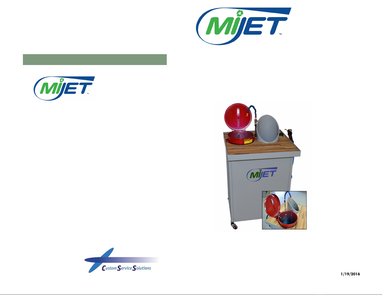
Description
MiJET®is designed to clean parts and capture residue with one easy touch,
keeping the work area and surrounding air clean.
The air nozzle is used to blow residue down into the inlet tube, while simul-
taneously creating suction. This will pull chips and lubricant into the contain-
er below.
The captured residue can be recycled ... saving money on expensive lubri-
cants and help to reclaim more chips instead of covering the floor.
Needed
A MiJET unit comes with a 1/4” FNPT
fitting for connecting to an existing shop
air line. A high–flow quick-connect
adaptor can be attached for ease of
use, however, to ensure a sufficient air
supply we recommend connecting into
the main air supply without any re-
strictions, such as a quick connect.
It is also recommended to utilize a 3/8”
diameter air hose from the main line to
supply the MiJET. A smaller diameter,
coiled air line, or a line that is too long
might not provide an optimum air sup-
ply.
Safety Instructions
Please read user guide carefully before
installing.
Disconnect the air supply if the unit is
taken apart for recycling of coolant,
retrieval of parts, or any other mainte-
nance.
Page 19
U S E R G U I D E
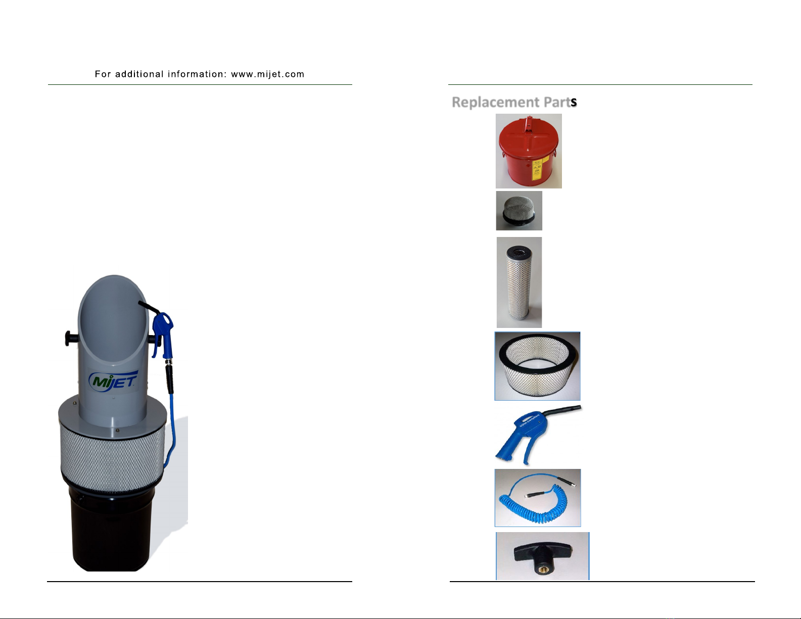
Replacement Parts
13-032 T-Handle Knob
Nylon with Aluminum insert
13-029
Spiral air hose with swivel end
ng
13 . x 1/4" MNPT, 5/16" ID
13-028
Air Nozzle by Prevost, OSHA Compliant
8.0" x 4.25" x 1.0"
15-100
Solvent Dip Container, 3.5 gallon with fusi-
ble link for re damping, 15” x 12.0”
13-006
Custom MiJET Filter, for 12” models only
6” H x 19.25” dia.
Fluid Filter Replacement for Washstaons only.
9.63“ H x 2.63” dia.
15-118
15-119 Basket strainer

Page 18
Oponal Accessories
13-035 Low-Noise Air Nozzle by Silvent
15-104
Non-metallic basket liner
For use inside SS basket to keep so parts
from geng damaged.
*Need to order both the body and the plug for correct connecon
Low-Noise Air Nozzle with Rubber
Tip by Silvent
OSHA compliant
13-071
15-107
Stainless Steel Parts Basket—
Fine Mesh, for 12” dia. MiJET angled top
workstaon and wash staon
13.5” x 7.25” x 9.75”
13-057*
13-058*
High-Flow Quick Disconnect - Body
High-Flow Quick Disconnect - Plug
Page 3
U S E R G U I D E
MiJET Diagram .………………….……........ Page 4
Air Supply Requirements …....…….……........ Page 6
Instructions ..………………………….……. Page 7
Using the Faucet …………..………….……. Page 9
Removing MiJET from Table ………….…..... Page 10
Maintenance ………………….…….……... Page 12
Installing the Air Deflector ………….……... Page 16
Troubleshooting …………………….……... Page 17
Optional Accessories ………….……………Page 18
Replacement Parts ….………………………Page 19
Table of Contents
**NOT FOR USE WITH HIGHLY
FLAMMABLE LIQUIDS**
Inlet
Page 4
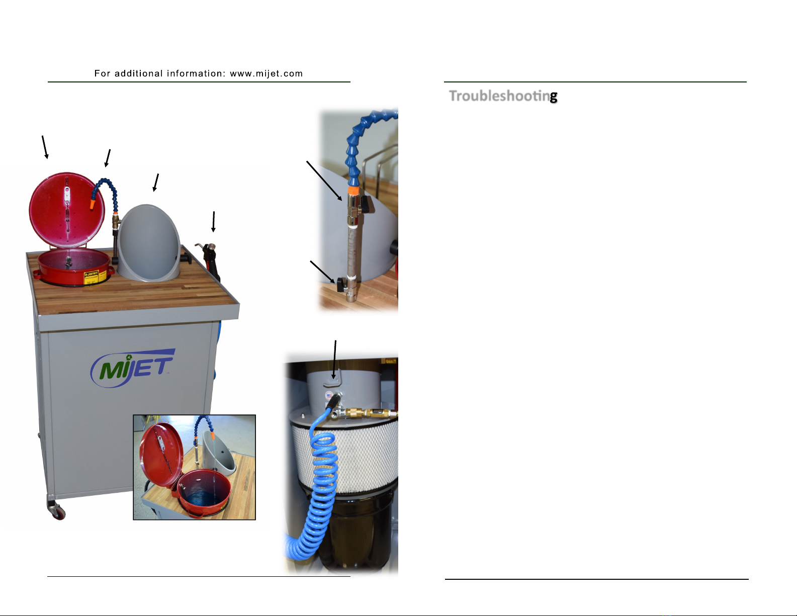
MiJET Diagram
Loc-Line
Faucet
Dip Container
Air nozzle with
trigger handle
On/Off Ball
Valve
Flow Valve
Retainer hook
Troubleshoong
Q: The part is blown off and the air nozzle is not in use, but the
motor runs for an extended amount of time.
A: There are Viton O-rings that need to stay lubricated, try adding air
tool oil, refer to the maintenance steps on page 6.
B: Check for air leaks at air nozzle hose connections and air nozzle it-
self. Replace leaking components if needed. Contact us for replace-
ment air gun.
Q: The air motor sounds like it runs slower than when the unit
was brand new.
A: Try adding air tool oil, refer to the maintenance steps on page 6.
Q: The suction is reduced from when the unit was brand new.
A: Try adding air tool oil, refer to the maintenance steps on page 6.
B: Check filter and if oil-soaked or dirty, it is time to replace the filter.
Contact us for replacement filter.
Q: The blow off pressure has decreased while using the air noz-
zle.
A: Ensure all fittings and connections are correct, if so, try connecting the
MiJET to the air supply line without use of any quick-disconnect fitting.
B: Try connecting an airline from the main air supply to the MiJET with a
large enough diameter (3/8”) air hose to supply enough CFM to the
unit.
C: Try removing the blue air nozzle and replace with the operators’
usual air nozzle often creates familiarity with usual process of blow-
ing off parts.
Page 17
U S E R G U I D E
Page 16
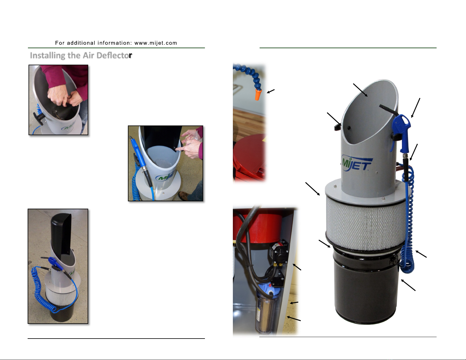
Installing the Air Deector
1. Using a 7/32 Allen key, unscrew
the black screws from each handle,
as seen in Figure 20.
2. Take each screw and handle off of
the unit.
3. Place the air deflector into the
MiJET. Try to line-up the hole
on the air deflector (Figure 21)
with the hole on the MiJET.
4. Insert the screw through the air de-
flector and then through the MiJET.
5. Tighten both screws with the 7/32
Allen key. Hold the black plastic
handle while tightening to ensure
the correct handle orientation of the
T-Handle.
6. Repeat the same procedure for the
second screw on the opposite side.
The final product should look like
the MiJET picture in Figure 22.
Figure 20
Figure 21
Figure 22
Page 5
U S E R G U I D E
Air nozzle with
trigger handle
Air hose
Air inlet—
connect
directly to
air supply
or use high-
flow quick
connect
Carrying
handles
Container
Air filter
Clamping
tabs (not
shown)
Inlet pipe
MiJET Diagram
Changeable
nozzle
Fluid pump
Fluid filter
Fluid filter
housing
Table of contents


