miniDSP UMIK-X User manual


miniDSP Ltd, Hong Kong / www.minidsp.com / Features and specifications subject to change without prior notice 2
Revision history
Revision
Description
Date
0.2
Preliminary
15 March 2020
0.3
Second Preliminary
1 June 2020
0.4
Added screenshots for Mac
8 June 2020
0.5
Updated support links
6 July 2020
0.6
Added 4-channel firmware
21 August 2020

miniDSP Ltd, Hong Kong / www.minidsp.com / Features and specifications subject to change without prior notice 3
TABLE OF CONTENTS
Important Information...................................................................................................................................4
1Product Overview ....................................................................................................................................6
2Hardware Connectivity.............................................................................................................................7
3Installation and Configuration –Windows ..............................................................................................13
3.1 Download ................................................................................................................................................ 13
3.2 USB driver installation............................................................................................................................. 13
3.3 4-channel firmware ................................................................................................................................. 14
3.4 UAC2 Control Panel ................................................................................................................................. 15
4Installation and Configuration –Mac OS X..............................................................................................17
4.1 Download ................................................................................................................................................ 17
4.2 4-channel firmware ................................................................................................................................. 17
4.3 Configuration in Audio MIDI Setup ......................................................................................................... 18
5Room EQ Wizard Multichannel Measurement ........................................................................................19
5.1 Enabling the license................................................................................................................................. 19
5.2 Configuring REW Preferences –Windows............................................................................................... 20
5.2.1 miniDSP ASIO driver ........................................................................................................................ 20
5.2.2 ASIO4ALL.......................................................................................................................................... 21
5.2.3 Selecting the calibration file............................................................................................................ 21
5.3 Configuring REW Preferences –macOS/OS X ......................................................................................... 22
5.3.1 Select input and output................................................................................................................... 22
5.4 Running a multichannel measurement ................................................................................................... 24
6Additional Information ..........................................................................................................................26
6.1 Specifications........................................................................................................................................... 26
6.1.1 USB-A2B interface ........................................................................................................................... 26
6.1.2 UMA-4 Module................................................................................................................................ 26
6.2 Firmware upgrade ................................................................................................................................... 27
6.2.1 Windows.......................................................................................................................................... 27
6.2.2 macOS.............................................................................................................................................. 29
6.3 Obtaining support.................................................................................................................................... 31

miniDSP Ltd, Hong Kong / www.minidsp.com / Features and specifications subject to change without prior notice 4
IMPORTANT INFORMATION
Please read the following information before use. In case of any questions, please contact miniDSP via the
support portal at support.minidsp.com.
Disclaimer/Warning
miniDSP cannot be held responsible for any damage that may result from the improper use or incorrect
configuration of this product. Please read this manual carefully to ensure that you fully understand how to
operate and use this product, as incorrect use or use beyond the parameters and ways recommended in this
manual have the potential to cause damage to your audio system.
Please also note that many of the questions we receive at the technical support department are already
answered in this User Manual and in the online application notes on the miniDSP.com website. So please take
the time to carefully read this user manual and the online technical documentation. Thank you for your
understanding!
Warranty Terms
miniDSP Ltd warrants this product to be free from defects in materials and workmanship for a period of one
year from the invoice date. Our warranty does not cover failure of the product due to incorrect connection or
installation, improper or undocumented use, unauthorized servicing, modification or alteration of the unit in any
way, or any usage outside of that recommended in this manual. If in doubt, contact miniDSP prior to use.
FCC Class B Statement
This device complies with Part 15 of the FCC Rules. Operation is subject to the following two conditions:
•This device may not cause harmful interference.
•This device must accept any interference received, including interference that may cause undesired
operation.
Warning: This equipment has been tested and found to comply with the limits for a Class B digital device,
pursuant to Part 15 of the FCC Rules. These limits are designed to provide reasonable protection. This
equipment generates, uses and can radiate radio frequency energy and, if not installed and used in accordance
with the instructions, may cause interference to radio communications. However, there is no guarantee that
interference will not occur in a particular installation. If this equipment does cause harmful interference to radio
or television reception, which can be determined by turning the equipment off and on, the user is encouraged to
try to correct the interference by one or more of the following measures:
•Reorient or relocate the receiving antenna.
•Increase the separation between the equipment and receiver.
•Connect the equipment into an outlet on a circuit different from that to which the receiver is connected.
•Consult the dealer or an experienced radio/TV technician for help.
Notice: Shielded interface cable must be used in order to comply with emission limits.
Notice: Changes or modification not expressly approved by the party responsible for compliance could void the
user’s authority to operate the equipment.

miniDSP Ltd, Hong Kong / www.minidsp.com / Features and specifications subject to change without prior notice 5
CE Mark Statement
The UMIK-X has passed the test performed according to European Standard EN 55022 Class B.
A Note on this Manual
This User Manual is designed for reading in both print and on the computer. If printing the manual, please print
double-sided. The embedded page size is 8 ½” x 11”. Printing on A4 paper will result in a slightly reduced size.
For reading on the computer, we have included
hyperlinked cross-references throughout the
manual. In addition, a table of contents is
embedded in the PDF file. Displaying this table of
contents will make navigation much easier:
•In Adobe Reader on Windows, click on the
“bookmarks” icon at the left. The table of
contents will appear on the left and can be
unfolded at each level by clicking on the “+”
icons.
•In Preview on the Mac, click on the View
menu and select Table of Contents. The table
of contents will appear on the left and can be
unfolded at each level by clicking on the
triangle icons.

miniDSP Ltd, Hong Kong / www.minidsp.com / Features and specifications subject to change without prior notice 6
1PRODUCT OVERVIEW
Thank you for purchasing a miniDSP UMIK-X distributed microphone array. The UMIK-X consists of one to four
UMA-4 microphone modules and a USB-A2B interface to interface the modules to the computer. Between four
and 16 microphones can therefore be connected. UMA-4 modules are daisy-chained to each other using a single
twisted-pair cable carrying the A2B protocol at 44.1 or 48 kHz.
Applications include environmental monitoring and distributed soundfield measurement. The distributed
omnidirectional microphones in the array allow quick measurement and analysis in applications such as room
and hall equalization and distributed subwoofer tuning.
The USB-A2B interface includes a stereo optical output to simplify generation of test audio signals.
The UMIK-X is compatible with the multi-channel measurement capability of Room EQ Wizard. A license for the
multi-channel upgrade is included with your purchase of the UMIK-X.
Each UMA-4 microphone module is a bare circuit board with no environmental protection. It is
intended for prototyping and indoor use. Outdoor use is not recommended, as exposure to moisture
and dust may damage the modules.
miniDSP Ltd, Hong Kong / www.minidsp.com / Features and specifications subject to change without prior notice 7
2HARDWARE CONNECTIVITY
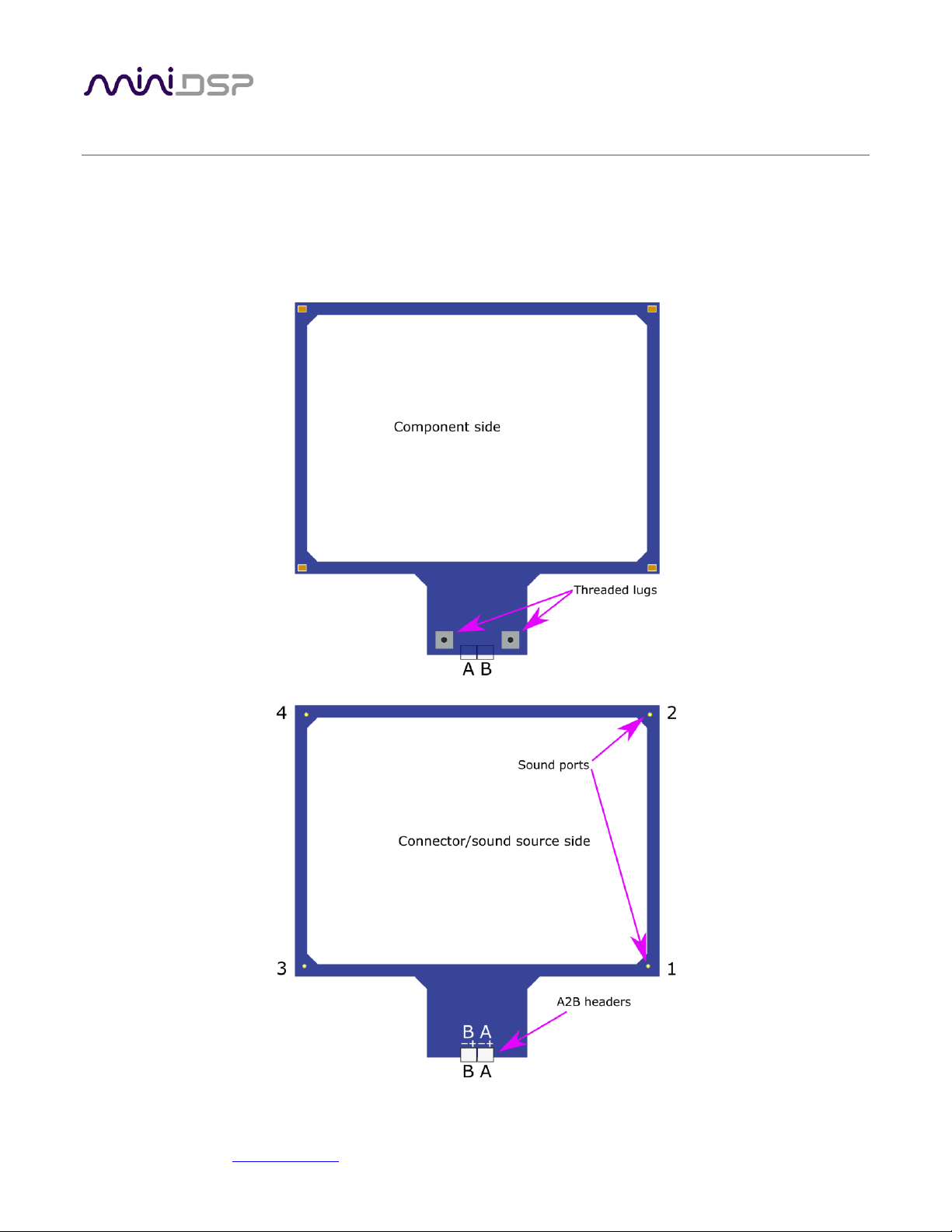
Figure 1 shows the physical structure of the UMA-4 microphone module. Four MEMS microphones are
positioned in a rectangle at approximately 170 mm x 125 mm centers. Two lugs with screw threads are used for
mounting to a microphone stand adapter (supplied). Channel numbering within each module is as shown.
Headers for the two A2B ports A are located as shown. (A third header above one of the threaded lugs is not
intended for end-user access.)
Figure 1. UMIK-X physical structure

miniDSP Ltd, Hong Kong / www.minidsp.com / Features and specifications subject to change without prior notice 8
Figure 2 shows a UMA-4 module with the various parts provided:
•The UMA-4 module itself.
•A twisted-pair cable for connecting modules and the USB-A2B interface.
•Two thumb screws to fasten the UMA-4 to the stand adapter.
•Two thread adapters: ¼” to 3/8” and 3/8” to ½”. These enable the UMA-4 to be mounted to a wide
variety of camera and microphone stands.
•The stand adapter. One or two UMA-4 modules can be mounted to the adapter.
Figure 2. UMA-4 microphone module and provided parts

miniDSP Ltd, Hong Kong / www.minidsp.com / Features and specifications subject to change without prior notice 9
Figure 3 illustrates a single UMA-4 module mounted to the stand adapter, which is in turn mounted onto a
microphone stand. When using a single module, the twisted pair cable to the USB-A2B interface plugs into the
“A” jack as shown.
Figure 3. Single UMA-4 module on microphone stand (connector/sound source side)
miniDSP Ltd, Hong Kong / www.minidsp.com / Features and specifications subject to change without prior notice 10
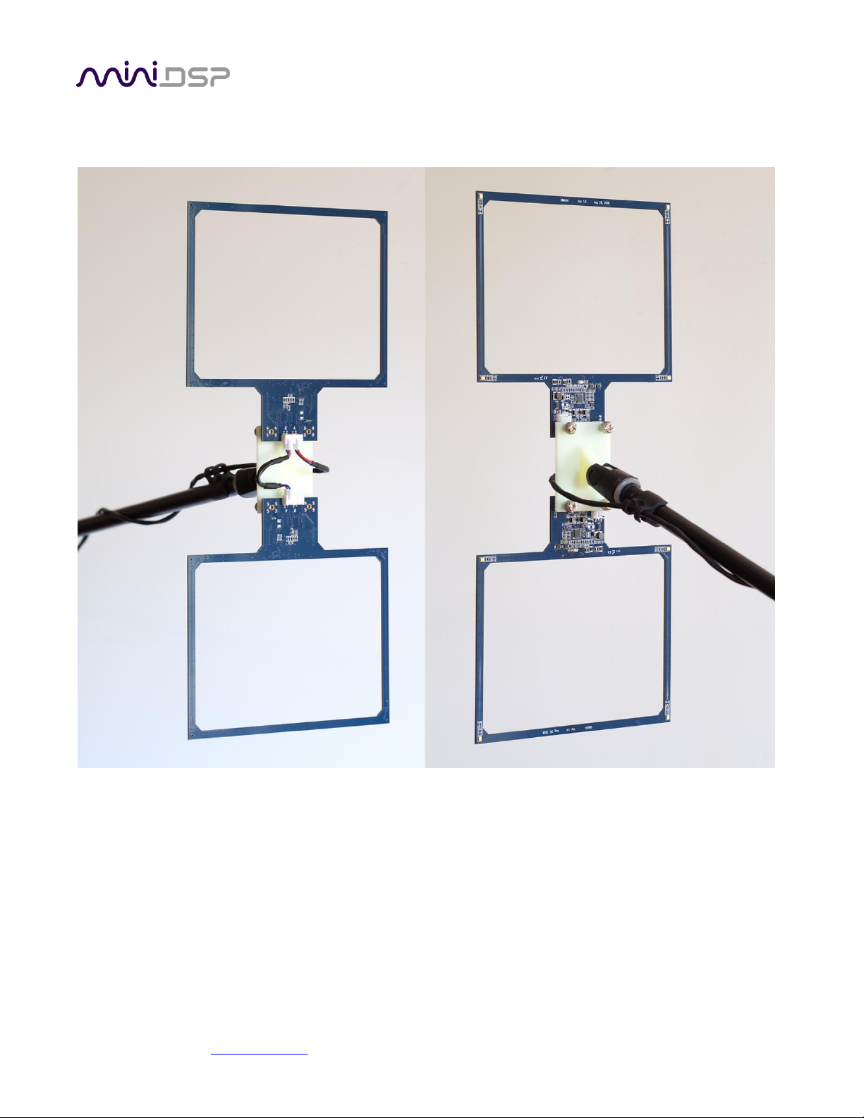
Each pair of UMA-4 modules is provided with a short 8 cm twisted-pair cable. This is used when mounting two
modules onto a single stand, as shown in Figure 4.
Figure 4. Dual UMA-4 modules mounted on a single stand with boom arm
miniDSP Ltd, Hong Kong / www.minidsp.com / Features and specifications subject to change without prior notice 11
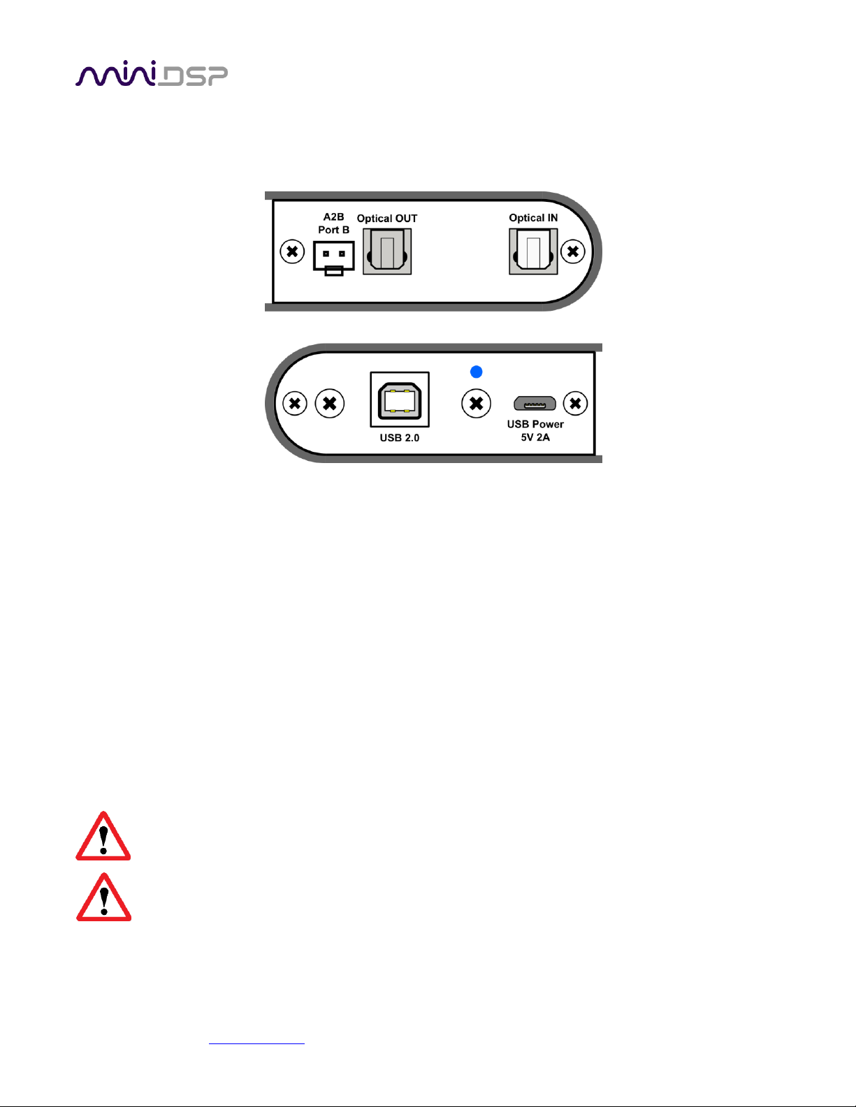
Figure 5 shows the panel connections for the USB-A2B interface. The Optical IN is not active. Optical OUT is
typically used to output test signals. The USB-A2B interface is powered by an external 5V supply through a
micro-USB Type B connector. A 5V 2A USB power supply for this purpose is included with the USB-A2B.
Figure 6 illustrates how the UMIK-X is connected. Note that the power supply is equipped with a USA-style pair
of power pins that fold out from the body. Adapters for UK, EU and AU power are included and can be fitted to
the supply by folding down the pins and sliding the adapter into the slot until it locks.
Here is a standard procedure for getting connected:
1. Connect a free USB (2.0 compatible) port on your computer to the Type B port on the USB-A2B.
2. Connect the “B” A2B port on the USB-A2B to the “A” port on the first UMA-4 module.
3. Connect the “B” port of the first UMA-4 module to the “A” port on the second module (if present).
4. Repeat for the third and fourth modules (if present).
5. Plug in the provided 5V 2A USB power supply to mains power. Connect the USB port on the power
supply to the micro USB power port on the interface.
All microphone modules must be connected before applying power to the USB-A2B interface,
otherwise the modules will not be recognized.
The power supply must supply adequate power to the modules. We recommend using the provided
power supply (5V 2A) or equivalent, and not using e.g. a computer USB port to supply power.
Figure 5. USB-A2B interface


miniDSP Ltd, Hong Kong / www.minidsp.com / Features and specifications subject to change without prior notice 13
3INSTALLATION AND CONFIGURATION –WINDOWS
For use with Windows, the miniDSP driver must be installed. You will also need to download the software
package if there is a firmware upgrade.
3.1 DOWNLOAD
If you purchased your product directly from miniDSP, your software will be available from the User Downloads
section of the miniDSP website when your order ships. You will need to be logged into the website with the
account you created when purchasing to access the download.
If you purchased your product from a miniDSP dealer, you will receive a coupon together with the product.
Redeem this coupon and select the Plugin Group “UMIK-X” at the link below:
•https://www.minidsp.com/support/redeem-coupon
The User Downloads link is visible from the dropdown menu at the top right of the website page:
Navigate to the USB Audio Drivers section and download the zip file under the heading UMIK-X. Unzip the
downloaded file by right-clicking on it and selecting “Extract All...”.
3.2 USB DRIVER INSTALLATION
The USB driver enables Windows to stream audio to the UMIK-X. In addition, it installs a control panel to help
manage the UMIK-X.
To install the driver, go to the WinDrivers folder of the installation download and double-click on the installer:
•miniDSP_UAC2_v4.67.0_2019-08-15_setup.exe
(The version number embedded in the filename may be different.)
We recommend accepting the default installation location. Once the driver installation completes, click the
Finish button.

miniDSP Ltd, Hong Kong / www.minidsp.com / Features and specifications subject to change without prior notice 14
3.3 4-CHANNEL FIRMWARE
By default, all channels of each UMA-4 modules are provided to the computer over USB, for a total of up to 16
channels. In some applications, it is desired to produce only a single channel from each UMA-4, for a total of up
to 4 channels.
To install this version of the firmware, follow the procedure starting on page 27. Choose the firmware file UMIK-
X-4CH_v1.2.bin to load into the UMA-4. (The version number “v1.2” may be different.)
All other procedures to use the UMIK-X in this manual are the same, except that (if you have four UMA-4
modules) REW or other measurement software will see only four channels from the UMIK-X.

miniDSP Ltd, Hong Kong / www.minidsp.com / Features and specifications subject to change without prior notice 15
3.4 UAC2 CONTROL PANEL
To configure the UMIK-X, open the miniDSP UAC2 Control Panel (from Start Menu -> miniDSP Ltd). It has several
tabs.
Status
This tab shows the current sample rate of the UMIK-X. This setting cannot be changed in the Control panel, but
simply reflects the current sample rate of the UMIK-X.
Format
This tab shows the input and output channel word lengths:


miniDSP Ltd, Hong Kong / www.minidsp.com / Features and specifications subject to change without prior notice 17
4INSTALLATION AND CONFIGURATION –MAC OS X
Mac OS X / macOS has native support for USB Audio class 2.0 devices, so no driver installation is required. You
may need to download the software package to update firmware.
4.1 DOWNLOAD
If you purchased your product directly from miniDSP, your software will be available from the User Downloads
section of the miniDSP website when your order ships. You will need to be logged into the website with the
account you created when purchasing to access the download.
If you purchased your product from a miniDSP dealer, you will receive a coupon together with the product.
Redeem this coupon and select the Plugin Group “UMIK-X” at the link below:
•https://www.minidsp.com/support/redeem-coupon
The User Downloads link is visible from the dropdown menu at the top right of the website page:
Navigate to the USB Audio Drivers section and download the zip file under the heading UMIK-X. Unzip the
downloaded file by double-clicking on it.
4.2 4-CHANNEL FIRMWARE
By default, all channels of each UMA-4 modules are provided to the computer over USB, for a total of up to 16
channels. In some applications, it is desired to produce only a single channel from each UMA-4 for a total of up
to 4 channels.
To install this version of the firmware, follow the procedure starting on page 29. Choose the firmware file UMIK-
X-4CH_v1.2.bin to load into the UMA-4. (The version number “v1.2” may be different.)
All other procedures to use the UMIK-X in this manual are the same, except that (if you have four UMA-4
modules) REW or other measurement software will see only four channels from the UMIK-X.
miniDSP Ltd, Hong Kong / www.minidsp.com / Features and specifications subject to change without prior notice 18
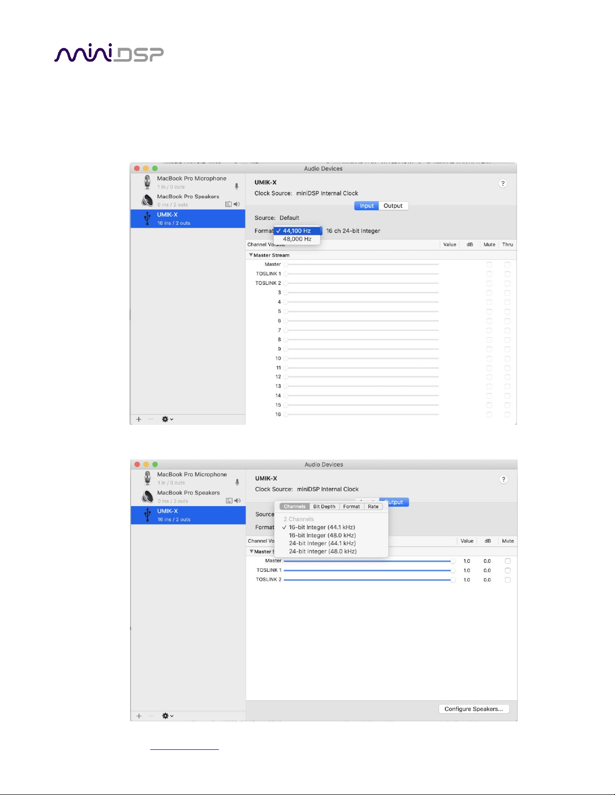
4.3 CONFIGURATION IN AUDIO MIDI SETUP
Open the program Audio MIDI Setup (in Applications->Utilities). Click on the device UMIK-X that appears in the
list on the left. This will display the input and output channels. The Format drop-down menu will show the
supported sample rates. For the input channels:
For the output channels:

miniDSP Ltd, Hong Kong / www.minidsp.com / Features and specifications subject to change without prior notice 19
5ROOM EQ WIZARD MULTICHANNEL MEASUREMENT
The UMIK-X is provided with a license for the multichannel measurement feature of Room EQ Wizard (REW).
5.1 ENABLING THE LICENSE
To enable your license, drop down the Upgrades menu and select Multichannel measurement. Paste in your
license code.
You will need to quit REW and start it again for the license to take effect:
miniDSP Ltd, Hong Kong / www.minidsp.com / Features and specifications subject to change without prior notice 20
5.2 CONFIGURING REW PREFERENCES –WINDOWS
To use the UMIK-X, open the Preferences window (the wrench/spanner icon at top right). You will need to
decide on how to allow REW to output test signals as well as to select the UMIK-X for audio input.
5.2.1 miniDSP ASIO driver
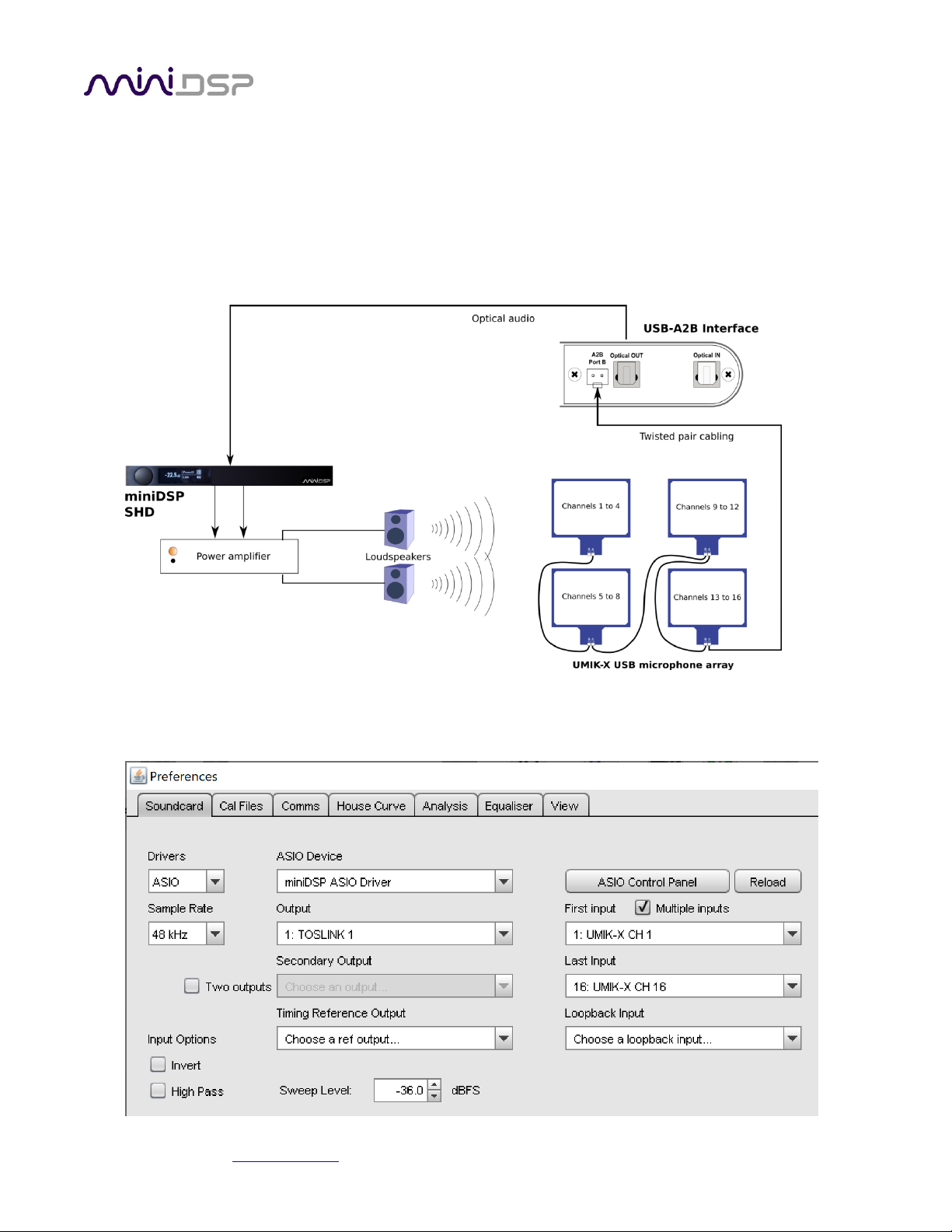
The A2B interface has a standard optical stereo output (TOSLINK). The simplest method of sending test audio
from REW is to connect this optical output to a device that has an optical input. For example:
In this case, you can use the miniDSP ASIO driver directly. In the REW Preferences window, first select ASIO
under Drivers (top left of Preferences screen). Then select the miniDSP ASIO Driver under ASIO Device. Select
the input and output channels as shown:
Table of contents


