1
MITSUBISHI CT 29BV1 BD
Recommended Safety Parts
Item Part No. Descri tion
Load Dressing
255P941040 CRT A68EDG038X301
T551 MAIN 334P243030 TRANS-FLYBACK
T901 MAIN 350P663020 TRANS-POWER
409P564070 ADG-COIL
R352 MAIN 103P378060 R-FUSE 1/4W 3.3-J
R353 MAIN 103P378060 R-FUSE 1/4W 3.3-J
R3A11 AUDIO-PWR 103P378060 R-FUSE 1/4W 3.3-J
R3A12 AUDIO-PWR 103P378060 R-FUSE 1/4W 3.3-J
R3B01 AUDIO-PWR 103P378060 R-FUSE 1/4W 3.3-J
R3B02 AUDIO-PWR 103P378060 R-FUSE 1/4W 3.3-J
R512 MAIN 103P442020 R-FUSE-METAL 1W 560-K/J
R513 MAIN 103P398040 R-FUSE 1/2W 2.2-J
R514 MAIN 103P397090 R-FUSE 1/2W 0.82-J
R516 MAIN 103P397090 R-FUSE 1/2W 0.82-J
R5M1 MAIN 109P913050 R-COMPOSITION 1/2W 68M-J
R671 VM/CRT 103P448050 R-FUSE-METAL 1W 27-K/J
R6B1 VM/CRT 103P370010 R-FUSE 1/4W 10-J
R6B4 VM/CRT 103P392050 R-FUSE 1/2W 10K-J
R6B6 VM/CRT 103P370050 R-FUSE 1/4W 22-J
R6B7 VM/CRT 103P370010 R-FUSE 1/4W 10-J
R6B8 VM/CRT 103P392050 R-FUSE 1/2W 10K-J
R981 MAIN 109P913050 R-COMPOSITION 1/2W 6.8M-J
R982 MAIN 109P913050 R-COMPOSITION 1/2W 6.8M-J
R992 POWER-SUB 109P91 1090 R-COMPOSITION 1/2W 470K-J
RP991 POWER-SUB 265P071 050 POSISTOR PTH451 041 BG180N
J601 VM/CRT 4490126010 CRT SOCKET
F991 POWER-SUB 283D047040 FUSE T2A
P0951 MAIN 268P068010 PHOTOCOUPLER TCDT1124G
Z552 MAIN 299P193010 PROTECTOR 2000
Z951 MAIN 299P193030 PROTECTOR 3150
Z952 MAIN 299P193070 PROTECTOR 5000
Z953 MAIN 299P193000 PROTECTOR 1600
920A427002* ASSY-PWB-MAIN Later models *
H92A002001* ASSY-PWB-MAIN Early models *
9300899011 ASSY-PWB-VM/CRT
9300900005 ASSY-PWB-POWER-SUB
9300901003 ASSY-PWB-LED
9300904004 ASSY-PWB-AUDIO-PWR
9300909001 ASSY-PWB-TEXT
9300911017 ASSY-PWB-DOLBY
2460162010 AC-POWERCORD/U K-PLUG
7000609080 ASSY BACK COVER
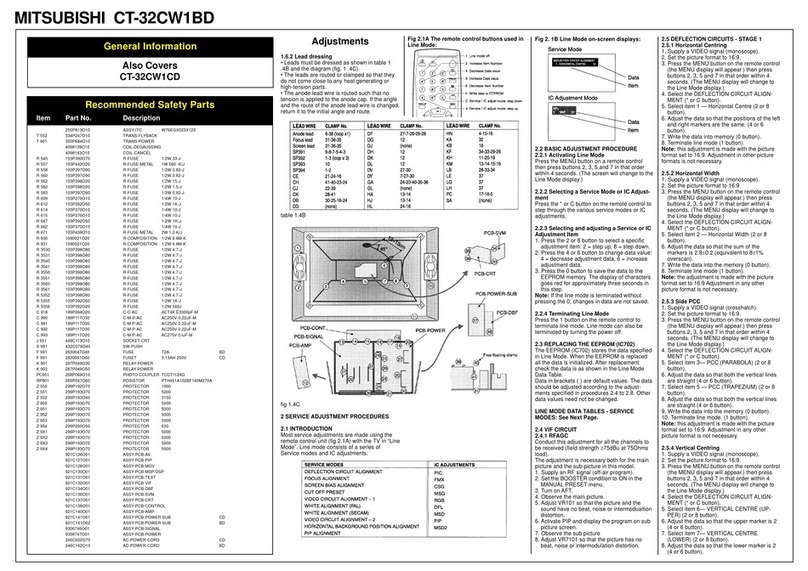
1.4.2 Lead dressing
Leads must be dressed as shown in table 1 .4B
and the diagram (fig. 1.4C) below. The leads are
routed or clamped so that they do not come
close to any heat generating or high-tension
parts. The anode lead wire is routed such that
no tension is applied to the anode cap. If the
mounting angle of the anode cap and the route
of the anode lead wires are changed, return
them to the initial angle and route.
CLAMP No WIRES CLAMPED
1 KB, KK
2 DA, DM
3DM
4 DA, DD, DE, DF (3+4)
5DD
6 DA (looped), KD
7 DY (Loop the lead twice)
8 LB, BA (Loop the lead twice)
9 KD, SC, GA (Loop the lead)
10 LB (Loop the lead twice), SB, Focus
11 Anode lead
12 BA, DF(1+2)
table 1.4B Lead-dressing table.
table 1.4C Lead-dressing diagram.
Adjustments
2.1 introduction
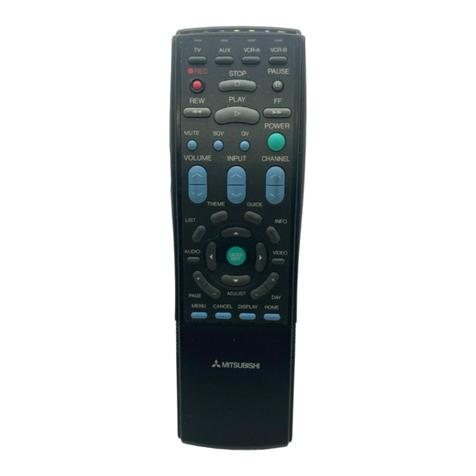
Most service adjustments to these models are
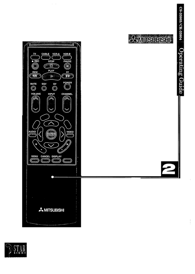
made using the remote control (figure 2.1A) with
the TV in service mode. The adjustment data is
stored in an EEPROM.
NOTE: The software in the microcontroller
IC701 may be either of 2 versions -EE3 or
EE3W. EE3 software is used in IC701 part no.
274P755010, EE3W software is used in IC701
part no. 274P755040.
The actual software in use is shown on the
Options adjustment display - see the next
section.
2.1.1 Basic adjustment procedure
1.Turn the power on and enter service mode -
either (EE3) press the Service switch (S701,
next to the aerial socket) and then button
“9”
within 5 seconds (EE3W) press the MENU
button to display the MAIN MENU then
immediately key-in 2-3-5-7.
2. Press the “*” button to toggle between the
VCJ or OPTION adjustment display (figs. 2.1
B, C, D and E).
3. Press buttons “2” or “8” to increase or
decrease the adjustment code number.
4. Press buttons “6” or “4” to increase or
decrease the data value.
5. After making adjustments, press button “0’, to
write the adjustment data to the EEPROM. To
cancel a change, press button “1’, and all
data adjusted since the last EEPROM write
will be reset.
2.2 INITIALISING THE EEPROM
If you have replaced the EEPROM (IC702) or if
for any reason the adjustment data has become
corrupted it will be necessary to initialise the
EEPROM.
2.2.1 Initialising the EEPROM
1. If necessary, switch off by the Main switch.
2. (EE3) Hold in the service switch (S701, next
to the aerial socket) or (EE3W) connect pin
55 of IC701 to ground via a 1000 resistor
while switching on by the Main switch.
3. (EE3) Release the service switch after 3
seconds or (EE3W) remove the shorting
resistor.
4. Switch off by the Main switch. The EEPROM
data values have now all been reset to their
initial default values.
5. Switch on by the Main switch. (EE3) Press
the Service switch and then button 9 on the
remote control within 5 seconds to enter
service mode (EE3W) press MENU then key
in 2-3-5-7.
6. Press the “*” button to select the OPTIONS
adjustment display.
7. Press buttons 2 or 8 to select the adjustment
code.
8. Adjust the data value for each code as shown
in table 2.2A below using buttons 2 or 4:
(other codes may be displayed but are not
used) EE3 software:
CODE: SETTING:
TUN 1
SAT 0
AUD 0
ATS 1
STD 1
SYS 2
AVI 2
SPK 0
ABG 12
Al 08
AL 06
CODE: SETTING:
ADK 08
MNP 70
FFT 1
VOL 74
HYP 1
SCP 20
FMP 23
EE3W software:
CODE: SETTING:
TUN 1
SAT 0
AUD 0
ATS -
STD 1
SYS 2
AVI 2
AUD -
SPK 1
MNP 70
FFT -
VOL 74
HYP 1
SCP 20
FMP 23
DBY 1
WID 0
table 2.2A Data values for the OPTIONS
adjustments.
9. Press the 0 button to write the changes to the
EEPROM.
10.Press the * button to select the VCJ adjust-
ment display.
11.Press buttons 2 or 8 to select the adjustment
code.
12.Adjust the data value of each code using
buttons 2 or 4 according to table 2.2B below:
EE3 software
CODE: 11 19 1B
VALUE: 001 -1 -13
EE3W software
CODE: SHA HPT HPX
VALUE: 001 -1 -13
table 2.2B Data values for the VCJ adjustments.
13.Press the “0,” button to write the changes to
the EEPROM.
2.2.2 OPTION and VCJ code descriptions.
VCJ
CODE FUNCTION CODE
(EE3) (EE3W)
00 V-AMP-50 0 VH5
01 V-B-CORRECTION 1 VBC
02 P-AMP-50 2 PA5
03 P-TILT 3 PT5
04 V-LIN 4 LIN
05 C-CORRECTION-50 5 CC5
06 H-AMP 6 HW5
07 16x9-SW.RGB-MATRIX 0 MTX
08 V-SHIFT- 50 7 VS5
09 H-PHASE-5O 13 HP5
0A BLUE DRIVE 1 BDR
0B GREEN DRIVE 2 GDR
0C RED DRIVE 3 RDR
0D CONTRAST 4 CON
0E BRIGHT 5 BRI
0F COLOUR SATURATION 6 COL
10 NTSC TINT 8 TNT
11 SHARPNESS 7 SH
12 PAL-LUMA-DELAY 12 PCD
13 SECAM-LUMA-DELAY 11 SCD
14 V-AMP-60 8 VH6
15 P-AMP-60 9 PA6
16 H-AMP-60 12 HW6
17 V-SHIFT-60 13 VS6
18 H-PHASE-60 14 HP6
19 H-PHASE-TEXT 15 HPT
1A H-PHASE-SECAM 16 HPS
1B H-PHASE-RGB 17 HPX
1C P-AMP-16: 9 18 PA9
1D 358 NTSC-LUMA-DELAY -
1E 443 NTSC-LUMA-DELAY -
- NTSC (358 & 443) CHROMA DELAY 10 NTD
- BG CHROMA DELAY OFFSET 9 BGD
- P-AMP-60 9 PA6
- P-TILT-60 10 PT6
- C-CORRECTION-60 11 CC6
- TOP-BLANKING-50 14 TB5
- BOTTOM-BLANKING-50 15 BB5
- H-BLANKING-WIDTH-50 16 BW5
- H-BLANKING-PHASE-50 17 BP5
- TOP-BLANKING-60 18 TB6
- BOTTOM-BLANKING-60 19 BB6
- H-BLANKING-WIDTH-60 20 BW6
- H-BLANKING-PHASE-60 21 BP6
OPTIONS
CODE FUNCTION CODE
(EE3) (EE3W)
TUN TUNER TYPE TUN
SAT SATELLITE ENABLE SAT
AUD AUDIO SYSTEM AUD
ATS AUTOTUNING SORT ATS
STD RECEPTION STANDARD STD
SYS COLOUR SYSTEM SYS
AVI NO. OF AV INPUTS AVI
AVD AV DUBBING AVD
EEX CHASSIS TYPE -
SPK SPEAKER SW ENABLED SPK
EEP EEPROM SIZE -
ABG AGC GAIN – BG -
Al AGC GAIN-I -
AL AGC GAIN-L -
ADK AGC GAIN-DK -
MNP NICAM PRESCALE MNP
TXT TELETEXT TYPE -
FFT FAST/TOP TEXT FFT
VOL VOLUME PRESCALE VOL
HYP HYPERSOUND HYP
SCP SCART PRESCALE SCP
FMP FM PRESCALE FMP
- DOLBY DBY
- WIDE SCREEN WID
2.3 VIF CIRCUITS
2.3.1RF AGC
VR101 (adjacent to the tuner)
1. Connect an RE signal such as an off-air
broadcast.
2. Check the AFT is on for the current channel.
3. Adjust VR101 so that the picture and sound
exhibit no noise, beat or intermodulation
distortion.
2.3.2 SIF OFFSET
VR 102 (near IC101)
1. Connect an RE Crosshatch pattern signal
with NO sound modulation
2. Set the Volume control to about 3/4 of
maximum.
3. Adjust VR102 to obtain minimum noise.
2.4 DEFLECTION CIRCUITS
2.4.1Important notes
Before making any adjustments, if you have
changed the CRT, FLYBACK TRANSFORMER
or made any changes in the deflection circuits;
adjust the CRT bias as described in 2.6.1 steps
1 ~ 4.
Check the VERTICAL BREATHING CORREC-
TION as follows:
1. Select the VCJ adjustment display.
2. Set the adjustment code to 01 (1 VBC) with
buttons “2” or “8” on the remote control.
3. If necessary, adjust the data value to “-31”
using buttons “4’ or “6’ on the remote control.
2.4.2 Horizontal centre
Code: 09 (13 HP5) [H-PHASE-50]
1. Connect a VCR and play a PAL-Monoscope
alignment tape.
2. Select the VCJ adjustment display.
3. Set the adjustment code to 09 (13 HP5) with
buttons “2” or “8” on the remote control.
4. Adjust the horizontal position with buttons “4’
or “6” on the remote control.
2.4.3 Horizontal width
Code: 06 (6 HW5) [H-AMP]
1. Connect a VCR and play a PAL-Monoscope
alignment tape.
2. Select the VCJ adjustment display.
3. Set the adjustment code to 06 (6 HW5) with
buttons “2” or “8” on the remote control.
4. Adjust horizontal width with the buttons “4” or
“6” on the remote control.
2.4.4 East-West PCC
Code: 05 (5 CC5) [CORNER CORRECTION-50]
Code: 03 (3 PT5) [PARABOLA TILT]
Code: 02 (2 PA5) [PARABOLA AMP-50]
1. Connect an RF PAL Crosshatch signal.
2. Select the VCJ adjustment display.
3. Set the adjustment code to 05 (5 CC5) with
buttons “2” or “8” on the remote control.
4. Adjust the data value to “-25” with buttons “4”
or “6” on the remote control.
5. Set the adjustment code to 03 (3 PT5) with
buttons “2” or “8” on the remote control.
6. Watching the second vertical line in from both
sides of the screen (figure 2.4A), make any
upper and lower distortion symmetrical using
buttons “4” or “6” on the remote control.
7. Set the adjustment code to 02 (2 PA5) with
buttons “2”or “8” on the remote control.
8. Adjust the straightness of both vertical lines
(figure 2.4B) using buttons “4” or “6” on the
remote control.
9. Repeat steps 1 to 8 above if necessary.
10.Connect a VCR and play a PAL-Monoscope
alignment tape.
11.Make sure the horizontal width and horizon-
tal centre are correct. If necessary readjust
Horizontal Centre 09 (13 HP5) and Horizontal
Width 06 (6 HW5) again.

