Mobicom Telematics G102 User manual

Mobicom Telematics –G102 User Guide
1/ 18
Copyright © 2018 Shenzhen Mobicom Telematics Co.,Ltd. All rights reserved.
G102 User Guide
V2.3
Revision Date: 06/15/2018
Shenzhen Mobicom Telematics Co.,Ltd Tel: + 86 755 8450 8126
RM602,Xichuangcheng,No.144,Zhiwuyuan Road, Email: sales@mobicomtracking.com
Longgang District, Shenzhen,China Website: http://www.mobicomtracking.com

Mobicom Telematics –G102 User Guide
2/ 18
Copyright © 2018 Shenzhen Mobicom Telematics Co.,Ltd. All rights reserved.
Contents
Contents....................................................................................................................................................................... 2
1 Copyright and Disclaimer.......................................................................................................................................... 3
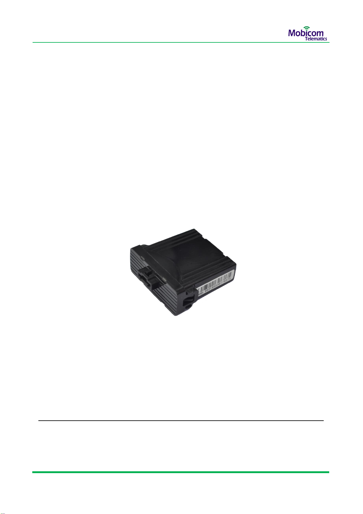
2 Product Overview ..................................................................................................................................................... 3
3 Product Functions..................................................................................................................................................... 4
4 Specifications ............................................................................................................................................................ 5
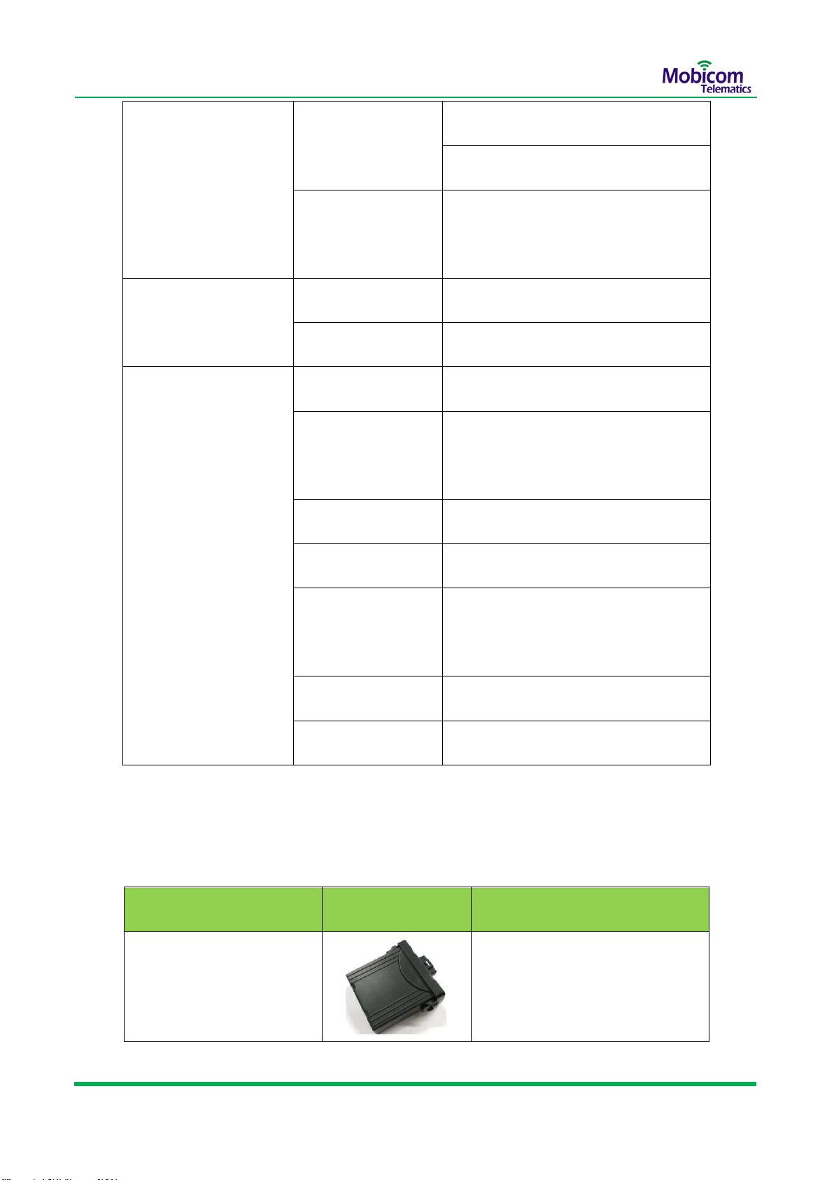
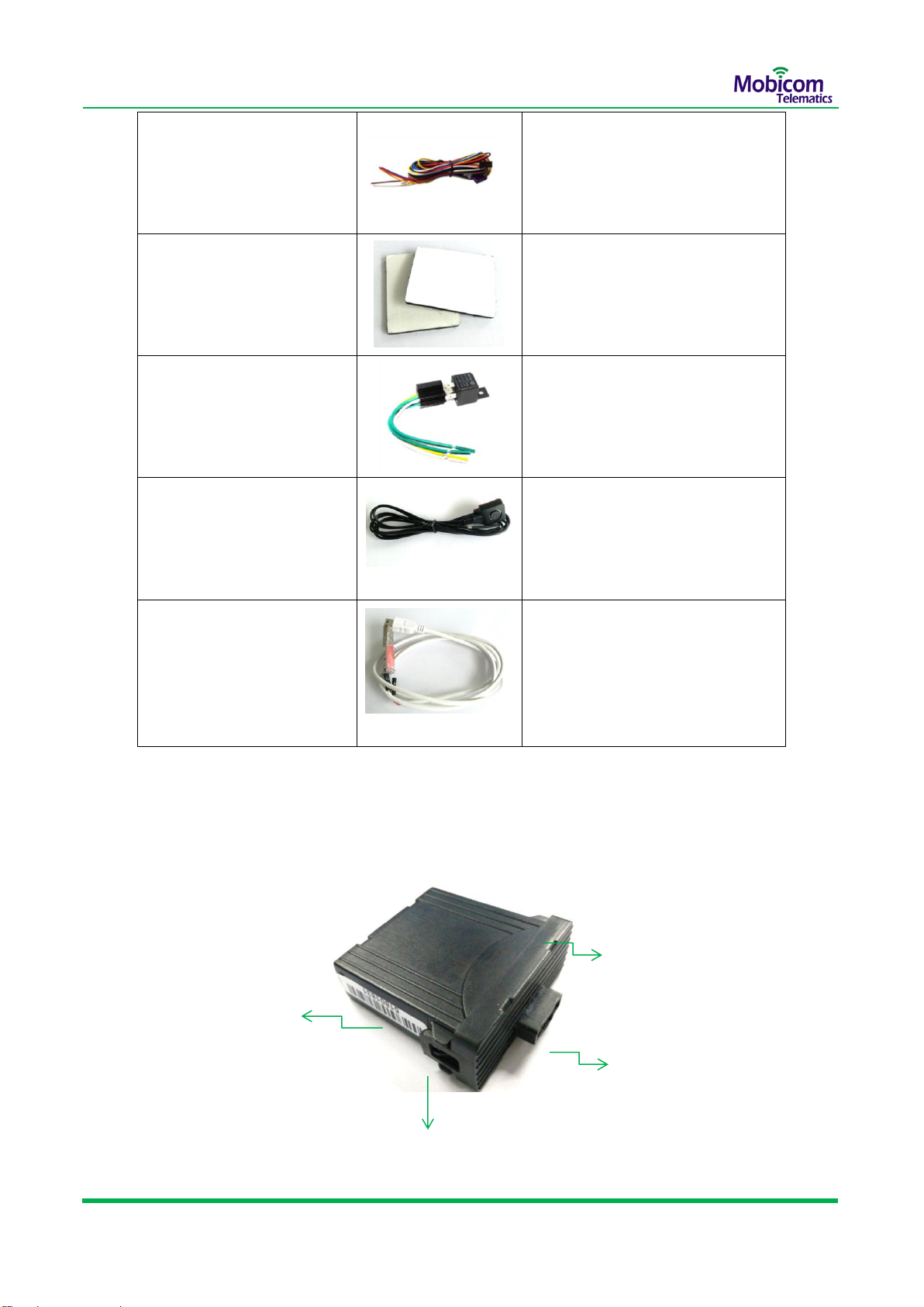
5 Standard Package and Optional Accessories ............................................................................................................ 6
6 Appearance and Structure........................................................................................................................................ 7
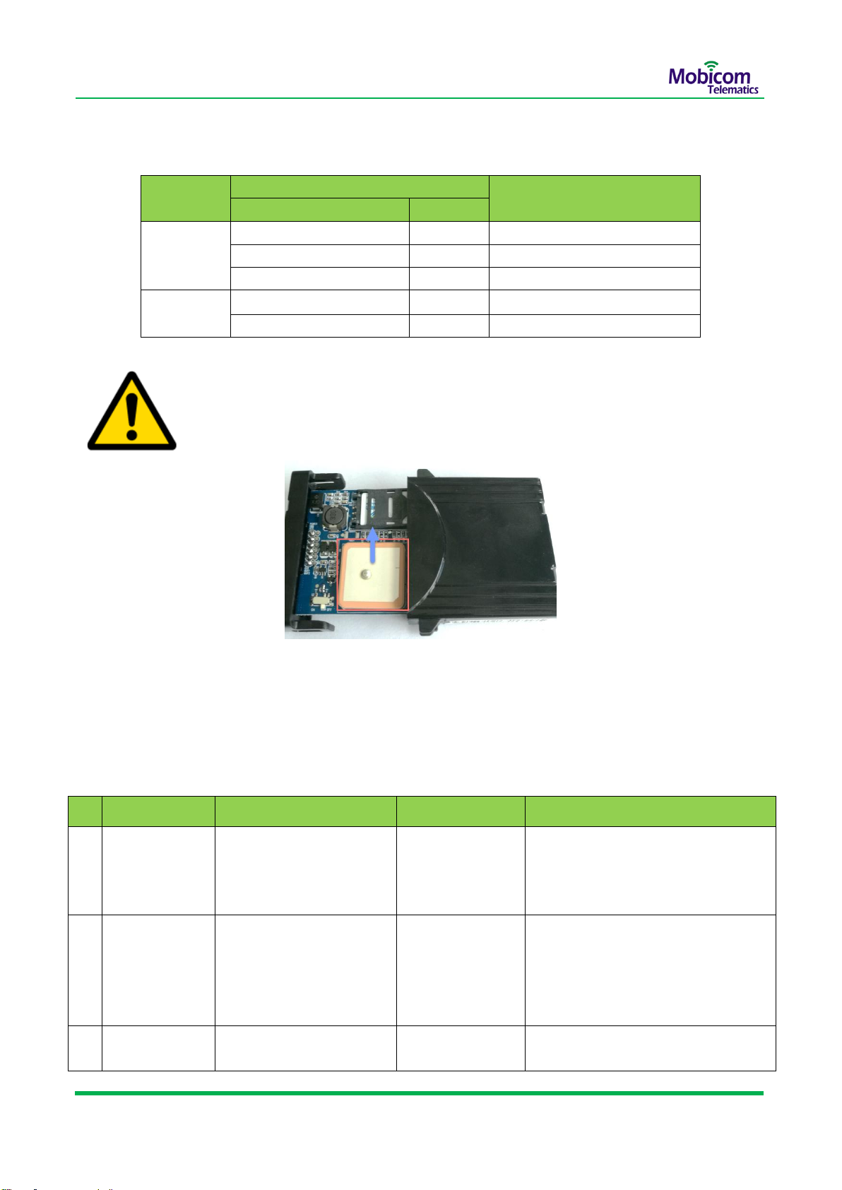
7 First Use .................................................................................................................................................................... 8
7.1 Insert SIM Card .............................................................................................................................................. 8
7.2 Power on the device ...................................................................................................................................... 9
7.3 LED light Indicators ...................................................................................................................................... 10
7.4 Initializing Device Parameters via SMS command ....................................................................................... 10
8 Tracking the device in Mobicom GPS system.......................................................................................................... 12
8.1 Principle of communication ......................................................................................................................... 12
8.2 Get the login ID............................................................................................................................................ 12
8.3 Login Software Platform .............................................................................................................................. 12
9 Installing Device in Vehicle...................................................................................................................................... 13
9.1 Wire harness definition................................................................................................................................ 14
9.2 Connect the Power wires............................................................................................................................. 15
9.3 Connect Digital Input –Ignition .................................................................................................................... 15
9.4 Connect Digital Input –SOS button .............................................................................................................. 16
9.5 Connect Digital Output –OUT1-Fuel pump control ..................................................................................... 16
9.6 Mounting the device.................................................................................................................................... 16
10 Warranty Terms..................................................................................................................................................... 17
Contact Us.................................................................................................................................................................. 18

Mobicom Telematics –G102 User Guide
3/ 18
Copyright © 2018 Shenzhen Mobicom Telematics Co.,Ltd. All rights reserved.
1 Copyright and Disclaimer
Copyright © 2018 Mobicom Telematics Co.,Ltd All rights reserved. Reproduction, transfer, distribution
or storage of part or all of the contents in this document in any form without the prior written permission
of Mobicom Telematics is prohibited.
All contents in this manual are accurate, however, with continuous research and development, we
might update the manual from time to time. The manual which you are reading is reflecting of present
state of art of the products described therein, we have endeavored to give a description that is as
complete and clear as possible in order to make it easy for you to use our products. There might be
some contents described inaccurate technical expression, with the rapid development of technology,
we reserve the rights to incorporate technical alterations and developments without separate notice in
advance.
Mobicom Telematics is not liable for any loss or injury caused by using or referencing to any products.
2 Product Overview
The G102 is a Mini GPS tracker designed for a wide range of vehicle tracking application. It has baisc
I/O interfaces that can be used for GPS vehicle tracking. It’s internal GPS antenna has superior
sensitivity and fast time to be located. It can be monitored in real time or periodically tracked by a
backend server and mobile devices.

Mobicom Telematics –G102 User Guide
4/ 18
Copyright © 2018 Shenzhen Mobicom Telematics Co.,Ltd. All rights reserved.
3 Product Functions
Items
Functions
Communication
Location Data transmitting-GPRS(TCP/UDP)
Commands- SMS/GPRS/Serial port
Position Tracking
Real time location monitoring/querying
Track by moving( time interval)
Track by parking(time interval)
Track by distance
Cornering report
GPS Mileage
GPS Mileage report/GPS mileage coefficient adjustable
Geo-fence
25 rectangle Geo-fences
Alarm(Event)
SOS alarm (SMS/GRPS)
Main Power supply cut off(SMS/GRPS)
Ignition On report(GPRS)
Over Speed alarm(GPRS)
Geo-fence alarm(GPRS)
Towing alarm(GPRS)
Harsh Braking alarm(GPRS)
Harsh Acceleration alarm(GPRS)
I/O
3 digital input (Ignition detecting, SOS button,Input3-reserved)
1 digital output- fuel pump /engine circuit cut

Mobicom Telematics –G102 User Guide
5/ 18
Copyright © 2018 Shenzhen Mobicom Telematics Co.,Ltd. All rights reserved.
Buffer
Data in Buffer when in GPRS blind area
Initialization
Initialize tracker’s Parameters via SMS/GPRS/Serial port
Upgrading
upgrading firmware via OTA or Serial port
Waterproof
IP66
4 Specifications
Items
Specifications
Gift Box Dimension
120*120*50mm
Tracker Dimension
66*60*25 mm
Tracker Color
Black
Weight
Tracker weight
0.1kg
Total package
0.21kg
Power Supply
DC 9V -- 55V
Working current
40 mA(DC 12V)
Back-up battery
Built-in 160mAh, support 1 hour working when fully charged.
(160 to 450mAh customized)
Operating temperature
-25℃-- 75℃
Operating humidity
5% -- 95%
LED indicator
Green led and Red led light indicates GPS and GSM status
respectively
Power Switch
1 Backup battery switch on Mainboard
I/O Port
3 digital inputs
Ignition detecting –positive trigger

Mobicom Telematics –G102 User Guide
6/ 18
Copyright © 2018 Shenzhen Mobicom Telematics Co.,Ltd. All rights reserved.
SOS detecting-negative trigger
Input3 (Reserved)- positive trigger
1 digital output
Fuel pump/engine circuit cut- Output
GND (connect to a normal close relay)
GSM Module
Chipset
FIBOCOM G510
Frequency
850MHz/900MHz/1800MHz/1900 MHz
GPS Module
Chipset
SKYLAB SKG12BL
Positioning
accuracy
< 5m (95%)
Cold start time
< 23s(in average)
Warm start time
< 3 s (in average)
Acquisition
Sensitivity
-148dbm
Acquisition channel
66-channel
GPS Frequency
1575.42 MHz
5 Standard Package and Optional Accessories
Name
Picture
Standard/Optional Parts
Main unit
Standard

Mobicom Telematics –G102 User Guide
7/ 18
Copyright © 2018 Shenzhen Mobicom Telematics Co.,Ltd. All rights reserved.
Wire harness
Standard
Magic tape
Standard
Relay
Standard
SOS button
Standard
Mini-USB Configuration
cable
Optional
6 Appearance and Structure
Side View
Power and I/O wires Port
p
o
r
t
Snap Joint
p
o
r
t
Snap Joint
p
o
r
t
IMEI
p
o
r
t

Mobicom Telematics –G102 User Guide
8/ 18
Copyright © 2018 Shenzhen Mobicom Telematics Co.,Ltd. All rights reserved.
Internal View
Internal View Reverse
7 First Use
7.1 Insert SIM Card
SIM card Slot
p
o
r
t
Backup Battery Switch
p
o
r
t
Cover
p
o
r
t
Mini-USB Port
p
o
r
t
Internal GPS antenna
p
o
r
t
SIM card Slot
p
o
r
t
Backup Battery Switch
p
o
r
t
Cover
p
o
r
t

Mobicom Telematics –G102 User Guide
9/ 18
Copyright © 2018 Shenzhen Mobicom Telematics Co.,Ltd. All rights reserved.
Operation Steps:
⚫Open the Case by tweezers, Pull out the mainboard from the case.
⚫Open the SIM card slot
⚫Insert the Mini(Standard) SIM card into the card slot with its gold-plated contacts facing towards the
Printed Circuit Board (PCB)
⚫Slide the SIM card holder to the right to lock it in place
⚫Do not forget to turn on the battery switch before putting the mainboard back in its metal casing.
➢Ensure that SIM card’s SMS/GPRS Network service are available .
➢Ensure that the phone card PIN lock has been closed properly.
➢The backup battery can be charged when connected External Power supply.
7.2 Power on the device
Connect the Power cable(red) and ground wire(black) to the positive and negative electrodes of the
vehicle battery respectively.
➢Detailed wire harness definition .Refer to 9.1 wire harness definition
➢If you tested G102 device at office, It’s better use the AC to DC Power supply as
below picture:

Mobicom Telematics –G102 User Guide
10 / 18
Copyright © 2018 Shenzhen Mobicom Telematics Co.,Ltd. All rights reserved.
7.3 LED light Indicators
Note: To get a good effect of GPS signal in vehicle installation, please let the Internal
GPS antenna side face to SKY horizontally as below picture:
7.4 Initializing Device Parameters via SMS command
G102 can be configured via SMS. Refer to the command list as below:
No.
Function Name
SMS Command Content
Reponse from G102
Description
1
Set the authorized
SIM number
*SPJLX*P:753869*S:13012345678
,13112345678,13212345678,#
XXX,XXX,XXX, set ok
(max: 3 phone numbers)
2
Set server IP/Port
*SPJLX*P:753869*U:211.153.134.
122,6666,1,#
Reply content is “IP” “Port”, Server IP
Address:211.153.134.122 Port:6666
Transfer type: 0: UDP 1: TCP
Note:
Please get Server IP and Port from Mobicom
Technical support engineer.
3
Set APN
*SPJLX*P:753869*A:CMNET,USE
R,PWD#
if no user name and password.the SMS
is: *SPJLX*P:753869*A:CMNET,,#
LED Light
ON/OFF Indication
Description
Light On
Light Off
Green
Off
GPS valid, Position get fixed
Blinking every 1 sec
Searching GPS signal
Blinking every 0.5 sec
Initializing
Red
Blinking every 1sec
Searching for GPRS Network
Off
Connected to GPRS Network

Mobicom Telematics –G102 User Guide
11 / 18
Copyright © 2018 Shenzhen Mobicom Telematics Co.,Ltd. All rights reserved.
CMNET is china mobile’s APN,
USER is for user name for APN,
PWD is for password.
4
Setup upload
interval
*SPJLX*P:753869*E:1,30,60#
30means when vehicle moving
60 means when vehicle parking
5
State query
*CKJLX#
*T:120.31.131.86,9903
*A:cmnet,,*N:13636443
048,M4,N10,F300,D100
0,C0,R1,Q27,G4,1,T0,E
1,G102P v1.21@Mar
24 2016
U means UDP,if it is T means TCP mode
upload; 120.31.131.86 is current IP; 9903 is
port; A: after this is current APN, 13636443048 is
current ID of tracker(136 is a fixed head,the ID is
just last 8digits)
M4 means GSM modem status, 4 means GPRS
online.
N10 means the uploading interval when moving is
10seconds, F300 means uploading interval when
parking is 300seconds;
C0 means uploading mode according to corner
change.,not activated.
R1 is GSM registration state;
Q27is GSM modem signal value, 24, if you need
GPRS online, the value should be more than 10.
G4,1 is available satellite number 4, 1 means
located, 0 means not located;
IF IT IS : G255,0, that means no GPS signal ,0
means NOT LOCATED.
T0 means GMT+0 TIME zone, T8 is GMT+8
E1 means ACC ON, If it is E0 means ACC OFF;
G102P v1.21@Mar 24 2016,is firmware version.
6
Position query
*WHERE2#
http://maps.google.com/
maps?hl=en&q=+22.59
303,+113.87110
if can’t get GPS signal after received the
command within 5 Min, reply “Check Location
Fail”
7
Cut fuel pump
*SPJLX*P:753869*D:O21#
8
Recover fuel
*SPJLX*P:753869*D:O20#
9
Restart Device
*SPJLX*P:753869*B:#
Device restart
10
Factory set
*SPJLX*P:753869*B:88#
All parameters recover to factory, except
IP/Port/ID/APN
11
Upgrade by OTA
*SPJLX*P:753869*R:202.71.144.2
10,11909#
Note:
IP should the upgrade server IP address.
202.71.144.210 is IP,11909 is PORT

Mobicom Telematics –G102 User Guide
12 / 18
Copyright © 2018 Shenzhen Mobicom Telematics Co.,Ltd. All rights reserved.
8 Tracking the device in Mobicom GPS system
8.1 Principle of communication
The G102 device doesn’t like GPS navigator, it can’t work independently and must be working with a
GPS tracking system.
8.2 Get the login ID
Please get the Login ID of GPS tracking system from Platform providers(Mobicom sales) , and
Monitor the tracker’s current location and other information.
8.3 Login Software Platform
Please get the Web App link / PC based software / Android/IOS App and Manuals from Mobicom
sales or other Platform Providers , and manage your vehicles and trackers in the software Platform.
Mobicom Web App link:
http://13.228.118.160:8080/login/

Mobicom Telematics –G102 User Guide
13 / 18
Copyright © 2018 Shenzhen Mobicom Telematics Co.,Ltd. All rights reserved.
Login Interface as below:
Main Interface as below:
9 Installing Device in Vehicle
Warning: Connecting the wire inputs can be hazardous to both the installer and your
vehicle’s electrical system if not done by an experienced installer. This document
assumes you are aware of the inherent dangers of working in and around a vehicle and
have a working understanding of electricity.

Mobicom Telematics –G102 User Guide
14 / 18
Copyright © 2018 Shenzhen Mobicom Telematics Co.,Ltd. All rights reserved.
9.1 Wire harness definition
Pin No.
Pin Name
Wire Color
Description
1
PWR
Red
DC 9V-55V(Standard 12/24 V)
2
GND
Black
Ground
3
Ignition(ACC)
White
Digital Input (Positive Triggered for Ignition
Detected )
Positive trigger:
Valid: Voltage input>6.2V
Invalid: Voltage input<4V
4
OUT1
Yellow
Digital Negative Output (For controlling
Fuel pump circuit)
Valid: low level (0 V)
Invalid: open collector
Maximum voltage for output open collector (invalid): 45 V
Maximum current for output low voltage (valid): 500 mA
Connect to an external relay to remotely cut off the vehicle
fuel cable or engine power supply.
5
SOS button
Blue
Digital Input (Negative Triggered for SOS
Detected)

Mobicom Telematics –G102 User Guide
15 / 18
Copyright © 2018 Shenzhen Mobicom Telematics Co.,Ltd. All rights reserved.
9.2 Connect the Power wires
Connect the power cable (red) and ground wire (black) to the positive and negative electrodes of
the vehicle battery respectively.
9.3 Connect Digital Input –Ignition
Please find the signal wire near vehicle’s steering wheel which can indicate Ignition On/Off status,
and then connect to it. Input3 connection as the same. Actually ,No need connect tracker’s Ignition
detecting wire to vehicle’s real Ignition wire. Below picture shows the Ignition structure of vehicle.
Negative Trigger:
Valid: Voltage input<0.7V
Invalid: Voltage input>4V
6
INPUT 3
Brown
Positive Trigger-Reserved
Positive trigger:
Valid: Voltage input>6.2V
Invalid: Voltage input<4V

Mobicom Telematics –G102 User Guide
16 / 18
Copyright © 2018 Shenzhen Mobicom Telematics Co.,Ltd. All rights reserved.
9.4 Connect Digital Input –SOS button
9.5 Connect Digital Output –OUT1-Fuel pump control
Note: Please use 12/24V DC normal close relay when cut the fuel pump circuit.
Whether use 12V or 24V relay depends on the vehicle battery voltage(Truck 24V ,Car
12 V).
9.6 Mounting the device
Install the device in around dashboard or under windshield .Make sure there is no metal cover or
water inside. Meanwhile check with your technical engineer ,confirm that the device is online and
GPS positioning in the GPS tracking system. Below picture shows the installation position in small
car.

Mobicom Telematics –G102 User Guide
17 / 18
Copyright © 2018 Shenzhen Mobicom Telematics Co.,Ltd. All rights reserved.
Note: Tint with metallic content may affect the signal reception. Change installation
area to receive better signal. To get a good effect of GPS signal in vehicle installation,
please let the Internal GPS antenna side face to SKY horizontally as below picture:
10 Warranty Terms
➢The warranty period will be 24 months from the delivery date, the warranty shall not apply to
any defect, failure or damage caused by improper use, disassembled and alteration without
authorization.
➢Our obligations are limited to repair of the defect or replacement the defective part or at its
discretion replacement of the product itself.
➢Repair or replacement under the terms of this warranty does not provide right to extension or

Mobicom Telematics –G102 User Guide
18 / 18
Copyright © 2018 Shenzhen Mobicom Telematics Co.,Ltd. All rights reserved.
renewal of the warranty period.
➢The warranty is not applicable to cases other than defects in material, design and
workmanship.
Contact Us
Shenzhen Mobicom Telematics Co.,Ltd
RM602,Xichuangcheng,No.144,Zhiwuyuan Road, Longgang District, Shenzhen,China
Telephone number: +86 755 8450 8126
Email address: support@mobicomtracking.com
Website: http://www.mobicomtracking.com
Other manuals for G102
1
Table of contents
Other Mobicom Telematics GPS manuals