MOBILUS MOTOR EP User manual

USERS MANUAL FOR PROGRAMMING
THE PLUG & ROLL EP TUBULAR MOTOR
MOBILUS MOTOR Spółka z o.o.
ul. Miętowa 37, 61-680 Poznań, PL
tel. +48 61 825 81 11, fax +48 61 825 80 52
VAT NO. PL9721078008
www.mobilus.pl
Version 1.2, 2018-11-09
AINITIAL BEAM DIAMETER

1. GENERAL INFORMATION
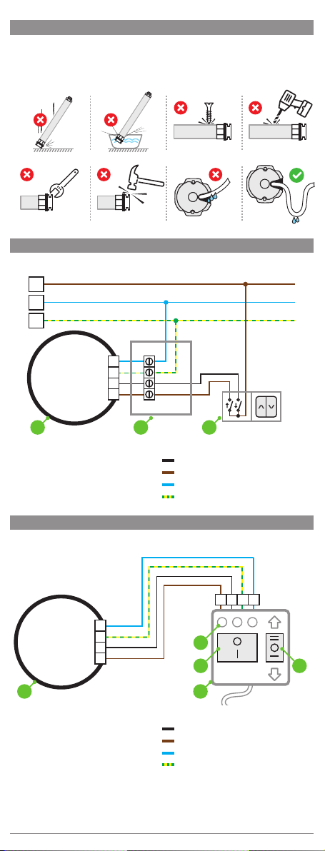
Tubular motor MOBILUS EP is equipped with the function of automatic configuration of the
end positions. It can be controlled by means of any wall switch - however, it is recommended to
use a support switch (using the switch without supporting it requires holding down the button
when lowering or lifting the armor).
The MOBILUS EP tubular motor is used in roller blinds drives.
The MOBILUS EP tubular motor has a protective function against current overload. This pheno-
menon may occur, e.g. when the blind is frozen or the armor is blocked in the roller shutter box
(requires the use of rigid hangers). The result of these events is the sudden stop of the motor
and the rapid increase in the current. Long-term overload may be dangerous for the motor, and
the solution used effectively protects against damage.
The current overload protection function in the MOBILUS EP motors is not identical to the OB-
STACLE DETECTION function possessed by the MOBILUS ERS SENSO motors.
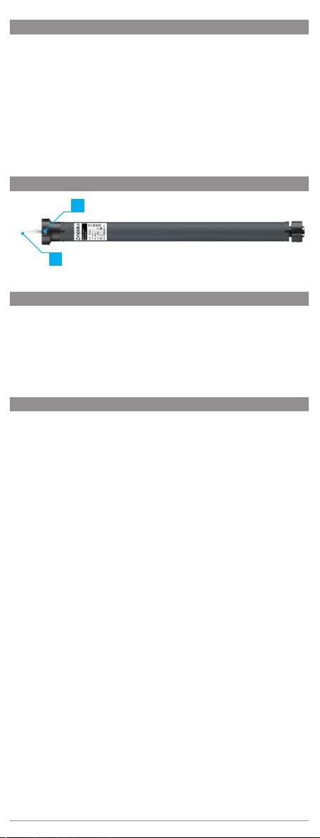
2. DESCRIPTION OF THE PRODUCT
2
1
1- Power cord. 2 - Settings button.
3. TECHNICAL PARAMETERS
Supply voltage: 230 V~ 50 Hz.
Limit switchers: Electronic
Protection rating: IP44
Insulation class: F
Continuous working time / break
time: 4 min / 90 min
Working temperature:
-20°C to +55°C
Nominal Power:
M35 EP 10/14 - 120 W
M35 EP 6/28 - 155 W
M35 EP 13/14 - 155 W
M45 EP 10/17 - 155 W
M45 EP 15/17- 175 W
M45 EP 25/17- 225 W
Torque:
M35 EP 10/14 - 10 Nm
M35 EP 6/28 - 6 Nm
M35 EP 13/14 - 13 Nm
M45 EP 10/17 - 10 Nm
M45 EP 15/17 - 15 Nm
M45 EP 25/17 - 25 Nm
4. IMPORTANT INFORMATION
The proper functioning of MOBILUS EP Motor depends on manufacturing the roller and its correct
installation. The shutter armor should move smoothly, without any obstacles along the slides. Pay
careful attention to:
• using slat hangers,
• using buffers in the endslat or stoppers in the slides,
• ensuring the lower point of the support – window sill, floor level or in the case of their absence in
the bottom part of the slides,
• the vertical fitting of the slides,
• smooth work of the shaft bearing,
•
deflection of the shaft (of the roll tube) caused by exceeding the width or weight of the shutter
armor,
• the high quality of shutter armor, especially of profile’s work in locks – armor’s beam cannot rub
against the box or its elements, e.g., thermal insulation (polystyrene) in the top-mounted roller
blinds.
Using of the MM 35 motors requires fulfilling the additional conditions. This is a consequence of using
the 40 mm octagonal roll tubes in which between roller-tube and the motor’s housing there is a small
space. There are some instructions that should be followed:
• Pipe’s seam cannot rub against motor’s housing,
• We recommend using pipes with the outer seam,
•
Motor’s position in the octagonal roll tube should enable the hanger’s installation in the largest
space between pipe and motor’s housing,
• The most safest is the hanger with the low catch.
We suggest using a switch without support (bistable).
The motor should be suitable for the blind’s weight.
The MOBILUS EP motor should only be powered from the power grid meeting the appropriate stan-
dards. It is forbidden to connect the MOBILUS EP motor to all types of generators / power generators.
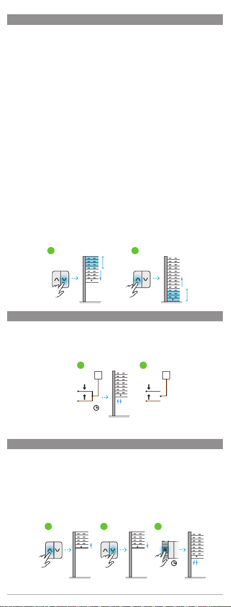
The MOBILUS EP motor enables setting the end limit switches in the AUTOMATIC MODE – using the
buffers is required. In this case, following issues have to be taken into consideration:
• The most profitable is using of the inside buffers installed in the lower endslat,
• In case of using the outer buffers that are installed in the lower endslat, they should be located on
the right side of the shutter armor. The point-intake designed for screwing should be located in the
distance not larger than 100 mm from the shutter armor’s edge.
2

5. SAFETY RULES
• Approaching to the moving roller blind is not allowed till it is completely closed.
The technical data of the tubular motor are given on its data plate.
The minimal pipe diameter in which the installation of the tubular motor is possible is 40 mm.
6. POWER SUPPLY SCHEME
L1
N
PE
N
PE
230V~ 50Hz
a b c
L1
L2
a) TUBULAR MOTOR
b) CONNECTION BOX
c) BISTABLE SWITCH
[WITH SUPPORT].
PHASE1
PHASE 2
NEUTRAL
PROTECTIVE
7. POWER SUPPLY SCHEME– PROGRAMMING WIRE
ab
PROGRAM
N
L1
L2
PE
PE1 N2
230V~ 50Hz
c
d e
a) TUBULAR MOTOR
b) PROGRAMMING WIRE
c) SIGNALING LEDS
d) PROGRAMMING BUTTON
e) DIRECTIONAL BUTTON
PHASE1
PHASE 2
NEUTRAL
PROTECTIVE
3

8. SETTING OF THE LIMIT SWITCHES –PROGRAMMING WIRE
ATTENTION!!! The PROGRAMMING WIRE is not attached to the motor.
It is sold as a separate product.
ATTENTION!!!Using spring roll hangers and buffers in the endslat or stoppers in the slides
is required.
Procedure for the motor with factory settings:
1. Connect the motor using PROGRAMMING WIRE according to the point 7 of the manual.
2. Use the DIRECTIONAL BUTTON to set any first limit switch - fig.8.1a.
3. Then press and hold the PROGRAMMING BUTTON until the first and then the second led
lights up red. The first switch limit has been memorized. - fig. 8.1b.
fig. 8.1
PROGRAM PROGRAM
ba
4. Using the DIRECIONAL BUTTON set the second switch limit - fig.8.2a.
5. Then press and hold the PROGRAMMING BUTTON until the first and then the second led
lights up red. The second switch limit has been memorized. - fig. 8.2b
fig. 8.2
PROGRAM PROGRAM
ba
6. Use DIRECTIONAL BUTTON to check if the switch limits have been programmed correctly.
If the switch limits are set correctly, disconnect the PROGRAMMING WIRE from the power supply
and then from the EP motor. Connect the EP motor according to the diagram - point 6 of the manual.
9. SETTING OF THE LIMIT SWITCHERS – AUTOMATIC MODE
ATTENTION!!!Using spring roll hangers and buffers in the endslat or stoppers in the slides
is required.
Procedure for the motor with fabric settings:
1. Press any key of the connector and hold it through the whole programming process.
2. The shutter armor will start to raise or lower until it reaches an obstacle – e.g. the shutter
box or a window sill – it will stop and bounce – fig.9.1a.
3. The MOBILUS EP motor will save the first (e.g. upper) limit switch position - fig.9.1b.
4. Then the MOBILUS EP motor will start to move the shutter armor in the opposite direction
-fig. 9.1c.
5. The shutter armor will start to raise or lower until it reaches an obstacle – e.g. shutter box
or a window sill – it will stop and bounce – fig. 9.1a.
6.
The MOBILUS EP motor will save the second limit switch- EP motor will make the up/
down motion – fig. 9.1 d.
fig. 9.1
db ca
7. Release the key.
ATTENTION!!! If during the programming the process of holding the key is stopped, limit swit-
ches will not be saved. Hold the key until the end of the programming.
10. SETTING OF THE LIMIT SWITCHERS – MANUAL MODE
ATTENTION!!! Using spring roll hangers and buffers in the endslat or stoppers in the slides
is required.
1.
Switch on and off the DIRECTION1 button twice, then switch on and off the DIRECTION2
button twice – fig. 10.1a.
2.
Press and hold the DIRECTION1 button , the motor will make visible , audible up/down
motion -fig. 10.1b –the shutter armor will start to raise or lower until it reaches an obstacle
– e.g. the shutter box or a window sill – it will stop and bounce.
4

CONTINUED 10. SETTING OF THE LIMIT SWITCHERS – MANUAL MODE
fig. 10.1
a b c d
2x 2x
3. The user can correct the position of a limit switch. In order to do that, stop the programming
process – release the DIRECTION 1 button, and then switch on and off the DIRECTION 2
button – fig. 10.2a. The motor works alternately – once up and once down.
fig. 10.2
ab
4. If the end position is set correctly, Press and hold the DIRECTION 1 button – the MOBILUS EP
motor will make visible, audible up/down micro motion and it will save the end position - fig.
10.2b, then it will start to move in the opposite direction until it reaches an obstacle – e.g.
the shutter box or a window sill – fig. 10.3a.
fig. 10.3
b
cd
a
a
5. If the user does not stop the process, the shutter armor will reach the second obstacle
– e.g. the shutter box or a window sill - it will stop and bounce. After a moment, the end
position will be saved - fig. 10.3b. Release the DIRECTION1 button.
6. If the user stops the process of setting the second limit switch (releases DIRECTION1
button) they will be able to adjust the second end position. In order to do that, switch on
and off the DIRECTION 2 button. The motor works alternately – once up and once down.
- fig 10.3c.
7. Press and hold the DIRECTION 1 button – the motor will save the adjusted second end
position – fig. 10.3d.
11. CHANGE OF THE SENSITIVITY TO OVERLOAD
The procedure of changing the sensitivity to overload of the EP motor:
1. Press and hold the DIRECTION 1 button through the whole process of changing the sensitivity to
overload – set the shutter armor to the end position – e.g. upper – fig. 11.1a.
2. Use the setting button in the motor head to change the sensitivity to overload:
1 flash – low sensitivity - in order to stop the work of the roller blind, a strong interference of
external factors, e.g. freezing of the blind, will be required – fig. 11.1b;
2 flashes – medium sensitivity - the motor ‘s tolerance for overloading is increased. The motor
will stop only when it feels significant resistance while the roller blind is working. – fig. 11.1c;
3 flashes – high sensitivity - after detecting the overloading, the motor will stop the roller blind
so that it will not be damaged – fig. 11.1d;
4 flashes – very high sensitivity - after detecting the slight overloading, the motor will stop the
roller blind so that it will not be damaged – fig. 11.1e;
3. Release the DIRECTION 1 button.
fig. 11.1
b c
d
a1x 2x
3x e4x
5
PROGRAMMING WITHOUT CORRECTION
PROGRAMMING WITH CORRECTION

12. THE FUNCTION OF PROTECTING THE SHUTTER ARMOR FROM DAMAGE
ATTENTION!!! Using spring roll hangers and buffers in the endslat or stoppers in the slides
is required.
MOBILUS EP motor has the function of damage protection. The internal counter counts the
number of disturbances that prevent further movement of the shutter armor. If there is a distur-
bance of the shutter armor operation 10 times in a row in a place other than the programmed
position of the limit switches, then the motor will save the place of the disturbance as the new
limit switch position during the 11th unsuccessful attempt.
ATTENTION!!! If at any time within the cycle the shutter armor overcomes the whole road from
one to the another limit switch, the counter will be reset and the new counting will start after
meeting the next disturbance.
Example: to lower the shutter armor - if during the work of the armor there is a disturbance
10 times in a row - (it does not reach the lower limit switch) during the 11th time motor will
save this place as the lower limit switch. Upper limit switch will be reset. If we start to raise the
shutter armor and we meet the disturbance – the box – the motor will „bounce” and save this
place as the upper limit switch.
Example: to raise the shutter armor - if during the work of the armor there is a disturbance
10 times in a row - (it does not reach the upper limit switch) during the 11th time motor will
save this place as the upper limit switch. Lower limit switch will be reset. If we start to lower
the shutter armor and we meet a disturbance – the box – the motor will „bounce” and save
this place as the lower limit switch.
The motor has an additional mechanism protecting from unnecessary change of the limit swit-
ches in the case of blinds freezing during winter time. It is based on the fact that any disturbance
occurrence that will stop the motor from working will not be counted in the log error if it occurs:
- While lowering the armor: on the section (measuring the beginning from the upper limit switch),
constituting 25% of the entire length of the road - fig. 12.1a,
- While raising the armor: on the section (measuring the beginning from the lower limit switch),
constituting 25% of the entire length of the road - fig. 12.1b.
fig. 12.1
a b
h: 25%
h: 25%
13. RESET OF THE MOTOR – RESTORE PRESETS
ATTENTION!!! Restoring of factory settings is deleting from the MOBILUS EP memory all learned
transmitters and all registered limit switches.
1. Connect the directional wires – black and brown with phase conductor at the same time
(fig. 13.1a) until the tubular makes a noticeable, audible single micro down / up motion
sequence. The motor has been restored to the factory settings.
fig. 13.1
ON OFFON OFF
2x
2-3 s.
L1 L1
a b
2. Disconnect the black, brown and phase wires (fig.13.1b) and connect them according to the
diagram (point 6). Leaving the wires connected will cause the MOBILU EP to reset cyclically.
14. RESET OF THE MOTOR–THE SETTINGS BUTTON ON THE MOTOR
ATTENTION!!! Restoring of factory settings is deleting from the MOBILUS EP memory all learned
transmitters and all registered limit switches.
It is possible to restore the factory settings using the SETTINGS BUTTON placed on the MOBILUS
EP motor head.
1. Start to raise or lower the shutter armor – fig. 14.1.a or fig. 14.1.b.
2.
While the motor is working press and hold the settings BUTTON placed in the EP motor
head. The motor will stop. Hold the button until the moment when the EP motor makes a
noticeable, audible single down / up motion sequence – fig. 14.1.c.
The motor has been restored to the factory settings.
fig. 14.1
a b c
6

ENVIRONMENTAL PROTECTION
This appliance is marked according to the European Directive on Waste Electrical and
Electronic Equipment (2002/96/EC) and further amendments. By ensuring this product
is disposed of correctly, you will help to prevent potential negative consequences for
the environment and human health, which could otherwise be caused by inappropriate
waste handling of this product. The symbol on the product, or the documents accom-
panying the product, indicates that this appliance may not be treated as household
waste. It shall be handed over to the applicable collection point for the waste electrical
and electronic equipment for recycling purpose. For more information about recycling
of this product, please contact your local authorities, your household waste disposal
service or the shop where you purchased the product.
15. RESET OF THE MOTOR – THE PROGRAMMING WIRE
ATTENTION!!! The PROGRAMMING WIRE is not attached to the motor.
It is sold as a separate product.
ATTENTION!!! Restoring of factory settings is deleting from the EP motor memory all learned
transmitters and all registered limit switches.
It is possible to restore the factory settings using the PROGRAMMING BUTTON placed in the
PROGRAMMING WIRE.
1.
Connect the motor using the PROGRAMMING WIRE according to the diagram – section
7 of the manual.
2.
Press and hold the PROGRAMMING BUTTON until the first and then the second led lights
up red – fig. 15.1a.
3. Hold the PROGRAMMING BUTTON until the second led goes out and the third led lights up
– fig. 15.1b. EP motor will make a down / up motion sequence – fig. 15.1.c.
The EP tubular motor has been restored to the factory settings.
fig. 10.1
PROGRAM PROGRAM
b ca
PROGRAM
4. Release the PROGRAMMING BUTTON.
7

8
SELECTION CHARTS
MOBILUS M35
φ 40 mm φ 50 mm
1,5 m 2,5 m 3,0 m 1,5 m 2,5 m 3,0 m
[ Nm ] [ rpm ] [ kg ] [ kg ] [ kg ] [ kg ] [ kg ] [ kg ]
6 28 10 8 6 8 6 3
10 14 19 17 14 17 15 12
13 14 28 26 23 26 24 21
MOBILUS M45
φ 60 mm φ 70 mm
1,5 m 2,5 m 3,0 m 1,5 m 2,5 m 3,0 m
[ Nm ] [ rpm ] [ kg ] [ kg ] [ kg ] [ kg ] [ kg ] [ kg ]
10 17 18 15 12 15 12 8
15 17 30 26 22 26 23 20
25 17 50 40 35 45 40 30
A
A
B
B
AINITIAL BEAM DIAMETER
BSHUTTER HEIGHT [ m ]
This manual suits for next models
6
Table of contents