charger is disconnected from the power supply.
•After normal usage, a minimum of 1 hour of
charging time is required to fully recharge battery
pack.
•The battery pack and the charger will become
slightly warm to the touch while charging. This is
normal and does not indicate a problem.
•Do not place the charger and battery pack in an
area of extreme heat or cold. They will work best
at normal room temperature.
NOTICE: The charger and battery pack should be
placed in a location where the temperature is
more than 32°F but less than 100°F.
•When batteries become fully charged, unplug the
charger from power supply and remove the
battery pack.
CHARGING A HOT BATTERY PACK
When using the tool continuously, the batteries in
the battery pack will become hot. You should let a
hot battery pack cool down for approximately 30
minutes before attempting to recharge. When the
battery pack becomes discharged and is hot, this will
cause the green LED to come on instead of the red
LED. After 30 minutes, reinsert the battery pack in
the charger. If the green LED continues to remain on,
return battery pack to your nearest Mokeneye
Authorized Service Center for checking or replacing.
NOTICE: This situation only occurs when continuous
use of the tool causes the batteries to become hot. It
does not occur under normal circumstances. Refer to
"CHARGING A COOL BATTERY PACK" for normal
recharging of batteries. If the charger does not
charge your battery pack under normal
circumstances, return both the battery pack and
charger to your nearest Mokeneye Authorized
Service Center for electrical check.
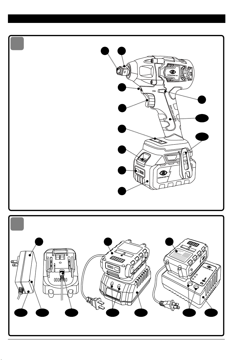
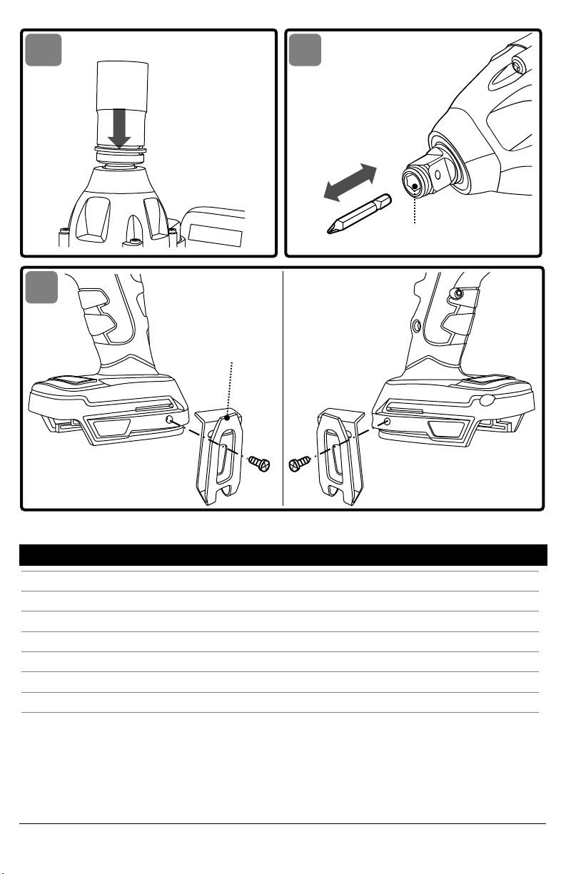
TO ATTACH/DETACH BATTERY PACK
See Fig. 3
Lock the variable-speed trigger switch "OFF" on the
tool by placing the direction-of-rotation
(forward/center-lock/reverse) selector in the center
position before attaching or detaching the battery
pack.
To attach the battery pack:
Align the raised rib on the battery pack with the
grooves in the tool, and then slide the battery pack
onto the tool.
To detach the battery pack:
Depress the battery-release button, located on the
front of the battery pack, to release the battery pack.
Pull the battery pack out and remove it from the tool.
NOTICE: When placing the battery pack onto the
tool, be sure that the raised rib on the battery pack
aligns with the groove inside the tool and that the
latches snap into place properly. Improper
attachment of the battery pack can cause damage
to internal components.
Battery tools are always in
operating condition. Therefore, the
direction-of-rotation (forward/center-lock/reverse)
selector should always be locked in the center
position when the tool is not in use or carrying it at
your side.
DIRECTION-OF-ROTATION SELECTOR
See Fig. 4
After tool use, lock the direction-
of-rotation selector in the "OFF"
position (center-lock) to help prevent accidental
starts and possible injury.
Your tool is equipped with a direction-of-rotation
selector located above the trigger switch. This
selector is designed for changing the direction of
rotation of the bit and for locking the trigger in the
"OFF" (center-lock) position.
1.Position the direction-of-rotation selector to the
far left of the tool for forward rotation.
2.Position the direction-of-rotation selector to the
far right of the tool for reverse rotation.
3.Setting the switch in "OFF" (center-lock) position
helps to reduce the possibility of accidental
starting when not in use.
NOTICE: To prevent gear damage, always allow the
IMPACT DRIVER WRENCH to come to a complete
stop before changing the direction of rotation.
NOTICE: The IMPACT DRIVER WRENCH will not run
unless the direction-of-rotation selector is engaged
fully to the left or right.
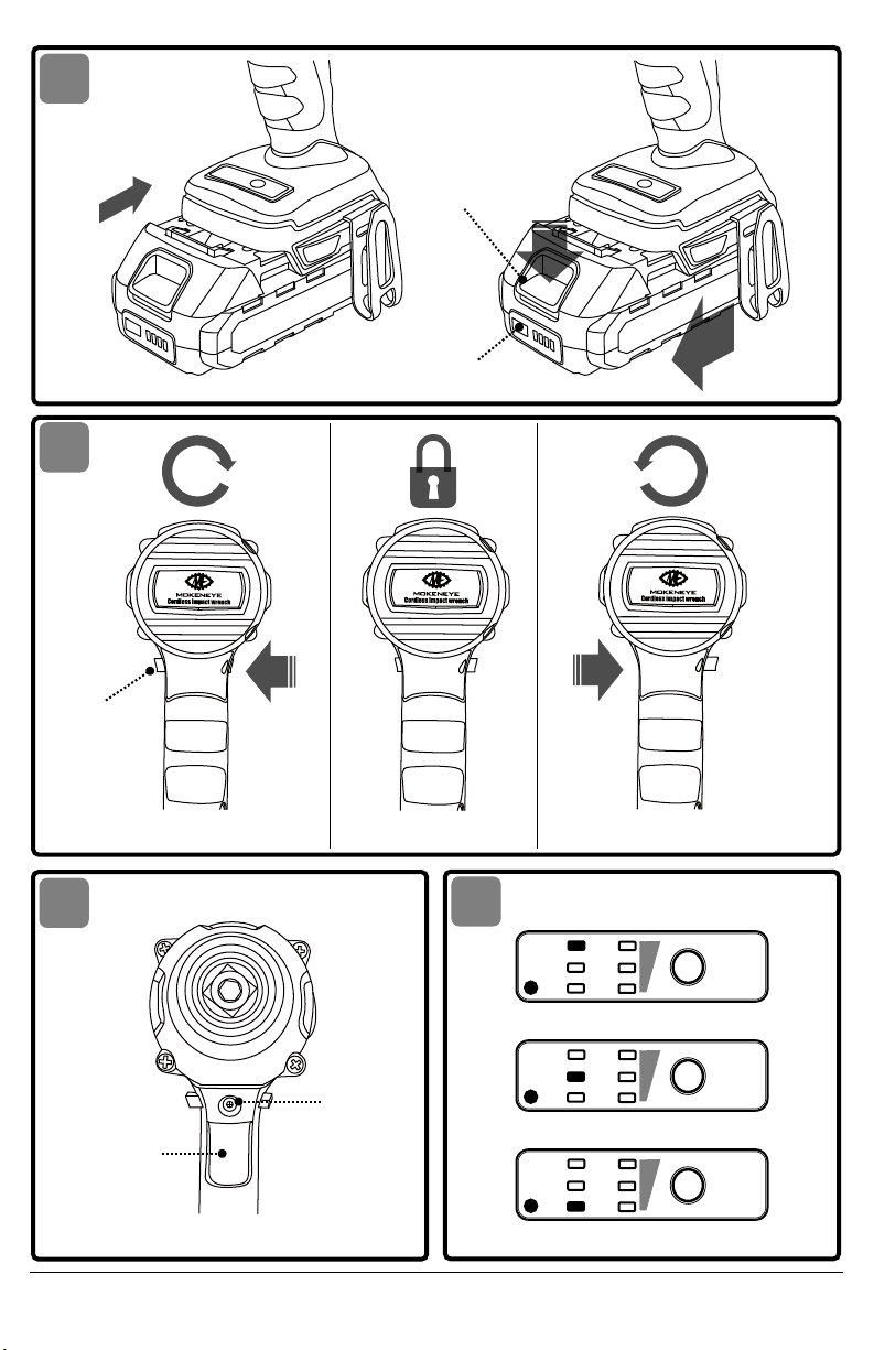
VARIABLE-SPEED TRIGGER SWITCH
See Fig. 5
Your tool is equipped with a variable-speed trigger
switch. The tool can be turned "ON" or "OFF" by
depressing or releasing the trigger.
The variable-speed trigger switch delivers high- er
speed with increased trigger pressure and lower
speed with decreased trigger pressure.
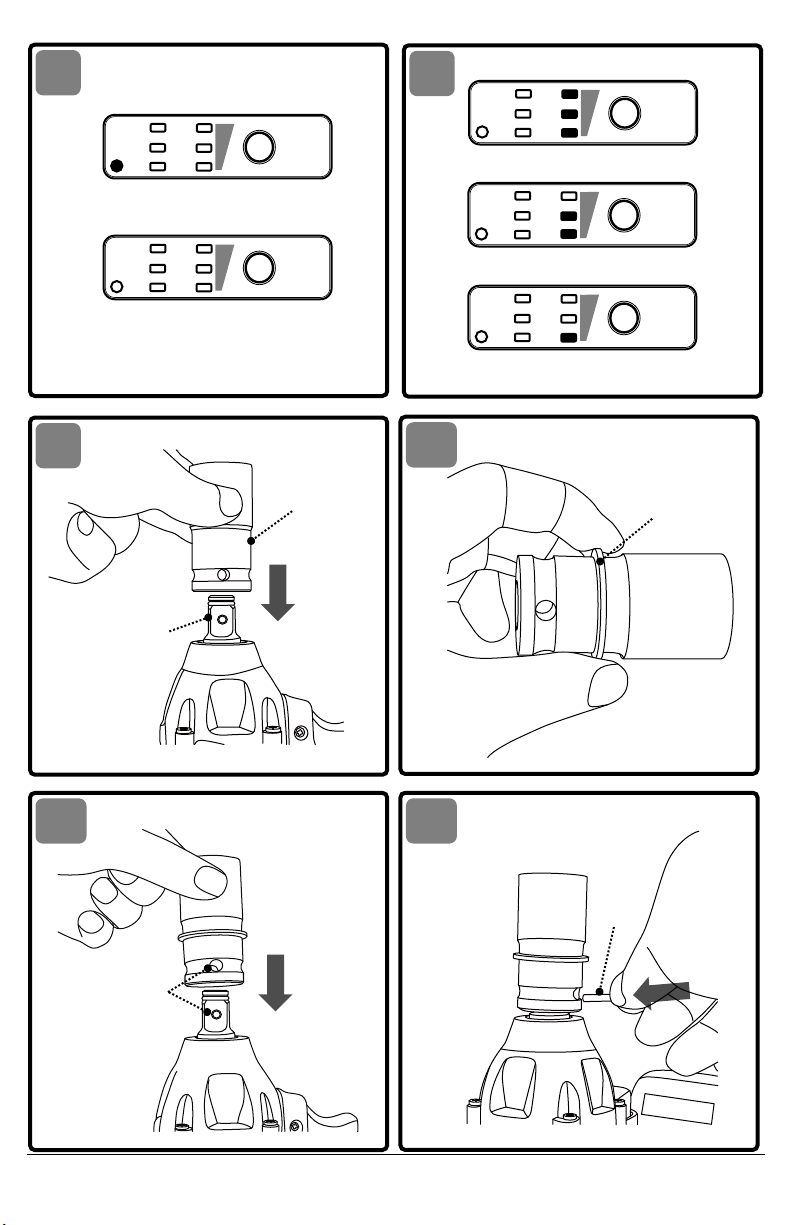
CHANGING THE IMPACT FORCE MODE
See Fig. 6,7
a.When the bit rotates clockwise (forward
direction), you can change the impact force
among 3 modes (low / mid / high) (Fig. 6). This
allows a tightening force suitable to the work.
Each time you press the red MODE button, the
mode program will be switched to low mode, mid
mode and high mode.
·Indicator light "L" shines green to indicate "low-
speed mode".
·Indicator light "M" shines green to indicate
"mid-speed mode".
·Indicator light "H" shine green to indicate "high-
speed mode".
b.When the bit rotates counterclockwise (reverse),
you can change the impact force among two
modes (Reverse Rotation Auto-stop Mode /
Standard Mode). (Fig. 7)
The innovative Reverse Rotation Auto-stop Mode
stops rotation and impact when fastener is
loosened adequately. This prevents the nut from