Moog Guitar User manual

Moog Guitar Service Manual
Introduction:
This document introduces the Moog Guitar from a service perspective. This instrument is the first commercially
available guitar to incorporate a true, closed-loop vibration-control system. The guitar’s behavioral module uses all
analog circuitry of a very complex, miniaturized and delicate nature.
In designing the Moog Guitar, we made every effort to meld the electronics and the instrument into a unified whole.
The electronics and the physical instrument must work together properly if the resulting instrument is to be good
enough to allow the guitarist to develop and display true virtuosity.
This service manual will help you restore a Moog Guitar to good playability.
---
To service the MG, you should be familiar with basic guitar and instrument service procedures such as truss rod
adjustment, intonation, dressing frets, etc. These guitar-related service procedures all apply to the MG, but this
manual will point out a few special points to watch out for.
The electronics in the MG should not be serviced in the field. Electronic service is by PCB replacement. At this time,
we are not releasing a guide for adjusting the PCB trims. It is relatively easy to replace the PCB, there are only a
few solder connections. However, you must carefully note the color codes and ordering of the wires and re-solder
each to its proper location.
You must also be prepared to cleanly de-solder and solder a few connections and possibly make some adjustments
using a Digital Volt Meter (DVM) and fine-tip probes.

Things to Watch Out For:
Electronics:
Please don’t attempt to make “experimental” trim adjustments except under direct on-the-phone guidance by a
Moog factory technician. (It’s pretty much impossible to get back to proper adjustment “by ear”.) There are no
opportunities to improve performance by misaligning these trims.
The components on the PCB are very delicate and easily damaged by ordinary accidental motions - lightly dragging
a pair of pliers across the PCB can do a whole lot of damage for example. Please take care not to leave any small
conductive “bits” in the guitar - sections of guitar string, bits of wire, etc. Anything like that could short out
components on the PCB.
The PCB is intended to “float” within the cavity. It should be pressed down into the cavity so the soft foam pads
around the sides of the cavity lightly secure it.
It is normal for the PCB and portions of the cavity cover to become noticeably warm during play. The internal
temperature is electronically limited to a safe value and the limit will probably never be reached under normal use.
Saddles:
More than the usual care is required to make intonation adjustments at the saddles. Each saddle is a delicate
piezo-electric sensor that can be damaged by excessive stress and strain forces. Please remove all tension from the
string and also release the center-saddle locking screw before adjusting saddle position and/or height. Do not
adjust saddles under string tension.
For good string tone, please make sure that both saddle height adjustment set screws are in solid contact with the
bridge saddle platform. Each set screw should firmly support its corner of the saddle. These saddles should never
be tilted.

Once a height or position has been adjusted, tighten the string almost fully before tightening the center-saddle
locking screw. This will allow the saddle to slip into its “natural” position. (You don’t want it doing that later during
a performance.) Lastly, re-tighten the center-saddle locking screw. Do not tighten this screw beyond the point
where it is clearly pressing down firmly on the saddle or you may bend or break the saddle body.
As a rule, to raise or lower the overall string action it is better and much easier to raise the entire bridge platform
rather than each individual saddle. (Remember to first check the neck for the right bias as this greatly affects action
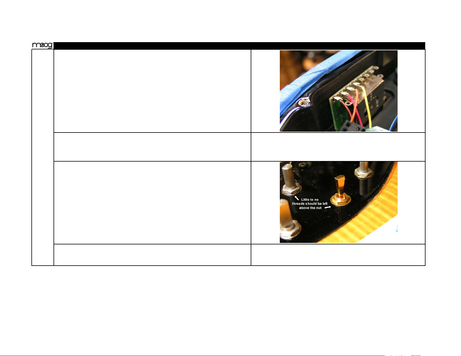
height.) In general, a saddle’s height adjustment set screws should not be over-extended, i.e., the saddle body
should sit fairly low to the bridge platform.
This advice applies to all installations of GraphTech Ghost saddles, not just the ones on the Moog Guitar.
Pickups:
If the pickup height has been tampered with it may be necessary to readjust the pickups.
Use care when adjusting the pickup height. The pickup screws are nylon; if you forcefully turn the screws too far
the screw threads will fail - don‘t go there! The screws are easy to turn with light force as long as they are within
the intended pickup adjustment range.
End to end pickup angle and height: The strength of control exercised by the pickups upon the strings varies
significantly with pickup height. The pickups should be adjusted so that the high-E ends are as close as possible
(without buzzing) to the high-E string when it is fretted at the top fret. The low-E string should be about 0.15”
above the pickup on the low-E side at the neck pickup. The bridge pickup can be a tiny bit closer to the string at
the low E.
In general, lowering the pickups will reduce control quality and strength.
Side to side adjustment: Looking down between the strings and pickup from the normal playing position, the
horizontal of the pickup should be parallel to the strings, i.e., there should be a constant distance between any one
string and the pickup surface as the string passes across the pickup.

Moo
g
Guitar Service Manual Example
Tape protection card under bridge to protect finish incase bridge is lowered against
guitar. This will remain until final inspection.
Hardware installation:
Pull (1) of each of the following: Pot assembly, Switch assembly, XLR assembly
(see Fig. B, C, and D for pre-assembly build instructions).
inspect each of these for quality solder connections (i.e. no cold solder joints, no
ex
p
osed wire to risk shortin
g)
.
inspect wiring for correct connections.
Add one rubber insulation pad on bottom of each pot housing.
Clip the locating tabs off each pot.
Depending on thickness of UI wood, place either a small lock washer or a large
lockwashe
r
between each of the 5
p
ots and the
g
uitar cavit
y
wood.
Place pots through correct panel hole so that washer allows just enough bushing
thread for one nut and washer on the outside of the guitar. If too many threads are
left, a thicker lock washer should have been used. This will be obvious once knobs
are installed and the nuts are visible underneath. Instead the knob should stop just
above the guitar surface, as seen in photo.
Continue installing all pots with lock washers, nuts, and washers. When all 5 are
installed, correct the pots' orientation and lightly tighten the nuts with a 10mm hex
driver. Their correct orientation should have all pot leads pointing in the direction
of the pick up cavities. Please be cautious not to over tighten. This will cause the
finish to se
p
arate from the wood.

Moo
g
Guitar Service Manual Example
Install the two blade switches with their circuit boards facing the outer rim of the
guitar. Please be sure the three position and five position switches are in the correct
location (see Fig C).
Install 4 machine screws for switches. Please be extra cautious to not over tighten
these screws. The switch will strip out and the guitar finish will get damaged. Make
sure all four screws are fully plated, without patches where black oxide has worn
off.
Install three position gold plated toggle with two small lock washers. This should
leave enough bushing to add one gold plated flat washer and one gold plated nut
one the outside of the guitar, without extra threads being visible.
Orient toggle so the white wire is closest to pick up cavities. Carefully tighten nut.
Please not over tighten, or mar the nut. This will not be covered with a knob and
needs to sta
y
cosmeticall
y
intact.

Moo
g
Guitar Service Manual Example
Insert XLR assembly so that release tab on XLR plug will be towards to ¼” jack.
Install 2 wood screws (add part number). If pilot holes have not been drilled, mark
the center location of the two XLR holes and drill small pilot holes about ½” deep,
then install screws.
Make sure 1/4" jack's nut is secure. Wire ¼” jack according to Fig D. Please be
careful of solder splatter around guitar finish.
Solder yellow and red ground wires to proper locations on breakout boards (see Fig
B, and C). Please be careful of solder splatter around guitar.

Moo
g
Guitar Service Manual Example
Install Pick u
p
s:
If not present, place foam cutout into each pickup cavity.
be sure that three holes in foam match the three screw holes in pick up cavity.
Place a pickup in each cavity with its wires passing through the holes joining to the
board cavity. The wires will have to be folded out of the way of the plastic pickup
standoffs.
Tighten six plastic screws until pickups reach their lowest position (this will protect
them from interferin
g
with, or bein
g
dama
g
ed b
y
, the strin
g
s
.
Pre
p
are cavit
y
for board installation:
Place 7 foam pieces in proper locations around board cavity. (see dots in photo for
locations). Place 5 strips of foam in proper locations of cavity bottom. (see
rectangles in photo for locations).

Moo
g
Guitar Service Manual Example
Dress wires from breakout boards so they don’t interfere with board installation. Be
especially cautious that wires aren't sandwiched and severed by board. This will
often occur around the switches and
p
ots.
Install Circuit board: *make sure to use proper static protection when
handlin
g
board.
Break circuit board out of frame using needle nose pliers to twist break away tabs
Connect four break away boards to main PCB, inside cavity, at correct locations
and correct direction (see photos).
Connect 8 solder points to main PCB (see Fig. D / photo).
Connect piezo saddles in correct order; shortest wire at top and longest wire at
bottom.

Moo
g
Guitar Service Manual Example
Connect 9V battery terminal. Due to alignment tabs on connector, this terminal
should only install in the correct orientation.
delicately press board into friction fit cavity. Start at piezo end of board and work
the rest of the board into the cavity around foam pieces. Shims may be necessary to
allow foam to hold the final portions of the board. Make sure board does not flex or
bend at any point.
add strain relief to piezo wires by installing zip tie through two holes in board and
around wires near connector.
group piezo wires together. Fold the group of wires into an “S” shape, then zip tie
bundle, including battery terminal wire for strain relief.

Moo
g
Guitar Service Manual Example
make sure wires won’t interfere with bridge movement or installation of cavity
cover.
Insulate brid
g
es and install saddles:
remove strings and bridge from guitar, if bridge has not been insulated. Be sure that
hex nuts are as loose as possible before removing springs. Take caution to protect
y
our e
y
es!
If not already installed, place six saddles on bridge in following order; #1 saddle, #2
saddle, #3 saddle, #3 saddle, #2 saddle, #1 saddle.
place piezo wires through oval cutout at the front of each saddle, slide each saddle
as far back on the bridge as is allowed, then lightly tighten the hex screws to hold
the saddles to the brid
g
e.
turn bridge over and place spacing fixture between wires and bridge block. Rubber
b
and the socket wrench across the wires to sandwich them in place on the bridge for
ta
p
in
g
.
Wrap capton tape around the bridge block and piezo wires two times to fix wires
firmly in place. Make sure tape is adhering to bridge between individual wires.
Remove wrench and spacer. Press wire slack against bridge. This gives the wires
room to move with the saddles, without being severed by the edge of the bridge.

Moo
g
Guitar Service Manual Example
Neatly lay all wires to the side of the bridge opposite the tremolo bar insert.
Securely tape the wires into this position.
If wires are all the same starting length, which they should be, the wire length after
taping allows each saddle to be distinguished after bridge installation.

Figure B

Figure C

Figure D

Moog Guitar Set Up Specs and Procedure:
Check Piezos:
Tune guitar. It is best for the bridge settling to tune strings in following order: G, high E, low E, B, A, retune G, D. Don’t be alarmed
if bridge adjusts itself during tuning.
Check piezo volumes to make sure the output levels are even and each piezo is working properly. If any piezos fail, the bridge will
have to be disassembled and the defective saddle replaced.
Adjust Bridge / Tremolo Assembly:
Adjust internal hex nuts so that the tension on the bridge is balanced between the force of the springs and the force exerted by the
strings (when the guitar is in tune). As the tension of one is changed, the tension of the other will have to be adjusted to compensate
for the balance of forces. When equilibrium is reached, the bridge should be sitting parallel to the surface of the guitar.
Now, use the tremolo arm to stretch out the springs in both directions. You will observe the bridge adjusting itself and no longer
sitting level on the guitar. Repeat the hex nut adjustments, and the spring stretching, until the bridge begins returning itself to the
parallel location after the whammy bar is used. This means the springs have been fully broken in.
Once springs have been broken in and bridge is sitting in proper location, place a small amount of “loc-tight” brand adhesive on each
hanger bolt, behind the hex nut, to prevent the nuts from self adjusting themselves over time.
*Note to tech- this bond will have to be broken to readjust bridge if set up is changed. Please be cautious that hanger bolts aren’t
turning with hex nuts, and that loc-tight is reapplied after setup is complete.
Setting Relief:
Tune guitar to pitch. Hold string at first and last fret. The string will now act as a straight line between the two points of these frets.
The distance between the string and the 12th fret should be just over that of the width of a couple sheets of paper.
If neck bow, or cupping, causes the distance to be incorrect in either direction, use the truss rod to adjust the curvature of the neck.
Minor turns (1/8 to 1/4 turn at a time) and continual checking should yield the perfect relief for your instrument.

Check by playing guitar – chromatic scales at 1st, 5th, and 12th frets. More relief is needed if buzzing occurs towards the nut but not
towards the bridge. Buzzing in the middle positions only will require less relief (more back bow). Buzzing everywhere requires higher
string action or lower pickups (see following).
Setting Action:
Overall saddle heights should mimic neck contour. When measuring string height at the 12th fret, the low E and A strings should
measure 4/64 from top of fret to bottom of string. Repeat this measurement on the D – high E strings. This measurement should also
read 4/64. This should yield a fairly buzz free guitar. If buzzing persists, increase saddle heights by increments of half 64ths until
buzzing is at a minimum. Saddle heights should not have to be raised more than at total of 1/64 to fix buzz.
Once guitar plays with no buzz, raise pick-ups to appropriate heights *(see footnote) and recheck for buzz. Once again, string heights
may have to be slightly increased to silence buzz.
Final action with pickups in place should not measure above 5/64th on low end and 4/64ths on high end. This is the worst case
scenario. Even at these heights, minor buzz may still be noticed.
Intonation:
The Moog Guitar’s intonation procedure should be the same as that of other guitars. The only variation may occur in the amount each
saddle needs to be adjusted in order to accurately intonate certain strings (often noticed on lower strings).
*Note to Tech- Please be cautious that piezo wires are not crimped or cut during saddle movements.
*Pickup heights when measured from bottom of string, fretted at 22nd fret:
Neck Pickup-
Low E High E
6/64ths 3/64ths
Bridge Pickup-
Low E High E
6/64ths 2/64ths
Other manuals for Guitar
2
Other Moog Guitar manuals
Popular Guitar manuals by other brands

Fender
Fender 0193460/3462 Switch & Control Function Guide

Squier
Squier Deluxe Hot Rails Strat Specifications

PRS Guitars
PRS Guitars SE Custom Semi-Hollow brochure

Gibson
Gibson 1962 Wilshire Reissue user guide

Steinberger
Steinberger Synapse EMGSYN-G-1 Specifications

Fender
Fender 72 Telecaster Deluxe owner's manual