Motec Race Grade M GPS BL V3 User manual

RaceGrade GPS
Part # M GPS BL V3
Available in 10 Hz or 20 Hz
Available with Multi-GNSS option
Availble with RaceGel option
USER MANUAL Version 3.0

Race Grade GPS
©Copyright –MoTeC USA –2019
RaceGrade is a registered trademarks of MoTeC USA Inc
MoTeC is a registered trademark of MoTeC Pty.
The information in this document is subject to change without notice.
While every effort is taken to ensure correctness, no responsibility will be taken for the consequences
of any inaccuracies or omissions in this manual.
27 September, 2019

RaceGrade
GPS Page 2
Contents
Introduction....................................................3
Warm Up Time.....................................................................4
Status LEDs .........................................................................4
RS-232 Serial Output...........................................................5
CAN Output..........................................................................5
20 Hz Update *Option ..........................................................6
Multi-GNSS *Option .............................................................6
RaceGel *Option ..................................................................6
Installation......................................................7
GPS Receiver ......................................................................7
Antenna................................................................................8
Loss of Signal.......................................................................9
Setup for MoTeC Loggers..................................................10
“i2” Analysis Math.......................................11
Appendix ......................................................12
GPS Engine Specifications ................................................12
Power Supply.....................................................................12
Operating Temperature......................................................12
Physical..............................................................................13
Connection.........................................................................13

RaceGrade
GPS Page 3
Introduction
Thank you for purchasing a
RaceGrade
v3 GPS receiver. This user’s
guide was written to help you understand how the
RaceGrade
v3
GPS (Global Positioning System) device works. Please read it
thoroughly. Installation is very important and understanding how GPS
works will help you get the most from this sensor.
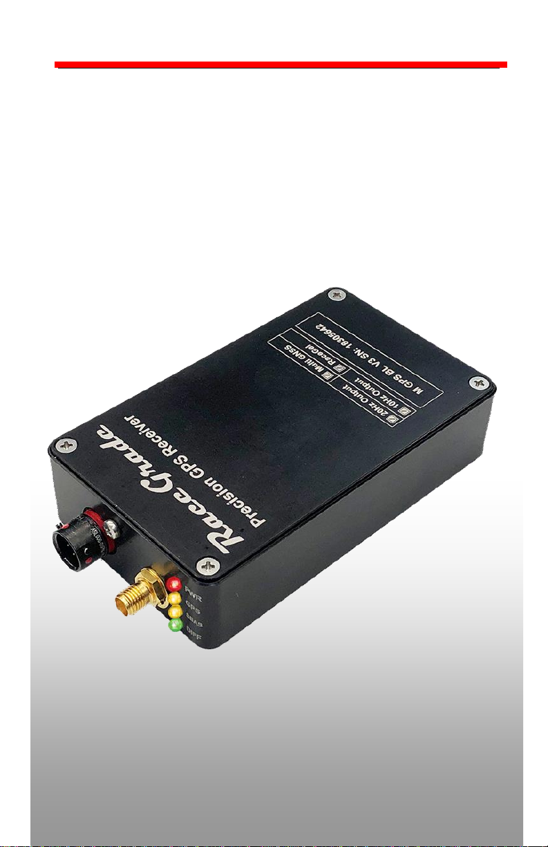
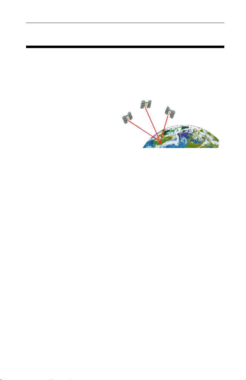
The RaceGrade v3 GPS
device uses a multiband GPS
specific antenna to track
satellites in orbit around Earth.
It takes a minimum of three
satellites to identify your position
on earth, and a fourth to
calculate accurate timing. Satellites are constantly moving, and a
satellite which the antenna sees at the start of an event might not be
visible minutes later. Satellites used in the GPS solution are dynamically
added or dropped based on signal quality. Ideally you should have 8 or
more satellites being tracked in order to obtain good accuracy. Anything
under 6 satellites is quite poor. With more satellites, there is more
information to correctly identify your position with less error. The key to
accuracy is your antenna having a clear, unobstructed line of sight to
the satellites in the sky.
The system uses a multi-frequency receiver to reference the
GPS, GLONASS, BeiDou, and Galileo constellations currently in
operation. Additionally, in certain parts of the world the GPS is able to
use up to three special geostationary satellites known as a Space
Based Augmentation System (SBAS). These satellites provide the
means to calculate DGPS (differential GPS) via reference station and
atmospheric modeling corrections.
The GPS system provides different levels of accuracy based on
where it is operated in the world. Without differential correction, you can
expect 8.2ft (2.5m) positional accuracy. When differential correction is
available, 95% of all data transmitted will be within 2.0ft (0.6m)
positional accuracy. Even more impressive is that up to 60% of all data
received with differential correction will have 1.0ft (0.3m) positional
accuracy. Satellite position and availability plays a large role in this
accuracy, so the more that are used in the position solution the better
chances you will have the higher accuracy in your position. This is why
the Multi-GNSS option is offered and strongly suggested for precision
oriented tasks.

RaceGrade
GPS Page 4
Warm Up Time
When the GPS receiver is first powered, it will start searching for
satellites to lock onto. This process takes time. It will take longer the
first time you power up at a new location from where you had previously
turned it off. Normal “cold” start up times, meaning being in a new area
from the previous location, can be anywhere from 2 to 10 minutes.
Subsequent “warm” start up times at the same location normally takes
30 seconds to 2 minutes. If you are outside of North American, expect
the very first time to take up to 20 minutes.
Internal Battery
There is an internal battery to store the recent location during power off.
This will aid in warm starts instead of cold starts, resulting in
dramatically less time to lock onto satellites. The internal battery is
rechargeable and after being off for several months may require
recharging to return warm start performance. The internal battery is
charged by system power and may take up to 24 hours to reach full
capacity.
Status LEDs
There are 4 LEDs on the front face of the unit labeled as follows:
LED
Color
Function
PWR
RED
Power is applied
GPS
YEL
GPS satellites are being tracked
SBAS
YEL
Correction satellites are being
tracked for differential position
solution
DIFF
GRN
Differential position calculation in
use which denotes high accuracy
position state (< 2.3ft / 0.7m)
There are only two required lights for operation, one is POWER and the
other GPS. The DIFF and DGPS lights indicate increased accuracy of
the data. With differential correction, you will get the most accurate
data. Therefore best operation is achieved with these lights on. The

RaceGrade
GPS Page 5
differential corrections are only available in regions of the world where
such correctional data is broadcast. The currently operational systems
referenced are WAAS (USA) and EGNOS (Europe). As future SBAS
systems come on line the receiver may need firmware updates to allow
for the correction.
RS-232 Serial Output
Standard NMEA-0183 message strings GPGGA and GPRMC are
sent out by default at a baud rate of 57,600. The baud rate and type of
messages can only be changed prior to sale or by sending the unit back
to MoTeC USA, Inc. on an RMA with the requested changes stated.
CAN Output
The RaceGrade GPS version 3 receive includes a CAN output.
The CAN bus speed operates at 1 mbit/s and on the base ID of 0x146.
The CAN output is based off the MoTeC GPS with STC (serial to CAN)
which mimics the NMEA0183 serial packet transmission. Simply select
the “GPS Async” template for MoTeC devices. A limited number of
alternate baud rate and message address can be requested if the
standard is not suitable for your application. They can only be changed
prior to sale or by sending the unit back to MoTeC USA, Inc. on an
RMA with the requested changes stated.

RaceGrade
GPS Page 6
20 Hz Update *Option
This option allows both the CAN and serial messages to update
at a true 20 Hz rate instead of the base 10Hz rate:
* Options must be specified at the time of ordering
Multi-GNSS *Option
This option allows the multiband GPS receiver to connect
additional GPS constellations currently including GLONASS (Russian),
BeiDou (Chinese), and Galileo (European)
you buy it afterwards, the unit must be sent to RaceGrade for
updating.
* Options must be specified at the time of ordering
RaceGel *Option
This option adds IP68 like environmental protection to the GPS
unit by flooding the enclosure with our proprietary potting. This option
requires at least two days lead time from the confirmation of an order.
The mass of the GPS receiver is significantly increased from 5.6oz /
158g to 8.0oz / 227g.
* Options must be specified at the time of ordering

RaceGrade
Notes 7
Installation
GPS Receiver
The enclosure is made from 6061 Aluminum alloy. It should be
mounted in a safe location, away from electrical noise, vibration and
temperature. Maximum operating temperature is 70°C or 158°F.
NOTE: To counter any possible vibration damage, please mount
the receiver with compliant hook and loop material. In high
vibration environments the RaceGel option is highly
recommended
Antenna
The RaceGrade GPS antenna included
with your unit is an active (powered)
high quality miniature dual band passive
device with a magnetic base. The antenna
is replaceable with our part number M
GPS BL ANT. Older versions of this
antenna are NOT dual band and would
significantly degrade the performance of
the Multi-GNSS feature. If you are
upgrading or mixing parts please be sure to
keep the new antenna paired with the v3
GPS. Non Multi-GNSS units will work with
either antenna, and the new dual frequency
antennas will work with older GPS units.
The location of the antenna is VERY important. It should be
mounted such that it can have a clear view of the sky out to 5 degrees
above the horizon. Poor mounting locations will have a negative impact
on the results from its calculated data.
Normally the best location would be on top of the vehicle. For
motorcycles, on top of the rear fairing works well. On a closed-wheel
race car the best choice is the roof. For best performance, do not place
the antenna under the front or rear window. For open-wheeled cars, on
top of the roll hoop, or just in front of the cockpit works best.

RaceGrade
Notes 8
Antenna
•GPS signals are easily blocked by electrical noise, especially in
the 1.5 to 1.6GHz range where GPS signals are transmitted.
Keep the antenna more than 6” from any other antennas such
as car-to-pit voice radios, telemetry and other GPS antennas.
•For cars with “live TV coverage cameras”, most of them send
their signal at the same frequency as GPS. Therefore you
must separate the GPS antenna and wire to the opposite side
of the car. Keep the TV antenna and wire as far away as
possible from the GPS antenna and wire.
•Keep the antenna outside any of any metal or carbon fiber
enclosed space, as these materials will block satellite signals.
Plastic, duct tape as well as fabric convertible tops are
generally ok.
•The antenna should be kept flat or parallel to the ground. If
mounted on a slope then the ability to receive signals will
decrease slightly. Keep this in mind when mounting on a
motorcycle as the bike leans from corner to corner.
•Try to keep the antenna mounted on the centerline of the
vehicle. As with normal wheel speeds, during cornering the
speed of the inner side of the chassis is less than the speed of
the outer side of the chassis.
•The antenna has a magnet base to hold itself onto a metal
surface. If you use double sided tape or hook & loop, when
removing please be careful not to remove the bottom silver
sticker from the antenna. This sticker has a metal film that help
reject false signals and shield it from noise.
•Any extra antenna wire can be zip tied in a back and forth
bundle. Do not coil the extra antenna wire length in a circle
or wrap it around anything. Simply run the extra antenna wire
back and forth.

RaceGrade
Notes 9
Loss of Signal
As mentioned earlier, the antenna must see as many satellites as
possible. The antenna should have a clear view of the sky, ideally a
clear line of sight to the sky down to 5 degrees above the horizon. If
part of the sky is blocked by a building, tree or bridge then the GPS unit
will loose track of those satellites being blocked. When this happens, a
reacquisition will take place which can take some length of time. Loss
of signal can occur when driving under bridges. The size of the bridge
and satellite location (time of day) has an impact on the acquisition of
satellites. You should always log your satellite count to be aware of
what the antenna saw while traveling around the race track.
GPS Quality
The channel “GPS Sats Used” is a value that represents the number of
satellites used in the calculations. A value of 8 to 10 is excellent. A
value of 6 or 7 is decent but may suffer some noise. Values below 6 will
have very poor accuracy.
For the RaceGrade GPS with the Multi-GNSS option, the number of
satellites should typically be in the neighborhood of 18 to 24 depending
on location and time of day. Prioity is always given to locking to the GPS
constellation first, and then foreign systems are added as their data is
confirmed to be reasonable with respect to the GPS data already
received.
The RaceGrade GPS carefully attempts to screen for multipath
(reflections of the same signal) which is why you will find it more difficult
to get lock inside of buildings or next to tall structures. Most other GPS
units accept multi-path signal and therefore lock more easily. For these
reasons the channel “GPS Sats Used” can not be analyzed to estimate
accuracy with any degree of precision in comparison between systems
other than RaceGrade receivers.

RaceGrade
Notes 10
Setup for Motec Data Loggers
For Motec Loggers, please select the template “GPS - Standard
RMC GGA” listed under the communications RS-232. Verify 57,600 for
the baud rate. You’ll be able to log the following channels of
information:
Recommended Logging Rates
Update Option: 10 Hz 20 Hz
•GPS Latitude 20 Hz 50 Hz
•GPS Longitude 20 Hz 50 Hz
•GPS Speed 20 Hz 50 Hz
•GPS Heading 20 Hz 50 Hz
•GPS Date 1 Hz 1 Hz
•GPS Time 10 Hz 10 Hz
•GPS Sats Used 10 Hz 10 Hz
•GPS Altitude 10 Hz 10 Hz
For the 10 Hz update rate, channels should be logged at 20 Hz even
though they only update at 10 Hz. This will help minimize the time delay
between when the data arrives to the logging device through the serial
stream and the moment the values are logged. For the 20 Hz option,
those channels which update at 20 Hz should be logged at 50 Hz. GPS
Date should only be logged at 1 Hz. See the table above.

RaceGrade
Notes 11
“i2” Analysis Math
GPS data will have an inherent time lag. The sequence of delays
are from receiving real-time satellite signals, processing them, sending
the data into the logger and the logger logging them. MoTeC’s “i2” has
a built-in “Corrected GPS” function found under the “Tools” pull down
menu. This function should only be used with data originating from a
MoTeC Data Logger or ECU.
Actual shift may vary. You can use either the Auto function or
manually adjust the time delay. The 10 Hz unit typically has a delay of
approximately 130 msec. The 20 Hz unit typically has a delay of
approximately 110 msec.

RaceGrade
Notes 12
Appendix
GPS Engine Specifications
•49-channel GPS engine capable of tracking GPS (USA), GLONASS
(Russian), BeiDou (Chinese), and Galileo (European) GPS
constellations when the Multi GNSS option is purchased
•Horizontal accuracy < 2.3 feet / 0.7 meter at 95% with DGPS
•Horizontal accuracy < 1.3 feet / 0.4 meter at 60% with DGPS
•Horizontal accuracy < 8.5 feet / 2.6 meter without DGPS
•Battery backed location storage for faster start up
•Option IP68 RaceGel potting available for extreme environments or
high vibration installations
•Update rate of 10 Hz or optional 20 Hz CAN and Serial
•Screw on SMA antenna connector.
Output Streams:
•RS-232 serial at 57600 baud rate formatted NMEA GGA and RMC
messages.
•CAN output for MoTeC devices (bus speed is 1 Mbit/s)
Power Supply
Operating Voltage: 6 to 18 Volts DC
Operating Current: 0.420 Amps at 12 Volts
Operating Temperature
Ambient Temperature Range: -22F to 158F / -30C to 70C
Housing Material: Anodized 6061 Aluminum

RaceGrade
Notes 13
Physical
Case Size: 3.95 x 2.35 x 0.9 inches (excluding connectors)
100 x 60 x 23 mm (excluding connectors)
Weight: 153 grams w/o antenna (227 grams w/IP68 option)
Connection
The mating connector is an ASL-606-05SN
•pin 1 –Ground, negative battery (do not use a 0v line)
•pin 2 –RS-232 Tx, serial data out
•pin 3 –12 volt supply, 6 to 18 volts allowed
•pin 4 –CAN Low
•pin 5 –CAN High
Table of contents
Other Motec GPS manuals