Motic MoticEasyScan Pro 6N User manual

If the equipment is used in a manner
not specified by the manufacturer,
the protection provided by the
equipment may be impaired.
Note
Complete reading of this manual
before opeartion is required.
MoticEasyScan Pro 6N
Instruction Manual
Changes or modifications not
expressly approved by the party
responsible for compliance could
void your authority to operate the
equipment.

1
TABLE OF CONTENTS
1. Device Safety Instructions 3
1.1 General Safety Tip 3
1.2 Safety Sign 3
1.3 Device Safety and EMC 4
1.4 Warranty Description 5
2. General Description 6
2.1 Product Application Range 6
2.1.1 Intend Use 6
2.2 System Overview 6
2.2.1 System Diagram 6
2.2.2 System Installation 7
2.2.3 System Connection Diagram 7
2.2.4 Port Description 8
2.2.4.1 Device Hosting Ports Description 8
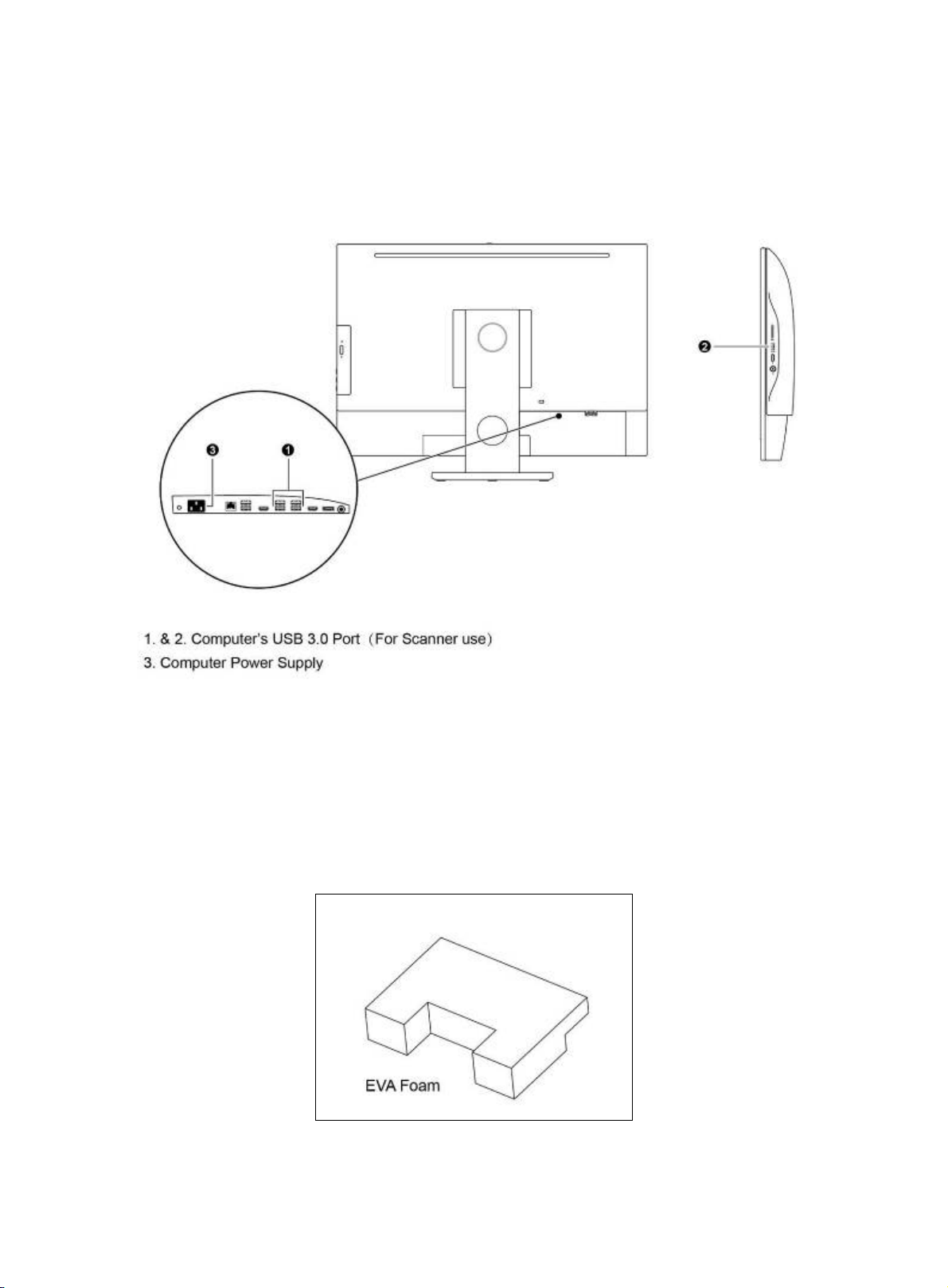
2.2.4.2 Computer Ports Description 9
2.2.5 System Connection Operation 9
2.3 Slide Tray 11
2.3.1 Slide Placement Procedure 12
2.3.1.1 Slide Loading Procedure 12
2.3.1.2 Slide unloading Procedure 13
2.3.2 Slide tray Loading Procedure 14
3. Software Installations and Instructions 15
3.1 Software Installation 15
3.2 Driver Installation 18
3.2.1 Driver Installation for Main camera 18
3.2.2 Driver Installation for Focusing Camera 20
3.2.3 Driver Installation for Macro camera 22
3.2.4 Driver Installation for MOXA USB Serial Port driver 24

2
3.3 User Interface 27
3.4 Slide Scanning 30
3.4.1 Slide scanning — operation interface 30
3.4.2 Slide Scanning — Advanced Mode Interface 30
3.5 Digital Slide Browsing 33
3.6 NFC Function 33
4. Operation Guidance 34
4.1 Cautions 34
4.2 Operation Instruction 34
5. Maintenance and Troubleshooting 35
5.1 Care and Maintenance 35
5.2 System Calibration 35
5.2.1 Calibration 35
5.2.1.1 Import Calibration File 35
5.2.1.2 Auto Calibration 37
5.2.1.3 Manual Calibration 38
5.3 Trouble Shooting 44
6. Appendix 45
6.1 Specifications 45
6.2 Electrical Specification 45
6.3 Working Environment 45
6.4 Storage Environment 46
6.5 Digital Camera System Specifications 46
6.6 Shifting of Instrument 46
6.7 Replacement of Parts & Accessories 47
6.7.1 Accessory List 47
6.8 Miscellaneous 47
6.9 Lens Cleaning 48
6.10 Cleaning of with Painting Components and Plastic Components 48
6.11 Idle time 48

3
1. DEVICE SAFETY INSTRUCTIONS
1.1 General Safety Tip
Before using the device, make sure to follow the instructions given in the Manual. For installation
instructions, please consult Chapter 2 and 3 of this Manual.
1.2 Safety Sign
The following signs are shown on the system. Every user must make sure to understand the definition of
the safety signs to always operate the device the most secure way.
Labels Meaning
l Main switch (ON).
○Main switch (OFF)
~AC
Caution: Pinching Hand
No Use
Warranty void if seal broken
Warning: Please do not enter during equipment
operation.
Representing uncertainty of the general danger.
Follow the descriptions on the back of signs or
follow manufacturer's instructions.
Biological hazard
Note: The device itself does not produce biohazard.
The biohazard is mainly derived from the
specimens/ slide used on the device.
In vitro diagnostic products

4
Please make sure the EVA foam is taken out before
starting any operation!! Detail please checks the
manual.
For damaged, missing or unreadable labels, please contact Motic Group Corporation for replacement
before continue operation.
1.3 Device Safety and EMC
● MoticEasyScan Digital Slide Scanning System is designed, manufactured and inspected in
accordance with the IEC 61010-1:2010/EN 61010-1:2010 and GB4793.1-2007 safety standards for
electrical measurement, control, adjustment and laboratory device.
● Electromagnetic is compatible to the standard of GB 18268.1-2010/IEC 61326-1-2005/IEC
61326-2-6:2005 and EN 55011.
● USB 3.0 port shall only be connected to certified computer according to IEC/ANSI/UL 60950-1 &
62368-1.
● Waste treatment disposal is implemented based on WEEE-Regulation 2002/96/EC.
Summary list:
Project Standard
Safety Regulations IEC 61010-1:2010/EN 61010-1:2010 & GB4793.1-2007
EMC GB 18268.1-2010/IEC 61326-1-2005/IEC 61326-2-6:2005 &
EN 55011
Device Scrap Disposal WEEE 2002/96/EC

5
1.4 Warranty Description
MoticEasyScan Digital Slide Scanning System and its components are only allowed to be operated
within techniques and processes described in this operation manual. Please noted: USB 3.0 port in
MoticEasyScan shall only be connected to certified computer according to IEC/ANSI/UL 60950-1 &
62368-1.
The manufacturer does not take any responsibility for damage caused by usage not complying with the
instruction in the Manual.
Please note the following warranty for MoticEasyScan Digital Slide Scanning System:
● Manufacturer warranty for material and product quality starts at the time of delivery.
● In case of malfunction, please inform the manufacturer immediately.
● If being notified of such a defect, the manufacture is obligated to repair the device or deliver an
intact replacement.
● Manufacturer does not assume warranty for those defects caused by natural wearing (especially the
wear & tear parts and consumables) or improper use.
● Operation of the equipment out of the functions described in this manual, negligence or replacing
equipment components will invalidate all warranty rights.

6
2. GENERAL DESCRIPTION
2.1 Product Application Range
MoticEasyScan Digital Slide Scanning System is a professional scanning device, with high-precision
motion control system and high-resolution digital imaging system which can scan 1 or 1 to 6 pieces of
glass slide in the tray at the time. Rapid high quality digital slide scanning can be achieved with Motic
digital slide scanning software Easyscanner. It is applicable for scanning, digital storage, transferring and
browsing of histopathology slide, cytology and biology slides etc.
2.1.1 Intend use
MoticEasyScan Pro 6N is applicable for image scanning, browsing, storage and transmission of
pathological slides.
2.2 System Overview
2.2.1 System Diagram
This product consists of device main unit, slide tray, computer and scanning software.
* If the equipment is used in manner not specified by the manufacturer, the protection provided by the
equipment may be impaired.
(Fig. 1)

7
2.2.2 System Installation
Before installation, please be familiar with following parts.
USB 3.0 cable Power Supply Cable
(Fig. 2)
2.2.3 System Connection Diagram
(Fig. 3)

8
2.2.4 Port Description
2.2.4.1 Device Hosting Ports Description
● MoticEasyScan Pro 6N
Connect the USB 3.0 of the MoticEasyScan Pro 6N to the USB 3.0 of your computer (the USB 3.0
port is usually blue or next to it, which Marked “SS”.)
(Fig. 4)

9
2.2.4.2 Computer Ports Description
USB port of host computer should be USB3.0 port, which is signed with SS or marked as blue color.
Computer Port Diagram
(Fig. 5)
2.2.5 System Connection Operation
*** Please make sure the EVA foam (Fig. 6), which is inside the MoticEasyScan Pro 6N is taken out
before starting any operation
(Fig. 6)

10
● Firstly, manually disassemble the locking screw on the both sides of front U shape panel. And
remove the U shape panel. (Fig. 7a)
● Then slide the front panel out in horizontal direction from the device. (Fig. 7b)
● Cut the nylon cable tie
● Remove the EVA foam carefully. (Fig. 7b)
● Slot the front panel and the U shape panel back into the MoticEasyScan Pro 6N and lock the locking
screw.
(Fig. 7a)
(Fig. 7b)

11
● MoticEasyScan Pro 6N Connection
a. Please make sure that all power is switch off before connecting.
b. Take reference of system connection diagram (Fig. 4), follow the steps below for connection.
■ Plug one end of USB3.0 line to USB port of scanner and connect the other end to USB3.0 port
of computer.
■ Make sure system power is switch off, plug the power cord to the power socket of the scanner
and connect the other end to a safety rated Power outlet.
2.3 Slide Tray
(Fig. 8a)
2.3.1 Slide Placement Procedure:
2.3.1.1 Slide Loading Procedure:
a. Hold the edge of the sides with the thumb and index finger, follow the direction of Fig.9a, load the
slide under the clip Fig. 8b-② with 15 degree angle, then push it to the end .
b. Push the slide with barcode end downward to the direction of clip Fig. 8b-① and in the meantime
the other hand move beneath clip of Fig. 8b-① to assist the slide goes into the clip.
c. Make sure the slide is pushed against the left side of Fig. 8b-③ as shown in Fig. 9c

12
Note:
Ensure the backside of clip Fig. 8b-① and Fig. 8b-② are pressed on the top of the slide.
Try not to touch the cover glass on the slide during the whole process.
(Fig. 9a) (Fig. 9b)
(Fig. 9c)

13
2.3.1.2 Slide unloading Procedure:
a. Hold the slide with index finger and thumb, unload the slide by pushing the slide towards the
direction of clip Fig.8b-① until the other end of the slide can be lifted (Fig. 10a)
b. Lift the slide upward to move out of the slide position (Fig. 10b)
Note: Try not to touch the cover glass on the slide during the whole process.
(Fig. 10a) (Fig. 10b)

14
2.3.2 Slide tray Loading Procedure:
a. Open the right flip cover, load the slide tray with the direction shown in the figure, and make sure
the top surface of slide-tray fits below marked line (Fig. 11a).
b. After inserting the slide-tray, ensure the triangle arrow of positioning slot “GO” points to the dot
(Fig. 11b).
(Fig. 11a)
(Fig. 11b)

15
3. SOFTWARE INSTALLATIONS AND INSTRUCTIONS
3.1 Software Installation
a. Double-click Setup.exe file in the installation program;
b. Select installation language and click on the “Next” button;
c. Then click “Next” button;

16
d. Select installation path and click “Next” button;
e. Select the database installation path and click the “next” button;
f. Click “Install” button to proceed installation and display installation process;

17
g. When installation is completed, click “Finish” button to complete software installation

18
3.2 Driver Installation
3.2.1 Driver Installation for Main camera
a. Find the camera in the “Device manager”, then click “Update Driver Software”.
b. Click “Browse my computer for driver software”.
c. Click “Browse”, select Drivers\PointGrey in the folder, and click “Next” button.

19
d. The files are being copied to your computer.
e. When the installation is completed, close the window in the following figure to complete the driver
installation. To ensure the proper work of your device, please restart your computer.
Table of contents
Other Motic Scanner manuals