Mountain Mods BOB SLAY User manual

BOB SLAY
(assembly instructions)
Items included:
7 x Acrylic cutouts labeled A-G
1 x Acrylic IO Panel
1 x Acrylic locking plate of PCI cards
2 x Acrylic 5 25 spacers
2 x momentary switches (power/reset)
2 x blue tailed LED w/chrome bezels
1 x stainless steel handle w/2 mounting screws
6 x PCI cover plates
1 x bag of motherboard mounting hardware (10 standoffs, 10 screws)
1 x bag of left sided acrylic blocks (10 pcs – labeled “L”)
1 x bag of right sided acrylic blocks (10 pcs – labeled “R”)
1 x bag of long 3mm screws (60 pcs)
1 x bag of long 6/32 screws (16 pcs)
1 x bag of long fan screws (8 pcs)
Assembly:
Find the acrylic cutout labeled “A” on one side. This is the bottom of the case. On one side protective
film will need to be removed from the acrylic while the other side will already have the film removed and
4 lon sled like feet adhered to the plate.

Find the acrylic piece labeled “B”. This is the front of the case. On one side protective film will need to
be removed. The other side will already have the film removed and the name “Bob Slay” as well as the
Mountain Mods lo o etched onto it.
After removin the film from parts A and B take a left sided acrylic block and fasten it to part A.
Each block has 3 inserts for mountin hardware. Take Part B and ali n it to the bottom front ed e of
Part A to see how you will need to mount the block. Do the same with the ri ht side of the bottom of the
case with a ri ht sided acrylic block. Below is a picture of parts A and B attached in this manner.

Next take the acrylic panel labeled “C” and remove the film from both sides. Part C is the backside of
the case. Lookin at the back of the case take a ri ht sided acrylic block and mount to the ri ht side of
the case and a left sided acrylic block to the left side of the case.
Now still lookin at the backside take another left sided acrylic block and fasten it to the left side of the
back panel on the midsection. There are 4 blocks on the midsection of the case that act as platform for
the motherboard tray to sit upon. The midsection blocks will need to sit 90 de rees in difference from
the bottom level blocks as the motherboard tray mounts to the inserts on them. Mount the ri ht backside
acrylic block and then do the same thin on the front side so that all 4 blocks are fastened to the midsec-
tion.

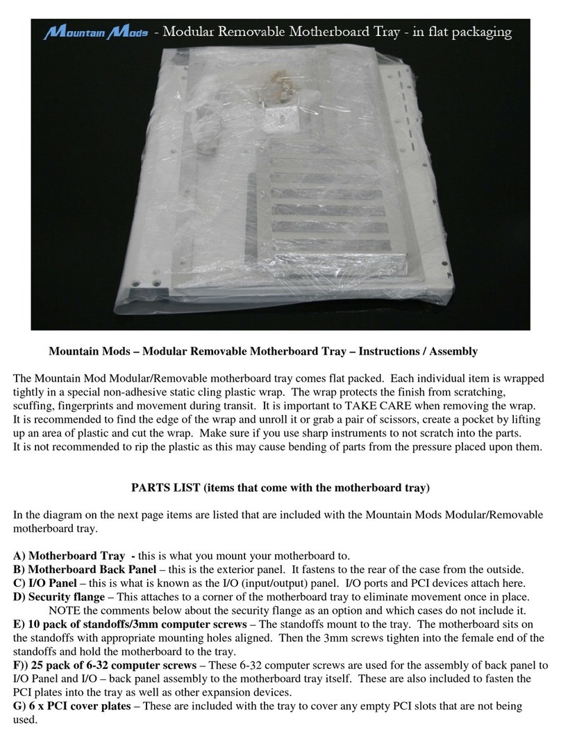
Now find the panel marked “E”. This is the motherboard tray. Remove the protective film from both
sides of the tray. Take the standoffs out of the motherboard hardware ba and mount them into the
motherboard tray. Ten holes have been tapped for the standoffs. Some motherboards will not use all
standoff points. Consult your motherboard manual or examine it before placin all standoffs in the
holes. When applyin the standoffs do so at first by hand. Then ti hten with a wrench or pliers if
needed. Do not over ti hten. Over ti htenin may result in strippin of the threads on the acrylic.
Next place the tray into the midsection of the case so that the PCI plate cutouts are on the ri ht (front
side an le) of the case. Insert 3mm screws in each corner and ti hten the tray. Ali n the ed es of the
tray to the outside of the acrylic blocks as best as possible. Also apply pressure to the front and back
panels while ti htenin so that little or no aps are between the tray and the panels.
Now find the 2 x 5.25 bay spaces and join your 2 x 5.25 devices to ether. You will need to keep a
device that has bottom mountin holes on the bottom. Most CDR or DVD devices will have these.
Join the devices as shown below.

Place the case on its side (ri ht side so that you can see the bottom of the case). Now Slide the joined
5.25 devices inside the case from the open side (Do not attempt to slide into the front hole for these
devices). Move the front bezels of the devices forward until they are flush with the acrylic on the front of
the case. Take note of where the mountin holes are on the bottom 5.25 device. Line these up with the
holes on the bottom of the case. Insert lon 3mm screws and ti hten the devices in place.
Now flip the case back upri ht and slide your Power Supply (PSU) into the left side openin of the case.
Move the PSU so that the mountin holes ali n up to the mountin holes on the back panel. Mountain
Mods su ests usin a power supply that includes an intake fan to help remove heat from the hard drive
(s). Take 4 lon 6/32 screws and ti hten the PSU into place.
Next take your hard drive (HD) and mount it to the bottom of the case usin the bottom mountin holes
on it. If you are usin multiple hard drives (up to 3) you will need to purchase the optional acrylic HD
expansion spacers. The function exactly as the 5.25 spaces above. Use 4 lon 6/32 screws to mount
the HD(s) into place. You should now have somethin that looks like this on the bottom side.

Take the 2 x chrome led bezels with tailed blue LED's and the 2 x nickel plated momentary switches and
install them into the front panel. Due to the thickness variation on the acrylic some panels may be too
thick to make use of the nut on the chrome bezels. The holes should be ti ht enou h to secure the LED
bezel in place. If they seem loose you can use a bit of scotch tape and wrap around the bezel in order
to make the fit more snu . Press the bezels into the front panel fully. The nickel plated switches extend
well into the chassis. Then simply ti hten the nuts onto the backside of the panel.
Now find panel “D” and the IO panel. Be very careful with both pieces as they have some areas of small
material that can easily break. Remove the protective film with care.
After removin film turn the IO panel so that the smaller portion is to the left and the PCI openin s are to
the ri ht. Take panel D and Ali n on top of the IO panel. Line up the 6 mountin holes from the panel
with the IO panel. Insert 6/32 screws into panel D. Ti hten them makin sure to enter the correlatin
hole on the IO panel. Turn the case so that you are lookin at the PSU side of it. Insert a ri ht acrylic
block on the bottom middle of the case. Then a ri ht block on the top ri ht and a left side acrylic block
on the back left. You can place Panel D so the IO panel rests directly on the Motherboard acrylic panel
(panel E). Doin this will indicate which way to rotate the blocks in order to fasten correctly. Once you
have the blocks fastened to the mid-section of the bottom panel, ri ht front, and left back then fasten
Panel D with the lon 3mm screws into the acrylic blocks. Then insert one more block on panel D on the
top mid-section.

Now is a ood time to install your Motherboard. First take the IO cover panel that comes with your
motherboard and insert it into the panel openin . Be very careful. If the panel seems too snu try to
take the ed es and press them in a bit before forcin into the acrylic panel as this expansion may cause
the acrylic IO panel to break. Now place your motherboard onto the standoffs of the tray (you should
have already installed these). It is probably best to install your CPU heat sink and memory prior to
placin it into the case, but not absolutely necessary. Take the short 3mm screws from the motherboard
mountin hardware ba and ti hten them into the brass standoffs securin your motherboard in place.
Next you can start routin your cables and insertin PCI cards and blank cover plates. You will probably
need to tweak the cover plates a bit by hand prior to placin them in their slot. They are of thinner
material than most PCI cards. Given that the PCI cards and cover plates to do not screw in individually it
becomes more important to try and compensate for this material difference as a sin le lockin bar will be
holdin the cards/covers into place.
PCI Cover plates above left (ri ht one bent a bit for thickness compensation). PCI acrylic lockin bar
pictured above ri ht. Case at current state below.

Remove the protective film from the acrylic lockin bar prior to installation. Hold cards into place while
screwin down the ri ht side of the lockin bar into place. Then put pressure on the left side of the
lockin bar to ali n mountin holes and fasten the remainin screw. This should secure your cards and
cover plates. If any are loose try bendin the metal piece that you would normally fasten with a screw
sli htly up as pictured above.
Now install your intake and exhaust fans usin the 8 lon fan screws included with the case (standard
fan screws will not be lon enou h). The front and back of the case have unobstructed blow hole
openin s for maximum airflow. These are desi ned for 120mm fans of no more than 25mm thickness
(standard 120mm fan). Note some CPU coolers may be too lar e and interfere with the intake fan on
the case. You can however mount the intake fan on the exterior of the case if needed. If your CPU heat
sink extend past the front of your motherboard you will have need to externally mount the intake fan.
This would can be done easier prior to mountin the motherboard into place. The maximum hei ht of
your CPU heat sink/fan can not exceed 4.5 inches without interferin with the top of the case. Placin
an aluminum mesh fan filter on the intake fan will help keepin the interior of the acrylic clean.
After securin all connections from the lower portion of the case to the top it is time to fasten the left wall
(panel “F”) to the case. First remove the protective film from the panel. Then fasten a ri ht side acrylic
block to the bottom mid-section of the case. Then fasten a left side block to the left front and a ri ht side
block to the ri ht back of the case. A ain you can use the panel to help determine the hole positionin
on the blocks. Then ali n and fasten the panel to the blocks.
Now rab the last panel, panel “G” and remove the protective film from it. Locate your stainless steel
pull rod/handle and 2 8/32 screws. Fasten the rod to the mountin holes in the center of the panel.

Now fasten the remainin acrylic blocks to the case. On the front you will have fasten 2 blocks. A left
side block on the left side and a ri ht side block on the ri ht side. Use the top panel to determine
placement of the blocks. Turn the case around to look at the back side and do just as you did in the
front. The 2 remainin blocks fasten to the top side walls. The left side block fastens to the left side and
vice versa. Then place the lid into place and fasten all 10 screws into the acrylic blocks.
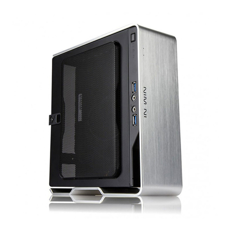
CONGRATULATIONS!!! you should now have somethin that looks like this.
Usin the Bob Slay is much easier once it is assembled. To add new cards or manipulate the
motherboard portion just remove the top shell. If you need to throw in a cable or replace a drive just
remove the left side panel. If you need full access to everythin try removin both the top and left side
panel.
Other Mountain Mods Enclosure manuals
