Moving Colors Yellow Line User manual

www.movingcolors.eu
Yellow Line 4K/IP Extender
1
Moving Colors Yellow Line
4K over IP
Transmitter & Receiver
Operating Manual

www.movingcolors.eu
Yellow Line 4K/IP Extender
2
Contents
1. INTRODUCTION ................................................................................3
2. FEATURES..........................................................................................3
3. PACKAGE CONTENTS.........................................................................4
4. HARDWARE DESCRIPTION.................................................................4
5. BUTTON DESCRIPTION......................................................................7
6. INSTALLATION.................................................................................11
7. IP CONFIGURATION.........................................................................15
8. WEB USER INTERFACE CONFIGURATION .........................................19
9. BROADCAST CONFIGURATION SETTING ..........................................40
10. SPECIFICATION................................................................................45

www.movingcolors.eu
Yellow Line 4K/IP Extender
3
1. INTRODUCTION
The 4K HDMI & USB over IP Extender is a solution for audio, video and USB
signal extension via LocalArea Network (LAN). It can be used as audio,
video and KVM extender over IP and applied to point to point, point to
multi-point, multi-point to multi-point and video wall broadcast system
controlled by USB, RS232, IR and configured the 4K HDMI & USB over IP
Extender by WEB GUI and PC GUI. An easy installation system built up with
Gigabit Ethernet switch which has IGMP function and CATx cable for
extension or broadcast.
2. FEATURES
•4k UHD HDMI over IP/Fiber Extension
•USB2.0 over IP extension
•Transmission distance 120m over single Cat5e/6 cable
•Fiber optical up to 60KM (Single Mode)
•Input 4k@60hz YUV 420 (Max), output 4k@30hz (Max)
•HDCP 2.2 / HDCP1.4 compliant
•Bi-Directional Wide Band IR (38KHZ-56KHZ) Pass through
•RS232 pass through and control, Telnet command
•IR remote/Button to control the Group ID,
•LED to show the Group ID
•Dolby True HD, DTS-HD Master Audio
•Input audio: SPDIF 5.1 and L/R Stereo analog Line mixed
•Output audio: SPDIF 5.1 and L/R Stereo Analog audio extraction
•Unicast, Multicast, Video Wall system (Max 8x16), Output video
Rotation
•10-Gigabit IGMP Ethernet Switch can be cascaded for many layers
•802.3af compliant POE, no need power supply when connecting
with POE IGMP Switch
www.movingcolors.eu
Yellow Line 4K/IP Extender
4
3. PACKAGE CONTENTS
•Main Unit. HDMI Extender (Transmitter & Receiver)
•2x Power adapter DC 5V
•2x IR TX cables, 4x IR RX cables
•2x Phoenix plugs for RS232 cable termination
•8x screws
•4x detachable mounting ears
•2x Remote controller
4. HARDWARE DESCRIPTION
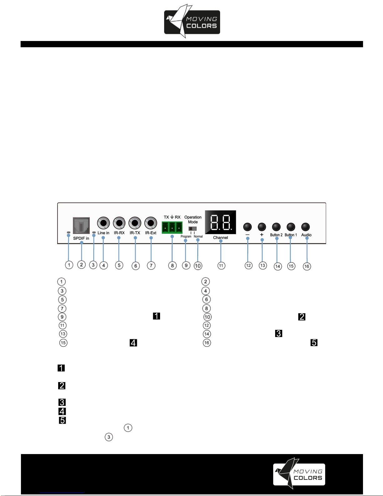
4.1 Transmitter
Front panel
Indicator of SPDIF Audio SPDIF Audio in
Indicator of analog Audio Analog Audio line in
IR-RX IR-TX
IR for group control RS232 by pass
Program: RS232 control Normal: RS232 by pass
LED for group ID Group down picking
Group up picking Functional button
Functional button SPDIF/Analog Audio switch
Note:
Under “program”status, RS232 control the units, and Remote is in
available to change group ID
Under “normal”status, RS232 is bypass, and the Remote is available to
change group ID
Functional button refer to 5.3 description chart
Functional button refer to 5.3 description chart
Audio is input from HDMI by default, first press to switch to SPDIF audio
input and indicator light up, second press to switch to analog Audio input
and indicator light up
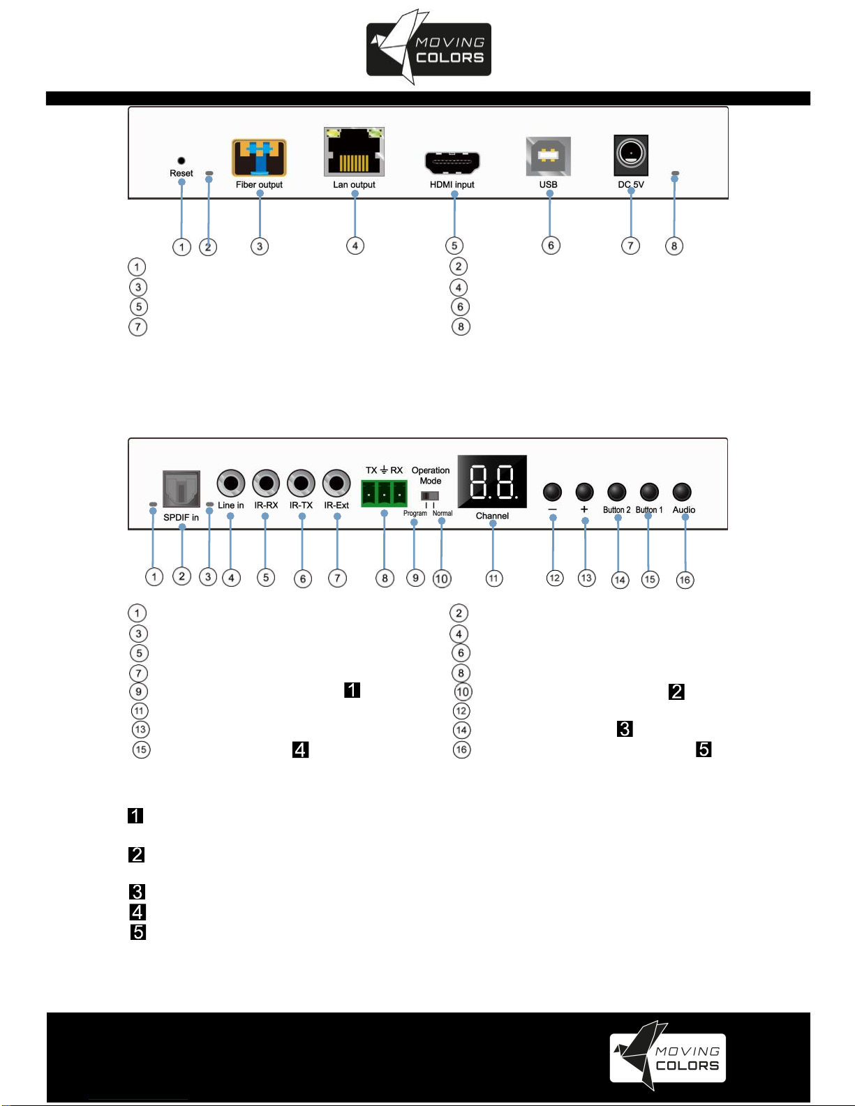
Rear panel
www.movingcolors.eu
Yellow Line 4K/IP Extender
5
Reset Indicator of Fiber output
SFP fiber output CAT5e/6 output
HDMI input USB type B input
DC 5V input Indicator of Power input
4.2 Receiver
Front panel
Indicator of SPDIF audio SPDIF Audio output
Indicator of Analog audio Analog Audio output
IR-RX IR-TX
IR for group control RS232 bypass
Program: RS232 control Normal: RS232 by pass
LED display group ID Group down picking
Group up picking Functional button
Functional button SPDIF/Analog Audio switch
Note:
Under “program”status, RS232 control the units, and Remote is in
available to change group ID
Under “normal”status, RS232 is bypass, and the Remote is available to
change group ID
Functional button refer to 5.3 description chart
Functional button refer to 5.3 description chart
Audio is always output from HDMI, first press to switch to SPDIF audio
input and indicator ①light up, second press to switch to analog Audio input
and indicator ③light up

www.movingcolors.eu
Yellow Line 4K/IP Extender
6
Rear panel
Reset Indicator of Fiber output
SFP fiber input CAT5e/6 input
HDMI output USB type A output
DC 5V input Indicator of Power input

www.movingcolors.eu
Yellow Line 4K/IP Extender
7
5. BUTTON DESCRIPTION
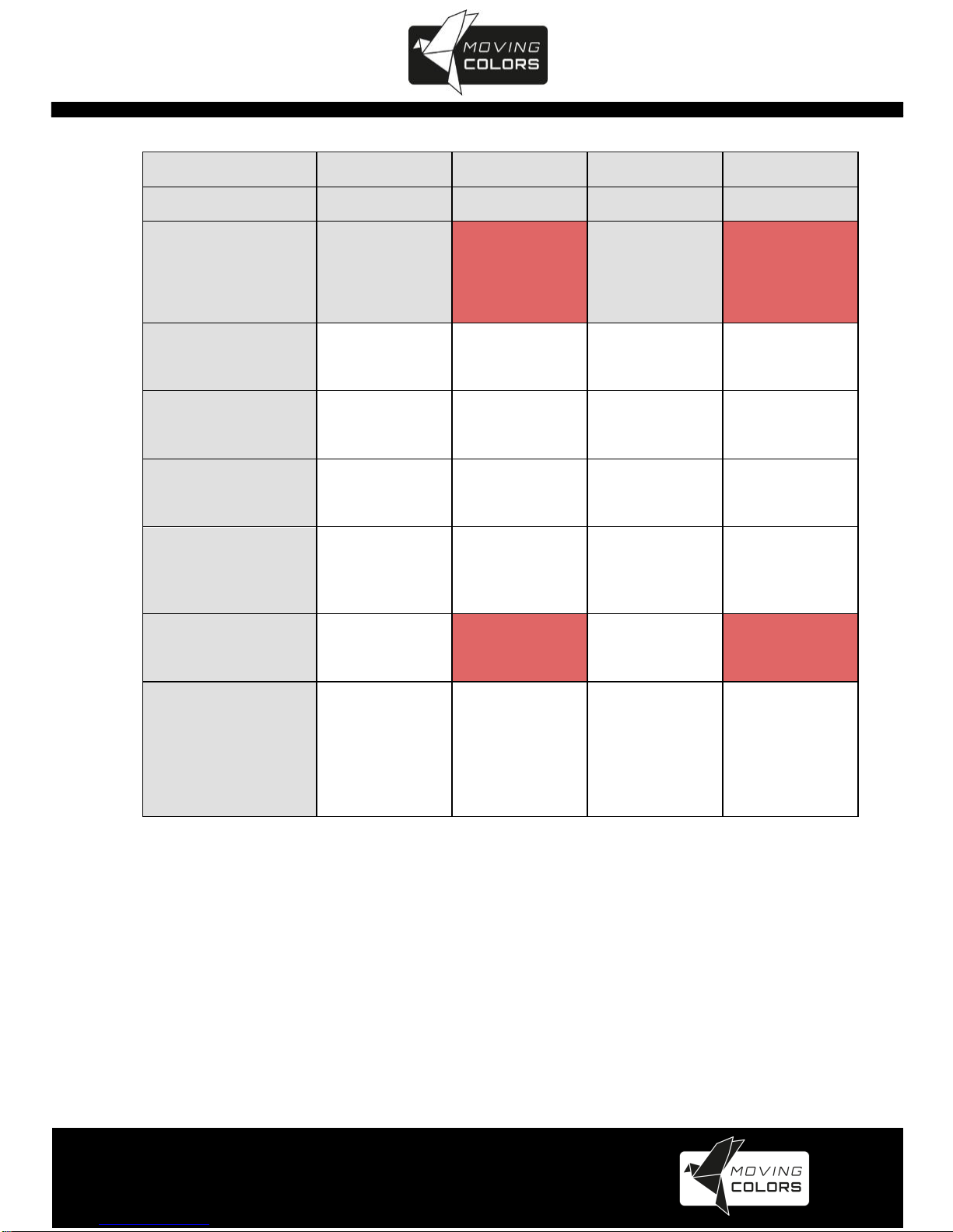
Button State for Unicast Mode: HDMI Extender:
Unicast Digital
Button State
Transmitter
Receiver
Button One :
Button Two :
Button One :
Button Two :
Short Press
Remote/Loopback*
Video Mode/
Graphic Mode*
Link on : Link
Link off : Unlink
Video Mode/
Graphic Mode*
Long Press(3 sec)
Snoop (on/off)*
Anti-Dither
(1/2/off)*
N/A
Anti-Dither
(1/2/off)*
Short Press when
Ethernet Link is Off
BYPASS
BYPASS
BYPASS
BYPASS
Long Press when
Ethernet Link is Off
BYPASS
Ethernet Jumbo Frame
(on/off)*
BYPASS
Ethernet Jumbo Frame
(on/off)*
Long Press on Boot
(Press until Red LED
Blinking)
Engineering Mode*
N/A
Engineering Mode*
N/A
Long Press on Boot
(Press until both Red LED
and Green LED Blinking)
Engineering Mode and
Reset to default*
N/A
Engineering Mode and
Reset to default*
N/A
Terms with an * will be described in the next table

www.movingcolors.eu
Yellow Line 4K/IP Extender
8
Feature /Button Feature
Descriptions
Remote/Loopback
When System is all setup, short press this button will change between remote / local loopback
Snoop (on/off)
When System is all setup and video is displayed at the client side. Long Press this button willforthe
local loop back port to be enabled for Snooping feature.
Video Mode/ Graphic Mode
User can select to change between Video Mode / Graphic Mode using this button. The button state
will be save to flash, and remember after rebooting.
Video Mode: FW will automatically trade-off between bandwidth and video quality to ensure smooth
video playing experience.
Graphic Mode: FW will fix the trade-off to ensure best graphic/text viewing experience.
Anti-Dither (1/2/off)
Anti-Dithering Mode is design to work withATI graphic cards that provide dithering output.
Dithering output is used to make coloring looks better than its original color depth. It uses visual
transient to create a half-tone effect. However, this presents great difficulty for Video Compression
to maintain low bandwidth even if the source display seems static.
Currently, we only see Dithering Output withATI graphic cards.
To resolve this issue, Moving Colors Yellow Line provides Anti-dithering for 1 bit, 2 bit, or off.
If the source content does not generate dithering output and this feature is turn on. It will create a
blocking effect because Video Engine are unable to detect pixel changes. User can avoid this
issue by turning this feature to off.
Engineering Mode
1. Static IP: 192.168.0.88
2. User can connect to http://192.168.0.88 webpage for firmware update.
3. Firmware update file name will be:
Host: webfwh.bin
Client: webfwc.bin
Reset to Default
1. Reset Any changes in SPI flash setup flag.
2. Re-generate Random mac to avoid any possible MAC collision.After Reset to Default and
reboot cycle, a new random mac will be generated.
Ethernet Jumbo Frame
1. This feature is available.
2. Enable/Disable Ethernet jumbo frame.
3. If link LED is solid then jumbo is enabled. If link LED is blinking then jumbo is disabled.
www.movingcolors.eu
Yellow Line 4K/IP Extender
9
Button State for Multicast Mode: HDMI Extender:
Multicast Digital
Button State
Transmitter
Receiver
Button One:
Button Two:
Button One:
Button Two:
Short Press
Remote/Loopback*
Video Mode/
Graphic Mode*
Link on: Link
Link off: Unlink
Video Mode/
Graphic Mode*
Long Press (3 sec)
Snoop (on/off)*
Anti-Dither
(1/2/off)
USB Link (on/off)
Anti-Dither
(1/2/off)*
Short Press when
Ethernet Link is Off
BYPASS
BYPASS
BYPASS
BYPASS
Long Press when
Ethernet Link is Off
BYPASS
Ethernet Jumbo Frame
(on/off)*
BYPASS
Ethernet Jumbo Frame
(on/off)*
Long Press on Boot
(Press until Red LED Blinking)
Engineering Mode*
Use Loopback EDID
(>A1.2)*
Engineering Mode*
Update EDID*
Long Press on Boot
(Press until
Red LED and
Green LED Blinking)
Engineering Mode and
Reset to default*
N/A
Engineering Mode
and
Reset to default*
N/A
Terms with an * will be described in the next table

www.movingcolors.eu
Yellow Line 4K/IP Extender
10
Feature /Button Feature
Descriptions
Remote/Loopback
When System is all setup, short press this button will change between remote / local loopback
Snoop (on/off)
When System is all setup and video is displayed at the client side. Long Press this button will for the
local loop back port to be enabled for Snooping feature.
Video Mode/ Graphic Mode
User can select to change between Video Mode / Graphic Mode using this button. The button state will
be save to flash, and remember after rebooting.
Video Mode: FW will automatically trade-off between bandwidth and video quality to ensure smooth
video playing experience.
Graphic Mode: FW will fix the trade-off to ensure best graphic/text viewing experience.
Anti-Dither (1/2/off)
Anti-Dithering Mode is design to work withATI graphic cards that provide dithering output. Dithering
output is used to make coloring looks better than its original color depth. It uses visual transient to
create a half-tone effect. However, this presents great difficulty for Video Compression to maintain low
bandwidth even if the source display seems static.
Currently, we only see Dithering Output withATI graphic cards.
To resolve this issue, Moving Colors Yellow Line provides Anti-dithering for 1 bit, 2 bit, or off.
If the source content does not generate dithering output and this feature is turn on. It will create a
blocking effect because Video Engine are unable to detect pixel changes. User can avoid this issue by
turning this feature to off.
Use Loopback EDID(>A1.2)
This feature should be consider with the client side "Update EDID" feature.
Update EDID
"Use Loopback EDID" & "Update EDID" feature is used for Multicast Mode to select which monitor/TV
EDID is used for system wide EDID usage.
During multicast setup, there may be monitor/TV that has lower resolution. For example, 1 monitor/TV
with 720p resolution with mostly 1080p solutions. Please select the monitor/TV with lowest resolution,
to ensure all can be displayed correctly.
For customer that are using 1 pair of Host/Client with Multicast mode, the end user must update EDID
correctly. If not, it will cause many compatibility issue.
Operation:
Once the button event is triggered correctly at the client side, when system is setup correctly for
Multicast. The selected EDID will be update to Host Side EEPROM (HU7).
The same operation applies for Loopback EDID.
In the system setup, the last EDID updated will stay in the EEPROM. If customer setup this button
even many times, the last one triggered will be applied.
USB Link (ON/OFF)
This feature is used for USB with Multicast Mode setup.
The selected client can gain control by pressing USB Link, and release control by pressing USB Link
again.
Other clients can also gain control by pressing USB Link. The control will be transfer to whichever
client requests USB Link.
Engineering Mode
1. Static IP: 192.168.0.88
2. User can connect to http://192.168.0.88 webpage for firmware update.
3. Firmware update file name will be:
Host : webfwh.bin
Client : webfwc.bin
Reset to Default
1. Reset Any changes in SPI flash setup flag.
2. Re-generate Random mac to avoid any possible MAC collision.After Reset to Default and reboot
cycle, a new random mac will be generated.
Ethernet Jumbo Frame
1. This feature is available.
2. Enable/Disable Ethernet jumbo frame.
3. If link LED is solid then jumbo is enabled. If link LED is blinking then jumbo is disabled.
www.movingcolors.eu
Yellow Line 4K/IP Extender
11
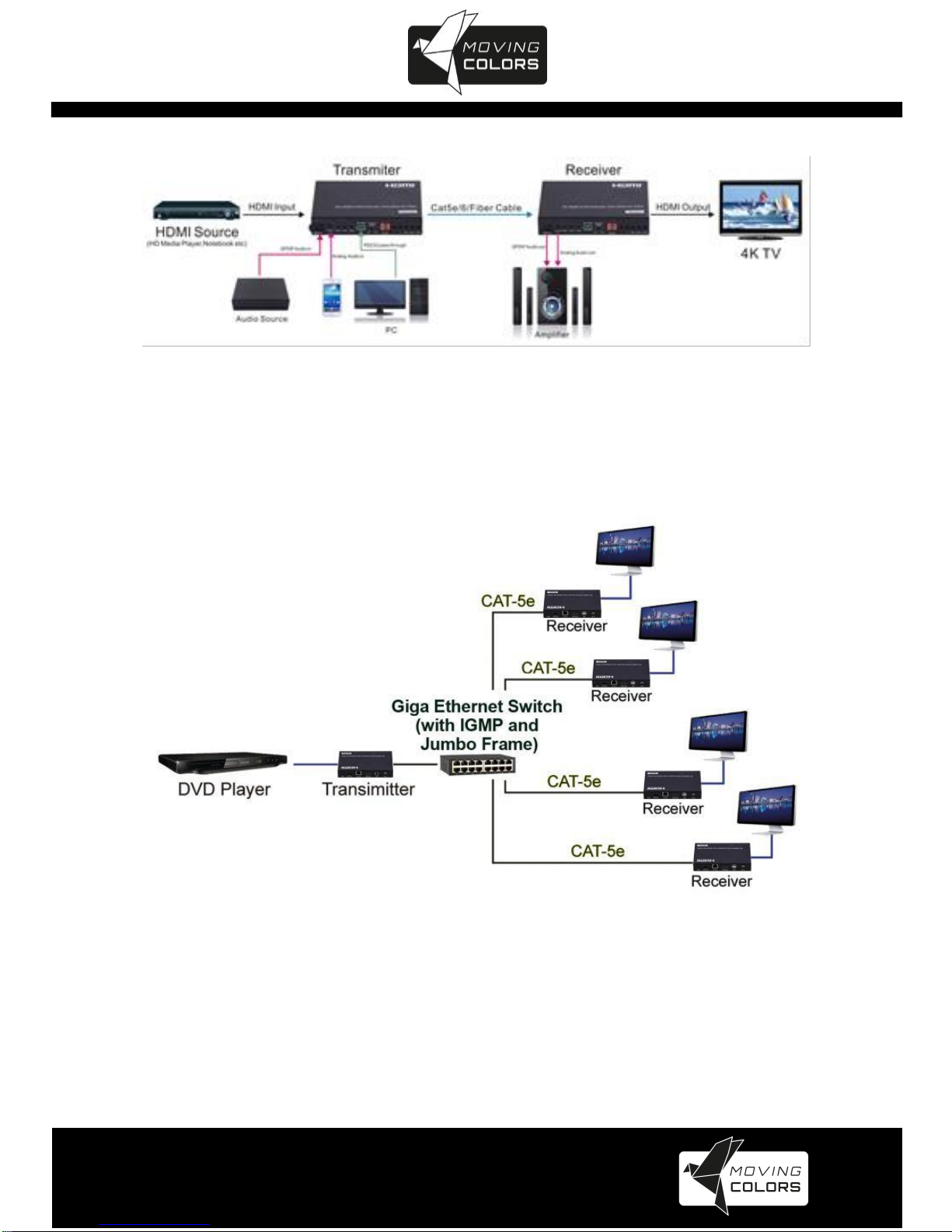
6. INSTALLATION
Device Connection
•Check the power supply is unplugged.
•Set up the group of the transmitter with the correspondent receiver
for signal extension and display.
•Connect the Transmitter to video source with HDMI cable, and
connect Receiver to a monitor or display with HDMI cable.
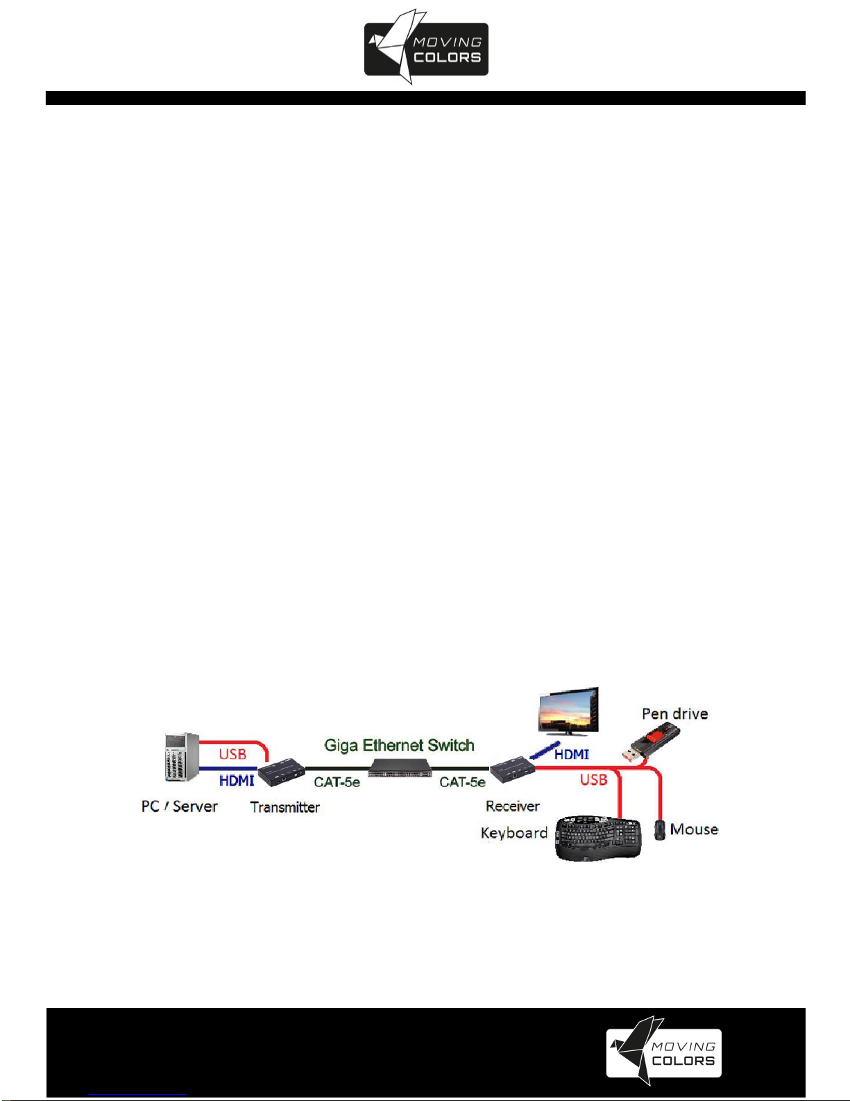
•Connect the USB cables from Transmitter to PC, and connect the
USB additional devices such as USB mouse, USB keyboard and
USB pen drive to Receiver.
•Connect Transmitter and Receiver to the Ethernet switch with
network cable.
•Power on the Transmitter, Receiver and all the connected devices.
•Power on and activate all the connected devices.
•Connect the IR extension cable with Transmitter and the IR receiver
cable with Receiver for remote control.
Typical application:
Figure 1
www.movingcolors.eu
Yellow Line 4K/IP Extender
12
Unicast configuration:
Multicast Video Distribution:
Figure 2

www.movingcolors.eu
Yellow Line 4K/IP Extender
13
Multicast Matrix Distribution:
Figure 3
Billboard & Kiosk, PC to HDMI and USB Interactive Monitor:
Figure 4

www.movingcolors.eu
Yellow Line 4K/IP Extender
14
Video wall:
Figure 5
www.movingcolors.eu
Yellow Line 4K/IP Extender
15
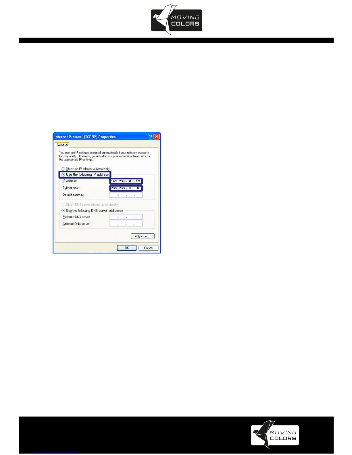
7. IP CONFIGURATION
The 4K HDMI & USB Over IP Extender can configure via LAN in the same
subnet.
1. Assign a LAN IP address to the computer in the same subnet. The IP
address default of the Transmitter and Receiver is B class Networking:
169.254.xxx.xxx.
Figure 6 Internet Protocol (TCP/IP) Properties
2. Connect the TX and RX with the Ethernet switch, Then connect the PC with
the Ethernet switch.
Because this unit support DHCP, Different unit with different IP address of the
factory reset, so The first thing we need know the IP address of each unit.
There is two way to get the IP address
1) Via “Node List”
Open the “Node List “in the “Tool” file, Press twice the “Node_list.bat” to enter
the dialog box. Then we can see all the IP address of both the TX and RX
show as bellow black dialog box.

www.movingcolors.eu
Yellow Line 4K/IP Extender
16
Figure 7
Remark: If the IP address with “Client”, It’s the IP address of the RX
If the IP address with “Gateway”, It’s the IP address the TX.
2) The second way.
Connect all devices with proper cables, please refer to Figure 9
Figure 8
www.movingcolors.eu
Yellow Line 4K/IP Extender
17
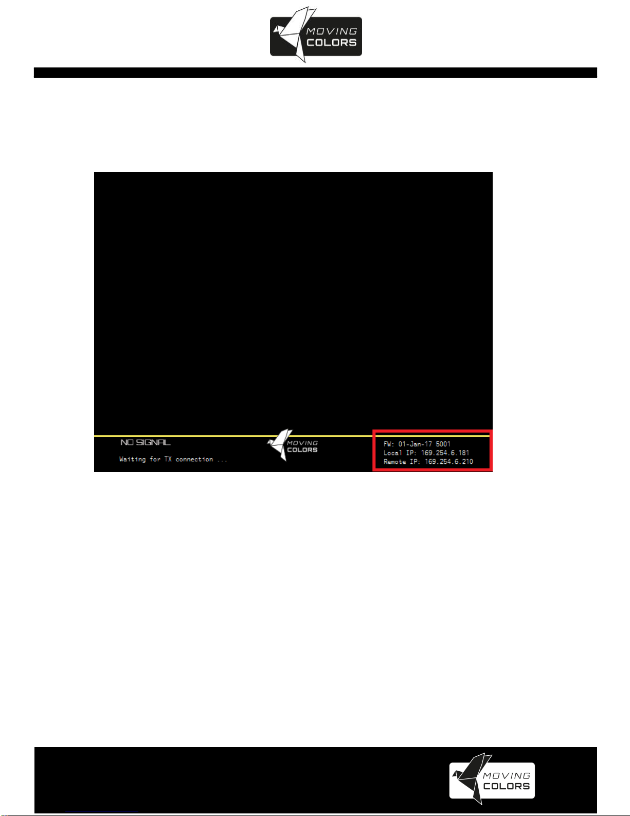
3) After activation, the device information including the Transmitter and
Receiver IP address will be shown in the lower right corner. Remember the
Transmitter and Receiver IP address on monitor screen and then plug HDMI
video source cable into Transmitter.
Figure 9
3. The administrator can input Transmitter or Receiver IP address
into address bar of web browser (Recommend the Google Chrome) to enter
the Extender Web UI.
If link success, administrator will see the Web UI as shown in Figure 11.
www.movingcolors.eu
Yellow Line 4K/IP Extender
18
Figure 10

www.movingcolors.eu
Yellow Line 4K/IP Extender
19
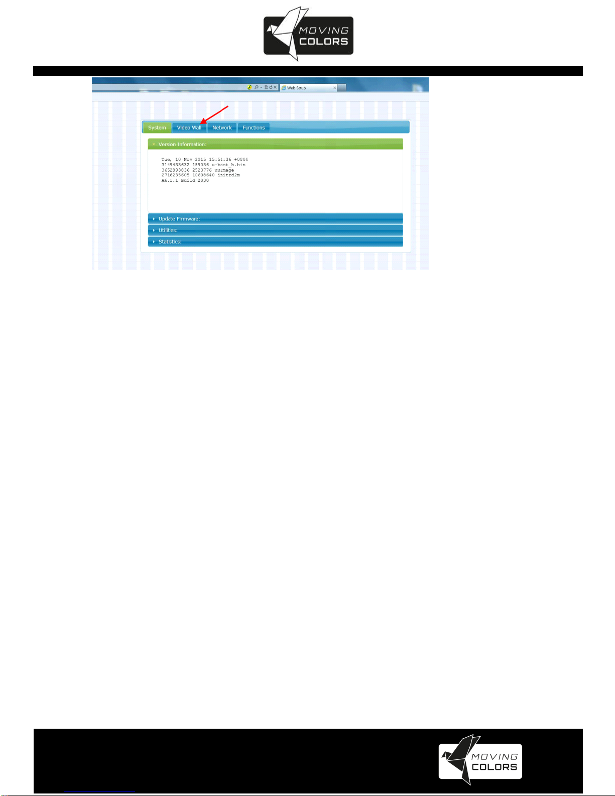
8. WEB USER INTERFACE CONFIGURATION
The relevant information of the connected extender and setting
8.1.1 [Version Information]
Indicating the firmware version and relevant information of the devices
Figure 11
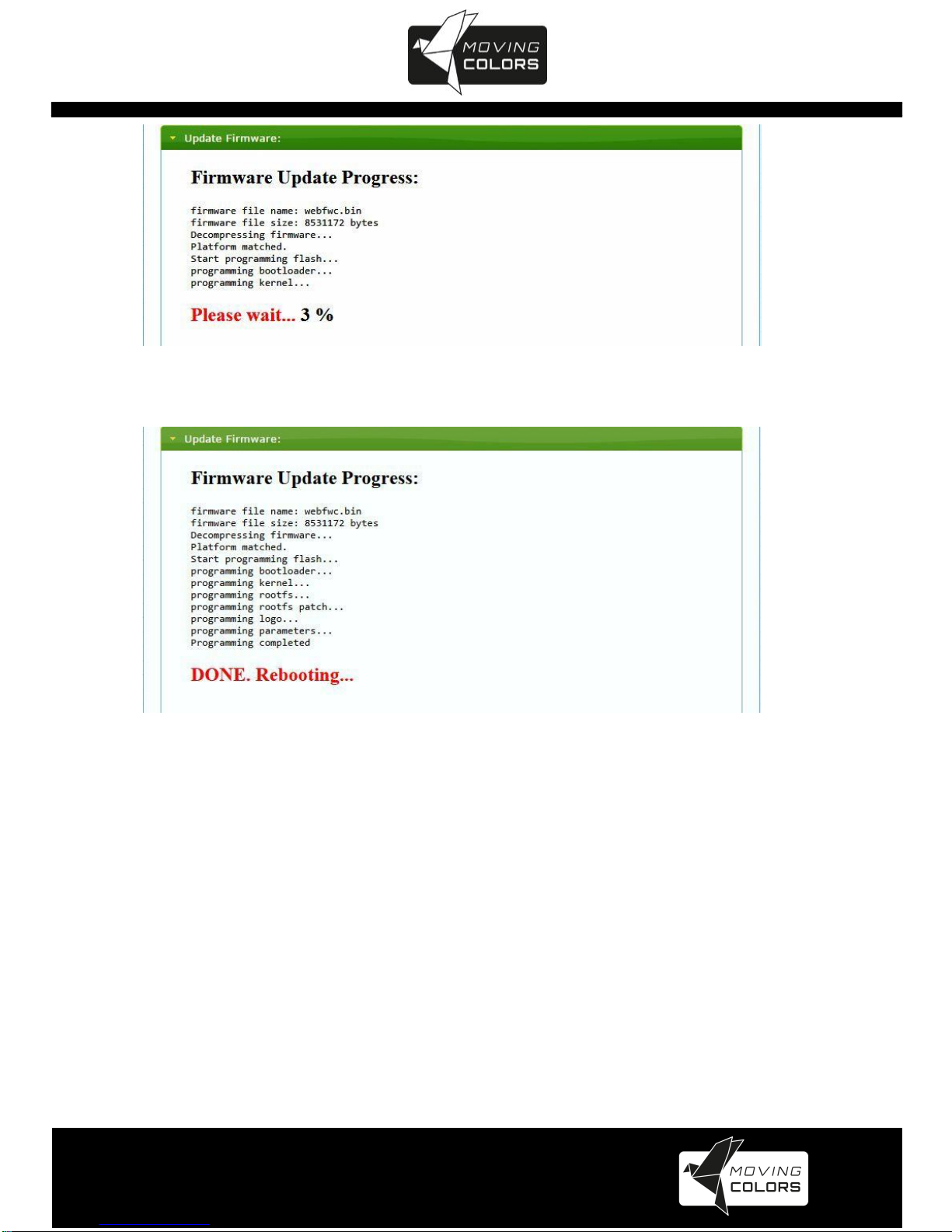
8.1.2 [Update Firmware]
To update the firmware of the connected extender, please click on the [Select
File] to select the firmware and click on [Upload] to upload the firmware and
update accordingly.
Transmitter Firmware Update: please select [webfwh.bin] to update
Receiver Firmware Update: please select [webfwc.bin] to update
It takes time to update the firmware. During the process of update, the Web
user interface shows the status as below diagram. The extender system
will reboot automatically after updating firmware. If it doesn’t reboot
automatically, please reboot to apply the new firmware manually.
www.movingcolors.eu
Yellow Line 4K/IP Extender
20
Figure 12
Figure 13
8.1.3 [Utilities]
There are some functions
Factory Default: Click on to return to the factory default when
necessary
Reboot: Click on to reboot the extender system
Console API Command: Input Linux command for advanced setting
Table of contents


